EP0599211B1 - Elektrodenverbindungsstelle zum Selbstzentrieren - Google Patents
Elektrodenverbindungsstelle zum Selbstzentrieren Download PDFInfo
- Publication number
- EP0599211B1 EP0599211B1 EP93118639A EP93118639A EP0599211B1 EP 0599211 B1 EP0599211 B1 EP 0599211B1 EP 93118639 A EP93118639 A EP 93118639A EP 93118639 A EP93118639 A EP 93118639A EP 0599211 B1 EP0599211 B1 EP 0599211B1
- Authority
- EP
- European Patent Office
- Prior art keywords
- threaded
- ridge
- nipple
- threads
- electrode
- Prior art date
- Legal status (The legal status is an assumption and is not a legal conclusion. Google has not performed a legal analysis and makes no representation as to the accuracy of the status listed.)
- Expired - Lifetime
Links
- 210000002445 nipple Anatomy 0.000 claims description 36
- OKTJSMMVPCPJKN-UHFFFAOYSA-N Carbon Chemical compound [C] OKTJSMMVPCPJKN-UHFFFAOYSA-N 0.000 claims description 15
- 229910052799 carbon Inorganic materials 0.000 claims description 11
- 238000004519 manufacturing process Methods 0.000 claims description 2
- 229910002804 graphite Inorganic materials 0.000 description 4
- 239000010439 graphite Substances 0.000 description 4
- 238000005299 abrasion Methods 0.000 description 3
- 230000000694 effects Effects 0.000 description 2
- 238000003754 machining Methods 0.000 description 2
- 239000002245 particle Substances 0.000 description 2
- 238000010420 art technique Methods 0.000 description 1
- 230000008878 coupling Effects 0.000 description 1
- 238000010168 coupling process Methods 0.000 description 1
- 238000005859 coupling reaction Methods 0.000 description 1
- 230000001066 destructive effect Effects 0.000 description 1
- 238000009826 distribution Methods 0.000 description 1
- 238000010891 electric arc Methods 0.000 description 1
- 238000010438 heat treatment Methods 0.000 description 1
- 238000010348 incorporation Methods 0.000 description 1
- VNWKTOKETHGBQD-UHFFFAOYSA-N methane Chemical compound C VNWKTOKETHGBQD-UHFFFAOYSA-N 0.000 description 1
Images





Classifications
-
- H—ELECTRICITY
- H05—ELECTRIC TECHNIQUES NOT OTHERWISE PROVIDED FOR
- H05B—ELECTRIC HEATING; ELECTRIC LIGHT SOURCES NOT OTHERWISE PROVIDED FOR; CIRCUIT ARRANGEMENTS FOR ELECTRIC LIGHT SOURCES, IN GENERAL
- H05B7/00—Heating by electric discharge
- H05B7/02—Details
- H05B7/14—Arrangements or methods for connecting successive electrode sections
-
- Y—GENERAL TAGGING OF NEW TECHNOLOGICAL DEVELOPMENTS; GENERAL TAGGING OF CROSS-SECTIONAL TECHNOLOGIES SPANNING OVER SEVERAL SECTIONS OF THE IPC; TECHNICAL SUBJECTS COVERED BY FORMER USPC CROSS-REFERENCE ART COLLECTIONS [XRACs] AND DIGESTS
- Y02—TECHNOLOGIES OR APPLICATIONS FOR MITIGATION OR ADAPTATION AGAINST CLIMATE CHANGE
- Y02P—CLIMATE CHANGE MITIGATION TECHNOLOGIES IN THE PRODUCTION OR PROCESSING OF GOODS
- Y02P10/00—Technologies related to metal processing
- Y02P10/25—Process efficiency
-
- Y—GENERAL TAGGING OF NEW TECHNOLOGICAL DEVELOPMENTS; GENERAL TAGGING OF CROSS-SECTIONAL TECHNOLOGIES SPANNING OVER SEVERAL SECTIONS OF THE IPC; TECHNICAL SUBJECTS COVERED BY FORMER USPC CROSS-REFERENCE ART COLLECTIONS [XRACs] AND DIGESTS
- Y10—TECHNICAL SUBJECTS COVERED BY FORMER USPC
- Y10S—TECHNICAL SUBJECTS COVERED BY FORMER USPC CROSS-REFERENCE ART COLLECTIONS [XRACs] AND DIGESTS
- Y10S403/00—Joints and connections
- Y10S403/05—Carbon electrode
-
- Y—GENERAL TAGGING OF NEW TECHNOLOGICAL DEVELOPMENTS; GENERAL TAGGING OF CROSS-SECTIONAL TECHNOLOGIES SPANNING OVER SEVERAL SECTIONS OF THE IPC; TECHNICAL SUBJECTS COVERED BY FORMER USPC CROSS-REFERENCE ART COLLECTIONS [XRACs] AND DIGESTS
- Y10—TECHNICAL SUBJECTS COVERED BY FORMER USPC
- Y10T—TECHNICAL SUBJECTS COVERED BY FORMER US CLASSIFICATION
- Y10T403/00—Joints and connections
- Y10T403/55—Member ends joined by inserted section
- Y10T403/556—Section threaded to member
Definitions
- This invention relates to a threaded nipple for connecting together sections of carbon (including graphite) electrodes to provide a longitudinally extending electrode column for use in an electric arc furnace or the like. More particularly, the present invention is directed to a threaded nipple for connecting axially aligned electrode sections and establishing and maintaining coaxial alignment therebetween.
- U.S. Patent 4,152,533 is directed to nipple joint breakage and addresses the problem of stresses at the first few bottom threads of an electrode socket, by chamfering these threads.
- U.S. Patent 4,375,340 addresses the problem of stresses at or near the mid-length of a threaded nipple which are relieved to increase the strength of the joint.
- US-A-2 970 854 discloses an electrode joint comprising two threaded electrode sections and a threaded nipple.
- a shrinkable shim is incorporated between the flanks of the threads of the nipple and of the threads of at least one of the electrode sections for providing substantially even distribution of clearance between the nipple and the electrode sections. During thermal heating the shim will fuse or shrink to reduce its thickness thus allowing more room for the threads to expand and thus also providing a possible break of the electrode sections or of the nipple.
- Figure 1 shows a conventional electrode joint arrangement for coupling the electrode sections 10 and 20, which is shown also in Figure 1(A).
- the electrode sections 10, 20 are desirably coaxially aligned to avoid mechanical stress with their longitudinal axes 30, 40 coincident as shown in Figure 1 and Figure 1(A), and also coincident with the central longitudinal axis 60 of cylinder-shaped threaded nipple 70 as shown.
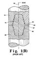
- An alternate conventional joint arrangement is shown in Figure 1(B) wherein the threaded nipple 70 is double tapered.
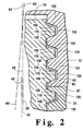
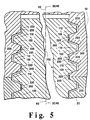
- a threaded nipple in accordance with the present invention for maintaining coaxial alignment and avoiding joint breakage and failure is shown at 700 in Figure 3, and in section in Figure 4, in which the threaded nipple 700 is provided with spaced apart integral threads 210 on root 215 which, when in use, threadably engage grooves 220, 222 of electrode sections 10, 20 as shown in Figure 5.
- a ridge 250 is provided integral with root 215 and located adjacently intermediate threads 210 to extend outwardly from root 215, but to a substantially less extent than threads 210.
- the threaded nipple in accordance with the present invention can have the double-taper shape of Figure 1(B).
- the outward extension 270 of ridge 250 is suitably from 5 to 20% of the outward extension 275 of thread 210, also illustrated in Figure 4.
- Ridge 250 is preferably provided with a substantially pointed edge 255 so that upon engagement of threaded nipple 700 in a correspondingly threaded electrode section 10, 20, the recessed ridge 250 abradably bears against the flat surfaced crests 300, 302 in the sockets of electrode sections 10, 20, which separate the grooves 220, 222.
- Ridge 250 is preferably angular and pointed as shown at 255 in Figure 3 to facilitate abrasion to a flat supporting surface after abrasion.
- the ridge 250 is preferably positioned slightly closer to the adjacent load bearing flank 100 of threaded nipple 700, so that, with reference to Figure 7, the distance A is about 5 to 20% longer than distance B.
- Figure 7 shows, in section a threading tool having a notch N for creating a ridge 250 in the course of creating the threads 210 of Figure 3.
- Exemplary tool dimensions are shown in the legend for Figure 7.
- the ridge 250 be in the form of a continuous helix integral with the carbon (or graphite) root 215 and substantially coextensive with threads 210.
- the ridge 250 can be discontinuous, by the incorporation of a plurality of spaced apart slots, such as shown exemplarily at 330 in Figure 3. Such slots should in the aggregate, constitute less than one quarter of the total length of ridge 250.
- the slots 330 can provide a relief passage for carbon particles resulting from abrasion.
- the threaded nipple 700 shown in Figure 3, is initially engaged to an electrode section, and ridge 250, gradually and continuously bears against the flat surfaced crests of the socket of an electrode section and is gradually abraded as illustrated at 327 in Figure 6 so as to, in effect, coaxially wedge the nipple 700 in the socket as shown in Figure 5.
- Gutters 401,403 in root 215, which can be coextensive with ridge 250 may be optionally provided, as shown in Figure 4(c), to receive abraded particles.
Landscapes
- Physics & Mathematics (AREA)
- Engineering & Computer Science (AREA)
- Plasma & Fusion (AREA)
- Discharge Heating (AREA)
- Furnace Details (AREA)
- Vertical, Hearth, Or Arc Furnaces (AREA)
- Golf Clubs (AREA)
Claims (6)
- Ein angefertigtes Teil, ein Kohlenstoffnippel mit Gewinde (700) zur Verbindung eines Paares gegenüberliegender Kohlenstoffelektroden-Teilstücke (10, 20), jedes mit entsprechender gegenüberliegender Buchse mit Gewinde, wobei jede Buchse mit Gewinde Gewinderillen (220, 222) aufweist, getrennt durch im wesentlichen ebenflächige Kämme (300, 302), der besagte Kohlenstoffnippel mit Gewinde (700) umfaßt:(i) ein sich der Länge nach erstreckendes Grundteilstück (215);(ii) auseinanderliegende Gewindegänge (210) auf dem Grundteilstück (215), die sich davon nach außen erstrecken und integraler Bestandteil hiervon sind, für das gewindemäßige Eingreifen der Gewinderillen (220, 222) eines Elektrodenteilstücks (10, 20);gekennzeichnet durch
(iii) einen abnutzbaren Steg (250) des Grundteilstücks (215), das Teil des Ganzen ist, unmittelbar angrenzend an die auseinanderliegenden Gewindegänge (210) auf dem Grundteilstück (215) und sich von diesem Grundteilstück aus (215) erstreckend, jedoch in einem wesentlich geringeren Ausmaß als die auseinanderliegenden Gewindegänge (210), so daß bei Gewindeeingriff des mit Gewinde versehenen Kohlenstoffnippels (700) mit einem Elektrodenteilstück (10, 20) der Steg (250) durch Abnutzung abgetragen wird und eine ebene Fläche (320) hinterläßt, die gegen die ebenflächigen Kämme (300, 302) der mit Gewinde versehenen Buchse drückt, welche die Gewinderillen (220, 222) der Elektrodenbuchse trennen. - Ein angefertigtes Teil nach Anspruch 1, wobei der Steg (250) im wesentlichen kontinuierlich und koextensiv mit den Gewinden (210) und dem Grundteilstück (215) ist.
- Ein angefertigtes Teil nach Anspruch 1 oder 2, wobei der Steg (250) von den angrenzenden Gewinden (210) auf dem Grundteilstück (215) abgesetzt ist.
- Ein angefertigtes Teil nach Anspruch 3, wobei der Steg (250) geringfügig näher zu einem angrenzenden Gewinde (210) liegt, so daß er unter Abnutzung gegen das zentrale Teilstück des ebenflächigen Kamms (300, 302) der Buchse eines Elektrodenteilstücks (10, 20) drückt.
- Ein angefertigtes Teil nach einem der Ansprüche 1 bis 4, wobei eine Vielzahl von Vertiefungen (330) im Steg (250) vorhanden ist.
- Eine Kohlenstoffelektrodenverbindung bestehend aus einem Paar gegenüberliegender anstoßender Elektrodenteilstücke (10, 20), wobei jedes Teilstück jeweils eine gegenüberliegende mit Gewinde versehene Buchse aufweist, wobei jede Buchse mit Gewinderillen (220, 222) versehen ist, getrennt durch im wesentlichen ebenflächige Kämme (300), 302) und einen mit Gewinde versehenen Kohlenstoffnippel (700) nach einem der Ansprüche 1 bis 5.
Applications Claiming Priority (2)
| Application Number | Priority Date | Filing Date | Title |
|---|---|---|---|
| US981606 | 1992-11-25 | ||
| US07/981,606 US5336015A (en) | 1992-11-25 | 1992-11-25 | Self centering electrode joint |
Publications (2)
| Publication Number | Publication Date |
|---|---|
| EP0599211A1 EP0599211A1 (de) | 1994-06-01 |
| EP0599211B1 true EP0599211B1 (de) | 1997-10-22 |
Family
ID=25528508
Family Applications (1)
| Application Number | Title | Priority Date | Filing Date |
|---|---|---|---|
| EP93118639A Expired - Lifetime EP0599211B1 (de) | 1992-11-25 | 1993-11-19 | Elektrodenverbindungsstelle zum Selbstzentrieren |
Country Status (13)
| Country | Link |
|---|---|
| US (1) | US5336015A (de) |
| EP (1) | EP0599211B1 (de) |
| CN (1) | CN1050964C (de) |
| AU (1) | AU663839B2 (de) |
| BR (1) | BR9304811A (de) |
| CA (1) | CA2109909C (de) |
| DE (1) | DE69314749T2 (de) |
| ES (1) | ES2108190T3 (de) |
| NO (1) | NO306440B1 (de) |
| PL (1) | PL172238B1 (de) |
| RU (1) | RU2129341C1 (de) |
| UA (1) | UA27762C2 (de) |
| ZA (1) | ZA938797B (de) |
Families Citing this family (13)
| Publication number | Priority date | Publication date | Assignee | Title |
|---|---|---|---|---|
| DE4400001A1 (de) * | 1994-01-02 | 1995-07-06 | Gerd Hoermansdoerfer | Verfahren zur Herstellung eines Gewindes mit veränderlich modifzierbarem Gewindeprofil und bevorzugte Anwendung des Verfahrens |
| US5575582A (en) * | 1995-01-18 | 1996-11-19 | Ucar Carbon Technology Corporation | Fastening device for securing electrode joints |
| US6500022B2 (en) * | 2001-03-30 | 2002-12-31 | Ucar Carbon Company Inc. | Threaded pin for carbon electrodes |
| NL1020069C1 (nl) * | 2002-02-27 | 2002-07-22 | Barfix Bermuda Ltd | Werkwijze en inrichting voor het verbinden van betonstaal. |
| GB2386405A (en) * | 2002-03-15 | 2003-09-17 | Charles Bickford | Threaded fixing device and method |
| DE10302956B3 (de) * | 2003-01-24 | 2004-07-22 | Sgl Carbon Ag | Kohlenstoffelektroden und deren Verbindungselemente mit gerichtet strukturierten Kontaktflächen |
| US6952438B2 (en) * | 2003-10-31 | 2005-10-04 | Sgl Carbon Ag | Threaded connection for carbon and/or graphite electrode columns |
| US20050175062A1 (en) * | 2004-01-20 | 2005-08-11 | Brian Bowman | End-face seal for graphite electrodes |
| US7081597B2 (en) * | 2004-09-03 | 2006-07-25 | The Esab Group, Inc. | Electrode and electrode holder with threaded connection |
| SG179322A1 (en) | 2010-10-01 | 2012-04-27 | Infastech Ip Pte Ltd | Threaded fastener |
| US10066656B2 (en) * | 2011-11-22 | 2018-09-04 | Lock-N-Stitch, Inc. | Threaded fastener having a thread crest greater than its thread root and “V” angles on the crest and root |
| DE102016010341B4 (de) * | 2015-08-28 | 2024-08-01 | Lincoln Global, Inc. | Plasmabrenner und komponenten des plasmabrenners |
| US10265110B2 (en) * | 2015-10-19 | 2019-04-23 | Alphatec Spine, Inc. | Pedicle screw with raised root |
Family Cites Families (16)
| Publication number | Priority date | Publication date | Assignee | Title |
|---|---|---|---|---|
| US1049624A (en) * | 1912-03-21 | 1913-01-07 | Siemens & Co Geb | Means for joining electrodes. |
| US2970854A (en) * | 1958-08-06 | 1961-02-07 | Union Carbide Corp | Electrode joint |
| US3134616A (en) * | 1958-11-07 | 1964-05-26 | Siemens Planiawerke Ag | Double-conical nipple joint for carbon electrodes |
| US3207023A (en) * | 1961-12-01 | 1965-09-21 | Illinois Tool Works | Screw fastener |
| US3176746A (en) * | 1963-04-01 | 1965-04-06 | Walton Marvin | Self-holding screw member |
| CA1095106A (en) * | 1977-04-12 | 1981-02-03 | Erco Industries Limited | Electrode joints |
| US4159184A (en) * | 1977-06-07 | 1979-06-26 | Union Carbide Corporation | Friable thread electrode joint |
| US4152533A (en) * | 1978-04-27 | 1979-05-01 | Great Lakes Carbon Corporation | Electrode joint |
| US4375340A (en) * | 1980-03-21 | 1983-03-01 | Great Lakes Carbon Corporation | Carbon electrode joint |
| FR2514086A1 (fr) * | 1981-10-05 | 1983-04-08 | Itw De France | Dispositif d'assemblage, en particulier du type insert, pour le maintien d'un element quelconque sur des supports en matiere plastique, speciaux, rigides et sujets a deterioration a la fixation |
| US4439077A (en) * | 1982-02-11 | 1984-03-27 | Godsted Kent B | Concrete screw anchor |
| US4576534A (en) * | 1983-08-04 | 1986-03-18 | Illinois Tool Works Inc. | Thread form for soft material |
| US4679206A (en) * | 1985-05-15 | 1987-07-07 | Union Carbide Corporation | Electrode joint thread form |
| SU1725407A1 (ru) * | 1988-01-18 | 1992-04-07 | Предприятие П/Я Ю-9877 | Узел резьбового соединени графитированных электродов |
| SU1750068A1 (ru) * | 1990-07-17 | 1992-07-23 | Запорожский индустриальный институт | Способ определени качества ниппельного соединени секций графитированного электрода |
| US5190426A (en) * | 1992-03-02 | 1993-03-02 | Illinois Tool Works Inc. | Concrete fastener |
-
1992
- 1992-11-25 US US07/981,606 patent/US5336015A/en not_active Expired - Lifetime
-
1993
- 1993-11-19 DE DE69314749T patent/DE69314749T2/de not_active Expired - Fee Related
- 1993-11-19 ES ES93118639T patent/ES2108190T3/es not_active Expired - Lifetime
- 1993-11-19 EP EP93118639A patent/EP0599211B1/de not_active Expired - Lifetime
- 1993-11-24 CN CN93120594A patent/CN1050964C/zh not_active Expired - Fee Related
- 1993-11-24 NO NO934255A patent/NO306440B1/no unknown
- 1993-11-24 ZA ZA938797A patent/ZA938797B/xx unknown
- 1993-11-24 BR BR9304811A patent/BR9304811A/pt not_active IP Right Cessation
- 1993-11-24 RU RU93052366A patent/RU2129341C1/ru not_active IP Right Cessation
- 1993-11-24 CA CA002109909A patent/CA2109909C/en not_active Expired - Fee Related
- 1993-11-24 PL PL93301186A patent/PL172238B1/pl not_active IP Right Cessation
- 1993-11-24 AU AU51932/93A patent/AU663839B2/en not_active Ceased
- 1993-11-25 UA UA93003756A patent/UA27762C2/uk unknown
Also Published As
| Publication number | Publication date |
|---|---|
| DE69314749D1 (de) | 1997-11-27 |
| US5336015A (en) | 1994-08-09 |
| RU2129341C1 (ru) | 1999-04-20 |
| NO934255D0 (no) | 1993-11-24 |
| AU5193293A (en) | 1994-06-09 |
| PL172238B1 (pl) | 1997-08-29 |
| AU663839B2 (en) | 1995-10-19 |
| NO934255L (no) | 1994-05-26 |
| CN1093214A (zh) | 1994-10-05 |
| BR9304811A (pt) | 1994-07-05 |
| PL301186A1 (en) | 1994-05-30 |
| ZA938797B (en) | 1994-06-30 |
| CN1050964C (zh) | 2000-03-29 |
| EP0599211A1 (de) | 1994-06-01 |
| CA2109909C (en) | 1996-07-30 |
| DE69314749T2 (de) | 1998-03-26 |
| CA2109909A1 (en) | 1994-05-26 |
| NO306440B1 (no) | 1999-11-01 |
| UA27762C2 (uk) | 2000-10-16 |
| ES2108190T3 (es) | 1997-12-16 |
Similar Documents
| Publication | Publication Date | Title |
|---|---|---|
| US5336015A (en) | Self centering electrode joint | |
| US4152533A (en) | Electrode joint | |
| US4384737A (en) | Threaded joint for well casing and tubing | |
| US3388935A (en) | Threaded drill rod element | |
| CN102395747A (zh) | 用于钻探和操作油气井的管状部件以及生成的螺纹连接部 | |
| US20020141476A1 (en) | Electrode joint | |
| CA1252820A (en) | Connection between sections of a carbon or graphite electrode | |
| JP3105440B2 (ja) | 電極継手の緩みを防止するための固着装置 | |
| US3822952A (en) | Drill rod coupling | |
| CA1297145C (en) | Electrode joint thread form | |
| KR102754081B1 (ko) | 길이방향 그루브가 있는 변형 가능한 슬리브를 사용하는 볼트 체결된 조인트 | |
| KR102179856B1 (ko) | 폴리에틸렌 수도용 파이프 이음장치 | |
| JP3760098B2 (ja) | ドリル接続具 | |
| US4375340A (en) | Carbon electrode joint | |
| EP0101819B1 (de) | Konisches Elektrodengewinde und Verfahren zum Verbinden von zwei Elektrodenabschnitten | |
| CA1095106A (en) | Electrode joints | |
| US20060291525A1 (en) | Electrode joint | |
| EP0101783B1 (de) | Satz aus selbstsichernder Mutter und Gegenmutter | |
| US3771889A (en) | Nipple-electrode assembly and joint | |
| US5415755A (en) | Fastening element for securing electrode joints and the electrode using such | |
| SU1017177A3 (ru) | Штуцерное соединение дл электрода печи | |
| EP0202128B1 (de) | Elektroden und ihre Verbindungsstücke | |
| RU223480U1 (ru) | Фреза концевая | |
| EP1728412B1 (de) | Gewindestift für kohlenstoffelektroden und elektrodenbaugrupe mit einem gewindestift | |
| US4691324A (en) | Electrode connection |
Legal Events
| Date | Code | Title | Description |
|---|---|---|---|
| PUAI | Public reference made under article 153(3) epc to a published international application that has entered the european phase |
Free format text: ORIGINAL CODE: 0009012 |
|
| AK | Designated contracting states |
Kind code of ref document: A1 Designated state(s): DE ES FR IT |
|
| 17P | Request for examination filed |
Effective date: 19940621 |
|
| 17Q | First examination report despatched |
Effective date: 19960806 |
|
| GRAG | Despatch of communication of intention to grant |
Free format text: ORIGINAL CODE: EPIDOS AGRA |
|
| GRAH | Despatch of communication of intention to grant a patent |
Free format text: ORIGINAL CODE: EPIDOS IGRA |
|
| GRAH | Despatch of communication of intention to grant a patent |
Free format text: ORIGINAL CODE: EPIDOS IGRA |
|
| GRAA | (expected) grant |
Free format text: ORIGINAL CODE: 0009210 |
|
| ITF | It: translation for a ep patent filed | ||
| AK | Designated contracting states |
Kind code of ref document: B1 Designated state(s): DE ES FR IT |
|
| REF | Corresponds to: |
Ref document number: 69314749 Country of ref document: DE Date of ref document: 19971127 |
|
| ET | Fr: translation filed | ||
| REG | Reference to a national code |
Ref country code: ES Ref legal event code: FG2A Ref document number: 2108190 Country of ref document: ES Kind code of ref document: T3 |
|
| PLBE | No opposition filed within time limit |
Free format text: ORIGINAL CODE: 0009261 |
|
| STAA | Information on the status of an ep patent application or granted ep patent |
Free format text: STATUS: NO OPPOSITION FILED WITHIN TIME LIMIT |
|
| 26N | No opposition filed | ||
| PGFP | Annual fee paid to national office [announced via postgrant information from national office to epo] |
Ref country code: FR Payment date: 20061117 Year of fee payment: 14 |
|
| PGFP | Annual fee paid to national office [announced via postgrant information from national office to epo] |
Ref country code: ES Payment date: 20061124 Year of fee payment: 14 |
|
| PGFP | Annual fee paid to national office [announced via postgrant information from national office to epo] |
Ref country code: IT Payment date: 20061130 Year of fee payment: 14 |
|
| PGFP | Annual fee paid to national office [announced via postgrant information from national office to epo] |
Ref country code: DE Payment date: 20070102 Year of fee payment: 14 |
|
| PG25 | Lapsed in a contracting state [announced via postgrant information from national office to epo] |
Ref country code: DE Free format text: LAPSE BECAUSE OF NON-PAYMENT OF DUE FEES Effective date: 20080603 |
|
| REG | Reference to a national code |
Ref country code: FR Ref legal event code: ST Effective date: 20080930 |
|
| REG | Reference to a national code |
Ref country code: ES Ref legal event code: FD2A Effective date: 20071120 |
|
| PG25 | Lapsed in a contracting state [announced via postgrant information from national office to epo] |
Ref country code: FR Free format text: LAPSE BECAUSE OF NON-PAYMENT OF DUE FEES Effective date: 20071130 Ref country code: ES Free format text: LAPSE BECAUSE OF NON-PAYMENT OF DUE FEES Effective date: 20071120 |
|
| PG25 | Lapsed in a contracting state [announced via postgrant information from national office to epo] |
Ref country code: IT Free format text: LAPSE BECAUSE OF NON-PAYMENT OF DUE FEES Effective date: 20071119 |