EP0599451A1 - Unité de visualisation à angle de vision limité - Google Patents
Unité de visualisation à angle de vision limité Download PDFInfo
- Publication number
- EP0599451A1 EP0599451A1 EP93306970A EP93306970A EP0599451A1 EP 0599451 A1 EP0599451 A1 EP 0599451A1 EP 93306970 A EP93306970 A EP 93306970A EP 93306970 A EP93306970 A EP 93306970A EP 0599451 A1 EP0599451 A1 EP 0599451A1
- Authority
- EP
- European Patent Office
- Prior art keywords
- display unit
- visual display
- protective screen
- screen according
- half shell
- Prior art date
- Legal status (The legal status is an assumption and is not a legal conclusion. Google has not performed a legal analysis and makes no representation as to the accuracy of the status listed.)
- Withdrawn
Links
- 230000000007 visual effect Effects 0.000 title claims abstract description 26
- 230000001681 protective effect Effects 0.000 claims abstract description 19
- 239000000853 adhesive Substances 0.000 claims abstract description 7
- 230000001070 adhesive effect Effects 0.000 claims abstract description 7
- 239000004744 fabric Substances 0.000 claims description 2
- 229920002379 silicone rubber Polymers 0.000 description 4
- 239000004945 silicone rubber Substances 0.000 description 4
- 239000004677 Nylon Substances 0.000 description 1
- 230000015572 biosynthetic process Effects 0.000 description 1
- 230000004313 glare Effects 0.000 description 1
- 229920001778 nylon Polymers 0.000 description 1
- 239000004417 polycarbonate Substances 0.000 description 1
- 229920000515 polycarbonate Polymers 0.000 description 1
- 238000003466 welding Methods 0.000 description 1
Images
Classifications
-
- H—ELECTRICITY
- H01—ELECTRIC ELEMENTS
- H01J—ELECTRIC DISCHARGE TUBES OR DISCHARGE LAMPS
- H01J29/00—Details of cathode-ray tubes or of electron-beam tubes of the types covered by group H01J31/00
- H01J29/86—Vessels; Containers; Vacuum locks
- H01J29/89—Optical or photographic arrangements structurally combined or co-operating with the vessel
-
- H—ELECTRICITY
- H01—ELECTRIC ELEMENTS
- H01J—ELECTRIC DISCHARGE TUBES OR DISCHARGE LAMPS
- H01J2229/00—Details of cathode ray tubes or electron beam tubes
- H01J2229/89—Optical components associated with the vessel
- H01J2229/8905—Direction sensitive devices for controlled viewing angle
Definitions
- This invention relates to a protective screen for a visual display unit comprising a transparent plate, a supporting frame for the plate and fixing means for fixing the supporting frame to the body of the visual display unit.
- a screen of the type defined hereinabove is known, in which the frame can be positioned so as to position the screen adjacent to the visual display unit.
- This screen protects the user from the glare caused by external light sources. For reasons of confidentiality, it is sometimes necessary to prevent viewing by persons other than those directly in front of the visual display unit.
- Preferred embodiments of the invention provide a protective screen which allows for viewing of the surface of the visual display unit over only a relatively limited angle while preventing viewing by persons outside this angle and which at the same time can be fixed in a simple manner to the body of the visual display unit.
- the screen according to the present invention is characterised in that the plate comprises a louvre-type film known per se which defines parallel microwindows in order to define a limited viewing angle and in which the fixing means comprise a first part which can be fixed to the frame and a second part which can be separated from the first part and can be fixed to the visual display unit.
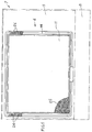
- a protective screen is designated in general by the reference numeral 6 and is applied to a portable computer 7 of known type which is shown by dash-dotted lines in the drawings and comprises a body 8, a cover 9 and a visual display unit 11 housed in the cover 9.
- the screen 6 comprises a supporting frame 12 for a transparent plate 13.
- the supporting frame 12 comprises a front half shell 14 having a seat 16 provided over the entire edge of the front half shell 14, and a rear half shell 17.
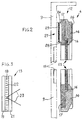
- a plate 13 has a thickness of approximately 1 mm and comprises an intermediate louvre film 18 of slats of black silicone rubber 25 which form the walls of parallel microwindows 22 of very fine layers of transparent silicone rubber.
- the film 18 is inserted between two outer plates 19 and 21 of polycarbonate.
- the combination of the black silicone rubber, the transparent silicone rubber and the thickness of the intermediate film 18 creates a row of microwindows or passages 22 so as to define a viewing angle 23 which varies considerably as a function of the variation in the thickness of the intermediate film 18.
- the thickness of the film 18 is approximately 60°.
- the outer plate 21 has its respective outer surface treated so that the coefficient of reflection is minimal.
- the plate 13 with the frame 12 is rectangular, the base being greater than the height, and has dimensions corresponding to those of the visual display unit 11.
- the direction of the slats 25 is inclined by approximately 13° with respect to a direction perpendicular to that of the base, although the inclination can vary from 1° to 30°.
- the plate 13 is positioned in the seat 16 and is locked to the rear half shell 17 which is positioned against the front half shell 14 and the two half shells 14 and 17 are thus rigidly welded together by means of ultrasonic welding so as to form one piece with the plate 13.
- the rear half shell 17 is provided on its two lateral edges with two housings 24 positioned in the vicinity of the upper edge of the half shell 17.
- the front half shell 14 is provided on its two lateral edges with two toothed projections 26.
- the fixing means 27 comprise two tables of adhesive velcro 28 each having a first element 28 which is positioned and fixed by means of adhesive in the respective housing 24 of the rear half shell 17 and a second element 29 which is positioned and fixed by means of adhesive on the inner part of the cover 9 adjacent to the visual display unit 11, so that the base of the plate 13 is parallel to the base of the said visual display unit 11.
- the protective screen 6 is mounted on a portable computer 7 in the following manner.
- the screen 6 is positioned with the two first elements 28 registering with the two second element 29 and the pressure is applied to the two toothed projections 26 on the front half shell 14 until the elements 28 and 29 are gripped to each other.
- the screen 6 is thus positioned with the plate 13 in front of the visual display unit 11.
- the screen 6 is lifted by means of the lower part of the half shell 14 until the elements 28 and 29 of the velcro 27 are freed therefrom.
- the protective screen 6 described hitherto and used in the non-limiting example on a portable computer 7 allows for confidential viewing of the visual display unit 11 by only the operator over an angle of 60°, the angle being variable between 30° and 90°. It is thus clear that the operator can operate in any area, such as office, aeroplane, train, etc. with complete confidentiality. Moreover, the protective screen 6 can be applied to any visual dislay unit of large or small dimenensions, thereby allowing for confidential viewing. The inclination of the slats 25 between 1° and 30° moreover prevents the formation of interference fringes on the visual display unit 11.
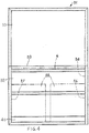
- the screen 6 can be placed in a container or case 31 (Fig. 4) of nylon fabric having a lower part 32 and an upper part 33.
- the lower part 32 comprises a central pocket 34 adapted to house the protective screen 6, shown by dash-dotted lines, and two side pockets 36 and 37 of small dimensions to house, e.g. two floppy discs 38, shown by dash-dotted lines, or any other components for use of the protable computer 7.
- the upper part 33 can be folded along the line 39 in order to engage with a strip of velcro 41 of the lower part 32 in order to keep the container 31 closed.
- the inner surface of the upper part 33 is rough and moreover has advantageously been stiffened in order to be used as a face for the use of the mouse.
Landscapes
- Devices For Indicating Variable Information By Combining Individual Elements (AREA)
- Optical Elements Other Than Lenses (AREA)
- Transforming Electric Information Into Light Information (AREA)
Applications Claiming Priority (2)
| Application Number | Priority Date | Filing Date | Title |
|---|---|---|---|
| ITTO920238U | 1992-10-01 | ||
| IT000238 IT227651Y1 (it) | 1992-10-01 | 1992-10-01 | Schermo di porotezione per visualizzatore. |
Publications (1)
| Publication Number | Publication Date |
|---|---|
| EP0599451A1 true EP0599451A1 (fr) | 1994-06-01 |
Family
ID=11410252
Family Applications (1)
| Application Number | Title | Priority Date | Filing Date |
|---|---|---|---|
| EP93306970A Withdrawn EP0599451A1 (fr) | 1992-10-01 | 1993-09-03 | Unité de visualisation à angle de vision limité |
Country Status (4)
| Country | Link |
|---|---|
| EP (1) | EP0599451A1 (fr) |
| JP (1) | JPH06194506A (fr) |
| CA (1) | CA2099428A1 (fr) |
| IT (1) | IT227651Y1 (fr) |
Cited By (4)
| Publication number | Priority date | Publication date | Assignee | Title |
|---|---|---|---|---|
| US6412889B1 (en) | 2000-03-29 | 2002-07-02 | Stomp, Inc. | Organizer for computer monitor |
| WO2002099479A3 (fr) * | 2001-02-02 | 2003-05-15 | 3M Innovative Properties Co | Filtre optique et filtre pour ecran tactile |
| WO2004003605A1 (fr) * | 2002-06-28 | 2004-01-08 | 3M Innovative Properties Company | Filtre optique, unite d'affichage et unite de panneau tactile |
| GB2461907A (en) * | 2008-07-17 | 2010-01-20 | Sharp Kk | Angularly restricted display |
Citations (4)
| Publication number | Priority date | Publication date | Assignee | Title |
|---|---|---|---|---|
| US4427264A (en) * | 1981-01-12 | 1984-01-24 | Optical Coating Laboratory, Inc. | Mounting for optical antiglare panel and assembly including the same |
| GB2161983A (en) * | 1984-07-16 | 1986-01-22 | Gen Electric | Contrast enhancement structure for color cathode ray tube |
| US4788094A (en) * | 1986-09-25 | 1988-11-29 | Kabushiki Kaisha Tokai Rika Denki Seisakusho | Light controlling sheet |
| US4812709A (en) * | 1987-05-29 | 1989-03-14 | Transaction Technology Inc. | Privacy screen for a color cathode ray display tube |
-
1992
- 1992-10-01 IT IT000238 patent/IT227651Y1/it active IP Right Grant
-
1993
- 1993-06-30 CA CA 2099428 patent/CA2099428A1/fr not_active Abandoned
- 1993-08-20 JP JP20642193A patent/JPH06194506A/ja not_active Withdrawn
- 1993-09-03 EP EP93306970A patent/EP0599451A1/fr not_active Withdrawn
Patent Citations (4)
| Publication number | Priority date | Publication date | Assignee | Title |
|---|---|---|---|---|
| US4427264A (en) * | 1981-01-12 | 1984-01-24 | Optical Coating Laboratory, Inc. | Mounting for optical antiglare panel and assembly including the same |
| GB2161983A (en) * | 1984-07-16 | 1986-01-22 | Gen Electric | Contrast enhancement structure for color cathode ray tube |
| US4788094A (en) * | 1986-09-25 | 1988-11-29 | Kabushiki Kaisha Tokai Rika Denki Seisakusho | Light controlling sheet |
| US4812709A (en) * | 1987-05-29 | 1989-03-14 | Transaction Technology Inc. | Privacy screen for a color cathode ray display tube |
Cited By (5)
| Publication number | Priority date | Publication date | Assignee | Title |
|---|---|---|---|---|
| US6412889B1 (en) | 2000-03-29 | 2002-07-02 | Stomp, Inc. | Organizer for computer monitor |
| WO2002099479A3 (fr) * | 2001-02-02 | 2003-05-15 | 3M Innovative Properties Co | Filtre optique et filtre pour ecran tactile |
| WO2004003605A1 (fr) * | 2002-06-28 | 2004-01-08 | 3M Innovative Properties Company | Filtre optique, unite d'affichage et unite de panneau tactile |
| GB2461907A (en) * | 2008-07-17 | 2010-01-20 | Sharp Kk | Angularly restricted display |
| US8262271B2 (en) | 2008-07-17 | 2012-09-11 | Sharp Kabushiki Kaisha | Display |
Also Published As
| Publication number | Publication date |
|---|---|
| IT227651Y1 (it) | 1997-12-15 |
| ITTO920238U1 (it) | 1994-04-01 |
| ITTO920238V0 (it) | 1992-10-01 |
| CA2099428A1 (fr) | 1994-04-11 |
| JPH06194506A (ja) | 1994-07-15 |
Similar Documents
| Publication | Publication Date | Title |
|---|---|---|
| US5237453A (en) | Light absorbing visor for video display terminals | |
| US4633324A (en) | CRT shield | |
| USD362433S (en) | Computer face panel with a picture frame | |
| US5638096A (en) | Computer screen frame | |
| KR101936918B1 (ko) | 가상 현실 헤드셋 | |
| US9727081B2 (en) | Tablet computer overlay membrane | |
| US4444465A (en) | CRT shield | |
| US6356440B2 (en) | Notebook computer having a resilient, portfolio-type case | |
| US12143138B2 (en) | Case for a mobile communications device with accessory access window | |
| EP0680006A1 (fr) | Blindage pour un écran tactile du type capacitif | |
| US5375352A (en) | Display panel assembly for collectible items | |
| EP2476338A2 (fr) | Etui multifunctionnel pour dispositif éléctronique portable | |
| USD358583S (en) | Portable computer with an articulating display panel | |
| CA2133055C (fr) | Portefeuille comportant une pochette detachable | |
| EP4180914B1 (fr) | Module d'affichage flexible et dispositif électronique le comprenant | |
| US20150207907A1 (en) | Housing | |
| EP0599451A1 (fr) | Unité de visualisation à angle de vision limité | |
| USD353284S (en) | Watchstrap display | |
| JP2018200460A (ja) | 視野角変更フィルム及び電子機器 | |
| US20110041372A1 (en) | Non-Adhesive Acrylic Photo Album Or Folio Holder | |
| US20140096423A1 (en) | Vehicle information holder | |
| KR101921051B1 (ko) | 휴대용 전자기기의 보호케이스 | |
| US7841574B1 (en) | Organizer for computer monitors | |
| JP3519575B2 (ja) | 保護シート、及びこの保護シートを備えた端末 | |
| CN108932011B (zh) | 视场角改变膜以及电子设备 |
Legal Events
| Date | Code | Title | Description |
|---|---|---|---|
| PUAI | Public reference made under article 153(3) epc to a published international application that has entered the european phase |
Free format text: ORIGINAL CODE: 0009012 |
|
| AK | Designated contracting states |
Kind code of ref document: A1 Designated state(s): BE CH DE ES FR GB LI NL SE |
|
| 17P | Request for examination filed |
Effective date: 19941116 |
|
| 17Q | First examination report despatched |
Effective date: 19950630 |
|
| STAA | Information on the status of an ep patent application or granted ep patent |
Free format text: STATUS: THE APPLICATION IS DEEMED TO BE WITHDRAWN |
|
| 18D | Application deemed to be withdrawn |
Effective date: 19951111 |