EP0599604A1 - Transformateur rotatif - Google Patents
Transformateur rotatif Download PDFInfo
- Publication number
- EP0599604A1 EP0599604A1 EP93309333A EP93309333A EP0599604A1 EP 0599604 A1 EP0599604 A1 EP 0599604A1 EP 93309333 A EP93309333 A EP 93309333A EP 93309333 A EP93309333 A EP 93309333A EP 0599604 A1 EP0599604 A1 EP 0599604A1
- Authority
- EP
- European Patent Office
- Prior art keywords
- core
- transformer according
- transformer
- cores
- primary
- Prior art date
- Legal status (The legal status is an assumption and is not a legal conclusion. Google has not performed a legal analysis and makes no representation as to the accuracy of the status listed.)
- Withdrawn
Links
Images

Classifications
-
- H—ELECTRICITY
- H01—ELECTRIC ELEMENTS
- H01F—MAGNETS; INDUCTANCES; TRANSFORMERS; SELECTION OF MATERIALS FOR THEIR MAGNETIC PROPERTIES
- H01F38/00—Adaptations of transformers or inductances for specific applications or functions
- H01F38/18—Rotary transformers
-
- B—PERFORMING OPERATIONS; TRANSPORTING
- B64—AIRCRAFT; AVIATION; COSMONAUTICS
- B64C—AEROPLANES; HELICOPTERS
- B64C27/00—Rotorcraft; Rotors peculiar thereto
- B64C27/04—Helicopters
-
- B—PERFORMING OPERATIONS; TRANSPORTING
- B64—AIRCRAFT; AVIATION; COSMONAUTICS
- B64D—EQUIPMENT FOR FITTING IN OR TO AIRCRAFT; FLIGHT SUITS; PARACHUTES; ARRANGEMENT OR MOUNTING OF POWER PLANTS OR PROPULSION TRANSMISSIONS IN AIRCRAFT
- B64D15/00—De-icing or preventing icing on exterior surfaces of aircraft
- B64D15/12—De-icing or preventing icing on exterior surfaces of aircraft by electric heating
Definitions
- the invention relates to rotary transformers.
- Aircraft deicing is an important safety consideration. In addition to the apparent need to deice the wings and leading edges of the various airfoil surfaces, many aircraft also provide for deicing the propellers for conventional prop engines and/or turboprops. Deicing the propeller blades presents a particularly challenging design approach due to the propeller rotational speeds and hostile environmental conditions.
- a known deicing technique involves the application of high energy impulses to the airfoil or propeller surface.
- These high energy impulses can be, for example, pneumatic, hydraulic or electro-motive or a combination thereof. Regardless of the type of force applied to the surface to be deiced, electrical energy pulses are usually needed for impulse deicing of propellers.
- propellers are commonly deiced with thermal deicing systems. The thermal systems do not necessarily require short duration electrical pulses, but may require energy transfer on the order of 3000 watts, for example.
- the main power source for aircraft deicing systems is the aircraft engine power plant, which is non-rotating relative to the propeller blades. Consequently, a device is needed to couple the electrical energy from the engine to the high speed rotating prop.
- Conventional systems use brush and/or slip-ring assemblies to achieve the rotary power coupling. But, such apparatus tend to exhibit mechanical wear of the brushes and rings. Thus these assemblies require costly down time for repair, maintenance or replacement of the brush/slip-ring assembly.
- a rotary transformer which can be used, for example, to couple electrical energy to a rotating prop assembly for deicing.
- a transformer includes a primary winding adjacent a laminated primary core, and a secondary winding adjacent a laminated secondary core; at least one of the cores being rotatable with respect to the other core.
- a rotary transformer comprising a primary winding adjacent a primary core, and a secondary winding adjacent a secondary core, at least one of said cores being rotatable with respect to the other core, characterised in that the cores are laminated.
- a rotary transformer having a primary winding and core and a secondary winding and core, the cores being arranged with an airgap to permit relative rotation therebetween and to define a flux path having axial and radial directional components, characterised in that the cores have extensions on each end of each core, the extensions defining an airgap between the cores to decrease the flux density in the airgap.
- an aircraft deicing system using electrical energy coupled between a stationary circuit and a high speed rotating circuit characterised by a rotary transformer connected to couple the electrical energy between a primary winding and a secondary winding thereof, one of the windings being arranged to rotate with the high speed rotating circuit.
- the conventional rotary transformer designs illustrated in Figs. 1 and 2 are generally of two types, namely cylindrical and pancake.
- the cylindrical design is illustrated generally in Fig. 1 and may also be referred to as a radial design.
- the pancake design is illustrated in Fig. 2 and may also be referred to as an axial design.
- radial and axial hereinafter, there being no particular significance to a preference for such terminology other than for consistency and clarity.
- the rotary transformer radial design generally consists of a first or inner core 10 and a second or outer core 12.
- the cores 10,12 are generally cylindrical in shape with the inner core being appropriately sized to fit axially and concentrically within the outer core.
- the inner core 10 typically includes an axially extended inner cylinder 14 integrally formed with or attached to doughnut shaped inner endcaps 16 on opposite ends of the cylinder 14.
- the endcaps 16 extend radially outward from the longitudinal centerline axis.
- An inner core multi-turn winding 18 is wrapped around the inner cylinder 14 between the endcaps 16.
- the inner winding 18 can function as the primary or secondary winding of the rotary transformer as is well known in the art.
- the outer core 12 includes an axially extended outer cylinder 20 that is integrally formed with or attached to doughnut shaped outer endcaps 22.
- the endcaps 22 extend radially outward from the longitudinal centerline axis.
- An outer core multi-turn winding 24 is wrapped within the outer cylinder 20 between the endcaps 22.
- the outer winding 24 can also function as the primary or secondary winding of the rotary transformer.
- the inner endcaps 16 fit concentrically within the outer endcaps 22 so that the inner core can freely rotate with respect to the outer core. In this manner, either the inner core or outer core can be fixedly attached to a rotating element for rotation about the centerline axis therewith while the other core remains positionally fixed.
- the cores could also both be attached to counter-rotating members.
- the outer diameter of the inner endcaps 16 is slightly less than the inner diameter of the outer endcaps 22.
- This arrangement provides an airgap 30 across which magnetic flux created by current in the primary winding induces a corresponding current in the secondary winding.
- the flux path is represented by the dashed lines designated with " ⁇ " in Figs. 1 and 2.
- the flux paths include radial and axial components.
- the flux path between the primary and secondary windings includes axially aligned portions 32 and radial portions 34. In fact, substantially all of the flux crosses the airgap 30 in the radial direction.
- the inner winding 18 is the secondary and that the outer winding is the primary, and further that the secondary core is the core rotated with respect to the outer core.
- a current is supplied to the primary winding 24 by a supply (not shown)
- a magnetic flux is created and flows through the primary core 12 according to the right hand rule, assuming that the core is made of magnetically high permeability, homogeneous material such as ferrite or iron powder.
- the flux in the primary core 12 crosses the airgap 30 and flows through the secondary core 10.
- the flux in the secondary core 10 induces a current in the secondary winding, which can be connected to a load as needed.
- the current in the secondary winding closely matches the drive current in the primary.
- a well-constructed rotary transformer can achieve greater than ninety percent (90%) coupling efficiency between the primary and secondary windings.
- the transformer coupling is independent of the rotational speed of the moving core. That is, the electrical characteristics of the secondary output current are substantially independent of the relative rotation of the cores, and in fact will work without any rotation assuming a time variant input drive current is used.
- the first core 10 is axially spaced from the second core 12 along the common longitudinal axis.
- which core serves as the primary and which serves as the secondary, as well as which is rotationally driven are all matters of design choice.
- the flux path still has both axial and radial components, but substantially all the flux crosses the airgap 30 in the axial direction.
- the conventional rotary transformers illustrated in Figs. 1 and 2 have specific design features that render them unsuitable for aircraft deicing systems.
- the cores are made of ferrites or iron powder materials. This is necessary to insure high magnetic permeability in the cores without a flux directional bias. In other words, with ferrite, ferrous or powder cores, the flux permeability is the same for flux travelling axially or radially.
- the transformer would have a weight that is unacceptably high for modern aircraft design.
- Such a transformer would also have an unacceptably large envelope, making it unsuitable for engine mounted applications.
- the efficiency of the conventional transformer depends on the size and uniformity of the airgap 30, as well as the axial alignment of the core endcaps. If the inner core were to be driven by an engine prop shaft, vibration and shaft axial displacement could result in substantial axial misalignment of the primary and secondary cores and/or change the size of the airgap. This would have the undesirable effect of substantially increasing the effective primary current and degrade the efficiency of the transformer.
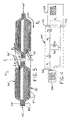
- a rotary transformer according to the present invention is generally designated with the numeral 50.
- the transformer 50 includes an outer cylindrical core 52 and an inner cylindrical core 54.
- the inner core serves as the rotating secondary core
- the outer core serves as the stationary primary core.
- this assumed configuration is strictly for convenience and ease of explanation, because clearly either core/winding can be the primary while the other core/winding serves as the secondary.
- either core can be rotated with respect to the other, although for higher speed operation it may be desirable to rotate the smaller diameter inner core only.
- the inner or secondary core 54 is generally cylindrical in shape and includes a longitudinally extended body 56 that flares out at both ends to enlarged outer diameter ear-like axial extensions 58.
- the flared portions 60 are preferred to a sharp angled radial extension (as in Fig. 1 for example) to facilitate manufacturing of the laminated cores.
- the flared portions 60 preferably include radius-type bends 62. An angle of thirty-one degrees (31°) has been found to be suitable for the flared portions, though this angle is not critical.
- the cores 52,54 are laminated structures, preferably having a plurality of thin laminations that extend along the centerline axis of rotation, and are stacked radially outward from the rotation axis.
- the inner core has a preferred flux direction that is generally axial as represented by the ⁇ , arrows in Fig. 3. It is apparent that the flux substantially remains within the core structure, of course, except where the flux crosses the air gap to the other core.
- the preferred flux direction in the ear-like extensions 58 is also axial. However, the flared portions 60 will direct the flux with both an axial and radial directional component.
- the laminations can be made of any suitable magnetically permeable material such as silicon iron, a nickel iron alloy such as Alloy 49, stainless steel, or cobalt iron alloy such as Vanadium Permendur, to name just a few.
- the particular material selected for the laminations will depend on such factors as the size and weight criteria the transformer must meet, as well as core losses allowable, permeability required, formability of the material, cost and the type of power transfer required from the primary to the secondary winding and the efficiency needed.
- the laminations can be made from concentrically formed rings or in a tape wound configuration. Other lamination techniques are certainly useable.
- a six pount (2.72 kg approximately) transformer capable of coupling from the primary to the secondary 300 to 500 watts from a 400 Hz source can be realized in an approximately two inch or 5cm. length by approximately nine inch (22,86cm) to 10.5 inch (26.67cm) diameter envelope using only a 0.056 (0.142cm) thick core made of four silicon iron laminations each 0.014 inch (0.0356cm) thick.
- the laminations can be bonded together with Bondmaster® or other suitable adhesive.
- a secondary winding or coil 64 is wrapped around the cylindrical body 56 between the flared portions 60.
- Lead wires 66 can be used to access the secondary winding after the transformer is fully assembled and preferably potted.
- the secondary leads 66 are connected to the deicing system which acts as the output load for the transformer. In such an example, the load rotates with the secondary and the prop.
- the secondary winding is a multi-turn coil made from insulated wire as is known generally in the transformer art.
- a thin insulating layer 68 such as Nomex® for example, is provided between the secondary winding 64 and the secondary core 54.
- the primary core 52 is similar to the secondary core 54, except that the core body flares inwardly to the ear-like extensions to a reduced diameter cylindrical shape. Accordingly, the primary core includes a longitudinally extended body 80 that flares in at both ends to reduced outer diameter ear-like axial extensions 82. Thus when viewed in longitudinal section as in Fig. 3 the primary core 52 also has somewhat of a stretched omega shaped contour. Similar to the secondary core, the flared portions 84 are preferred to a sharp angled radial extension. Thus, the flared portions 84 preferably include radius-type bends 86. As with the secondary core, an angle of thirty-one degrees (31°) has been found to be suitable for the flared portions 84.
- the primary core is also a laminated structure and thus has a preferred flux direction that is generally axial as represented by the arrow ⁇ p in Fig. 3.
- a primary winding or coil 88 is wrapped within the cylindrical body 80 between the flared portions 84.
- the primary winding 88 typically will include fewer turns of larger gauge wire than the secondary winding 64.
- a step-down transformer could of course also be used.
- the primary winding 88 can conveniently be formed on a mandrel and can hold its shape while being inserted into the interior of the primary core.
- the primary winding can be permanently held in place by potting compound or other suitable material when the transformer 50 is fully wound and assembled.
- Lead wires 90 can be used to access the secondary winding after the transfer is fully assembled and preferably potted.
- the primary leads 90 are connected to the power source from the engine power plant, such as for example, a 10-100 kVA supply operating at 400 hertz.
- the primary winding is a multi-turn coil made from insulated wire as is known generally in the transformer art.
- a thin insulating layer 92 which may conveniently be the same material as the layer 68, such as Nomex® for example, is provided between the primary winding 88 and the primary core 52.
- the outer diameter of the secondary core extensions 58 is slightly and uniformly undersized with respect to the inner diameter of the primary core extensions 82 so as to fit concentrically therein.
- This arrangement provides an airgap 94 between the cores and allows the secondary core and winding to freely spin or rotate within the primary core and winding on a common central longitudinal axis.
- a typical airgap for the exemplary transformer described herein would be approximately 0.050inch (0.127cm).
- Another feature is the provision of the axial ear-like extensions 58,82 on the secondary and primary cores respectively. These extensions serve several purposes, one of which is that they provide an enlarged airgap area for the flux to cross from the primary core to the secondary core. This increase in the airgap area reduces flux density in the airgap and reduces the magnetizing currents in the primary.
- extensions 58,82 allow for axial displacement between the primary and secondary cores without a significant increase in primary excitation current or loss of power from the primary to the secondary.
- vibration and axial displacement of the shaft can cause the secondary core to shift axially with respect to the primary core.
- the ear-like extensions maintain an adequate airgap area therebetween to insure that the power transformation from the primary to the secondary will not be unacceptably degraded.
- the extensions may have an axial length of about 0.195 inch (0.495cm), as compared to the core thickness of only about 0.060inch (0.152cm).
- extensions help spread the flux across a larger airgap area thus reducing flux crowding which will tend to occur near the areas 96 where the flux will prefer to cross over the airgap 94.
- laminated cores can be used to achieve a small envelope lightweight high power rotary transformer.
- the invention also contemplates an axial rotary transformer.
- the cores 52' and 54' are axially adjacent each other and separated by an airgap 94' between the extensions 58',82'.
- the basic omega-shaped core contour is still preferred, similar to that illustrated in Fig. 3.
- a rotary transformer 50' according to the present invention is shown in combination with an aircraft deicing system.
- the transformer 50' is represented by the electrical equivalent circuits as will be familiar to those skilled in the art.
- the outer primary winding which is stationary with respect to the secondary, is electrically connected to the aircraft engine power supply 100 by conductors 90'.
- the secondary core is attached to the drive shaft of the engine for rotation therewith (not shown), while the secondary winding is electrically connected to the deicing system circuitry 104 by the conductors 102.
- the engine power supply 100 provides the excitation current to the primary winding which induces a flux in the primary core of the transformer 50'.
- the deicing circuit is simply shown as a functional block because, as far as the transformer 50' is concerned, the deicing system is but one type of load that can be connected thereto.
- the deicing system may comprise a thermal deicing system that uses a steady supply of current to a resistive heater load or blanket.
- a thermal deicing system that uses a steady supply of current to a resistive heater load or blanket.
- Such a system is shown, for example, in US Pat. No. 4,386,749, the disclosure of which is fully incorporated herein by reference.
- Other deicing systems could also be used of course, such as for example, electro-mechanical systems including pneumatic, hydraulic, electric impulse, eddy current and electro-expulsive.
- Such deicing systems are known as in US Pat. Nos. 4,690,353; 4,875,644; 5,129,598 and 5,152,480, the disclosures of which are fully incorporated herein by reference. It is important to recognize, however, that aircraft deicing systems are but one type of load that can be used with the transformer of the present invention, and such exemplary description herein should not be construed in a limiting sense.
- the rotary transformer may be used to charge a capacitive load to about 240 volts at about 300 watts.
- the rotary transformer of the present invention thus provides a lightweight and efficient rotary power transformation capable of operating at high power without mechanical wear, thus obviating the prior need for brush or slip-ring assemblies.
Landscapes
- Engineering & Computer Science (AREA)
- Power Engineering (AREA)
- Coils Of Transformers For General Uses (AREA)
Applications Claiming Priority (2)
| Application Number | Priority Date | Filing Date | Title |
|---|---|---|---|
| US98220292A | 1992-11-25 | 1992-11-25 | |
| US982202 | 1997-12-01 |
Publications (1)
| Publication Number | Publication Date |
|---|---|
| EP0599604A1 true EP0599604A1 (fr) | 1994-06-01 |
Family
ID=25528933
Family Applications (1)
| Application Number | Title | Priority Date | Filing Date |
|---|---|---|---|
| EP93309333A Withdrawn EP0599604A1 (fr) | 1992-11-25 | 1993-11-23 | Transformateur rotatif |
Country Status (3)
| Country | Link |
|---|---|
| US (1) | US5572178A (fr) |
| EP (1) | EP0599604A1 (fr) |
| CA (1) | CA2109652A1 (fr) |
Families Citing this family (37)
| Publication number | Priority date | Publication date | Assignee | Title |
|---|---|---|---|---|
| TW416067B (en) | 1998-02-27 | 2000-12-21 | Tdk Corp | Pot-core components for planar mounting |
| US6483218B1 (en) * | 1999-05-20 | 2002-11-19 | Alex Petrinko | Brushless electric exciter for dynamoelectric machines |
| US6237861B1 (en) * | 1999-06-10 | 2001-05-29 | Thomas M. Northrop | Window deicer and anti-icer |
| US6630765B2 (en) * | 2001-01-31 | 2003-10-07 | Delphi Technologies, Inc. | Coil lead and terminal securement caps for securing wires of a rotor |
| DE10107577A1 (de) * | 2001-02-17 | 2002-09-26 | Bosch Gmbh Robert | Drehübertrager |
| DE10156212A1 (de) * | 2001-11-15 | 2003-06-05 | Siemens Ag | Vorrichtung zur elektrischen Versorgung wenigstens eines Supraleiters |
| US8350655B2 (en) * | 2003-02-26 | 2013-01-08 | Analogic Corporation | Shielded power coupling device |
| US9368272B2 (en) | 2003-02-26 | 2016-06-14 | Analogic Corporation | Shielded power coupling device |
| US9490063B2 (en) | 2003-02-26 | 2016-11-08 | Analogic Corporation | Shielded power coupling device |
| JP4292184B2 (ja) * | 2003-06-10 | 2009-07-08 | オーチス エレベータ カンパニー | ワイヤレスエレベータホール備品に有用な誘導結合電力 |
| DE10344055A1 (de) * | 2003-09-23 | 2005-04-21 | Siemens Ag | Induktiver Drehübertrager |
| US7724119B2 (en) * | 2005-05-03 | 2010-05-25 | Schleifring Und Apparatebau Gmbh | Inductive rotary joint comprising polymer material |
| EP1772940A3 (fr) * | 2005-10-04 | 2011-05-18 | Prüftechnik Dieter Busch AG | Coupleur rotatif pour la transmission d'énergie électrique ou information |
| US7355302B2 (en) * | 2005-11-23 | 2008-04-08 | Ice Corporation | System and method for providing power and control through a rotating interface |
| US7848482B2 (en) * | 2007-11-07 | 2010-12-07 | Kabushiki Kaisha Toshiba | X-ray CT device and method of manufacturing the same |
| JP2009231803A (ja) | 2008-02-29 | 2009-10-08 | Seiko Epson Corp | 回転装置およびロボットアーム装置 |
| GB2464945B (en) * | 2008-10-29 | 2013-07-10 | Wfs Technologies Ltd | Electrical connector system |
| CN102483989B (zh) * | 2009-07-03 | 2014-02-19 | 瑞士单浮筒系泊公司 | 高压电感应旋转装置 |
| FR2960516B1 (fr) * | 2010-05-28 | 2012-05-04 | Eurocopter France | Dispositif d'alimentation electrique et de controle d'un equipement d'un rotor, et aeronef muni d'un tel dispositif |
| US8405480B2 (en) * | 2010-12-09 | 2013-03-26 | General Electric Company | Electrical assembly for use with a rotary transformer and method for making the same |
| FR2990557B1 (fr) * | 2012-05-10 | 2015-05-01 | Hispano Suiza Sa | Transformateur tournant triphase cuirasse magnetiquement |
| FR2990812B1 (fr) * | 2012-05-16 | 2014-05-02 | Eurocopter France | Dispositif d'alimentation electrique d'au moins un equipement d'un rotor d'un aeronef, et aeronef |
| FR2994762B1 (fr) * | 2012-08-23 | 2015-11-20 | Hispano Suiza Sa | Transformateur tournant triphase-diphase a connexion scott |
| DE102013220207B4 (de) * | 2013-10-07 | 2019-10-24 | Siemens Healthcare Gmbh | Vorrichtung zum kontaktlosen Senden oder Empfangen elektrischer Leistung zwischen bewegten Teilen einer Röntgenbildgebungsanlage |
| DE102014212124B3 (de) * | 2014-06-24 | 2015-05-21 | Schaeffler Technologies AG & Co. KG | Übertrager, Verfahren zu dessen Herstellung und Wälzlager mit integriertem Übertrager |
| EP3035483B1 (fr) * | 2014-12-18 | 2018-04-25 | Schleifring GmbH | Joint rotatif inductif avec des noyaux de ferrite en forme de U |
| FR3036434B1 (fr) * | 2015-05-19 | 2019-11-08 | Safran Aircraft Engines | Assemblage sur un moteur, pouvant definir un dispositif d'essai en perte d'aube |
| US9889940B2 (en) * | 2016-02-16 | 2018-02-13 | Peter Lenkey | Deicing apparatuses comprising at least one standoff |
| FR3049759B1 (fr) * | 2016-03-30 | 2018-04-06 | Safran Electronics & Defense | Transformateur electrique a enroulements |
| FR3059043B1 (fr) | 2016-11-18 | 2018-12-14 | Safran Aircraft Engines | Turbomachine munie d'un transformateur triphase d'alimentation d'elements de degivrage electrique |
| FR3068195B1 (fr) | 2017-06-27 | 2019-07-19 | Airbus Helicopters | Procede de fabrication d'un equipement tournant de voilure tournante muni d'un degivreur, ledit equipement tournant et un drone muni dudit equipement tournant |
| EP3533522B1 (fr) * | 2018-02-28 | 2026-04-29 | Alfa Laval Corporate AB | Séparateur centrifuge et procédé de fonctionnement d'un séparateur centrifuge |
| FR3080944B1 (fr) | 2018-05-07 | 2020-05-22 | Safran Aircraft Engines | Ensemble propulsif pour aeronef muni d'un transformateur tournant d'alimentation des pales en energie electrique |
| FR3103308B1 (fr) * | 2019-11-20 | 2021-10-08 | Safran Aircraft Engines | Transformateur rotatif et machine tournante comportant un tel transformateur rotatif |
| EP3845460B1 (fr) * | 2019-12-30 | 2022-07-06 | LEONARDO S.p.A. | Rotor pour un aéronef apte au vol stationnaire |
| KR102684789B1 (ko) * | 2022-01-27 | 2024-07-11 | 이주열 | 비접촉식 회전 변압기 및 이를 포함하는 모터 |
| FR3163924A1 (fr) * | 2024-06-26 | 2026-01-02 | Safran Electrical & Power | Procédé de degivrage pour un turbopropulseur |
Citations (4)
| Publication number | Priority date | Publication date | Assignee | Title |
|---|---|---|---|---|
| FR863490A (fr) * | 1939-02-21 | 1941-04-02 | Thomson Houston Comp Francaise | Perfectionnements aux systèmes et aux dispositifs d'alimentation d'organes mobiles en énergie électrique |
| US3535618A (en) * | 1969-01-08 | 1970-10-20 | Superior Electric Co | Rotative inductive electrical coupling |
| DE2234472A1 (de) * | 1972-07-13 | 1974-01-24 | Siemens Ag | Transformator mit relativ zueinander rotierenden koaxialen eisenkoerpern mit darin angeordneten ringspulen |
| JPS6318610A (ja) * | 1986-07-11 | 1988-01-26 | Victor Co Of Japan Ltd | ロ−タリトランス |
Family Cites Families (5)
| Publication number | Priority date | Publication date | Assignee | Title |
|---|---|---|---|---|
| US3441887A (en) * | 1967-09-01 | 1969-04-29 | Caterpillar Tractor Co | High frequency rotary inductive coupling |
| DE2855379A1 (de) * | 1978-12-21 | 1980-07-03 | Siemens Ag | Roentgendiagnostikgeraet fuer die erzeugung von schichtbildern eines aufnahmeobjektes |
| US4321572A (en) * | 1980-11-13 | 1982-03-23 | The United States Of America As Represented By The Administrator Of The National Aeronautics And Space Administration | Non-contacting power transfer device |
| DE3503348C1 (de) * | 1985-02-01 | 1986-06-19 | Dr.Ing.H.C. F. Porsche Ag, 7000 Stuttgart | Ferromagnetischer Mehrfachschalenkern fuer elektrische Spulen |
| US5233324A (en) * | 1992-03-26 | 1993-08-03 | Eaton Corporation | Current transformer for sensing current in an electrical conductor |
-
1993
- 1993-11-22 CA CA002109652A patent/CA2109652A1/fr not_active Abandoned
- 1993-11-23 EP EP93309333A patent/EP0599604A1/fr not_active Withdrawn
-
1994
- 1994-02-16 US US08/197,776 patent/US5572178A/en not_active Expired - Lifetime
Patent Citations (4)
| Publication number | Priority date | Publication date | Assignee | Title |
|---|---|---|---|---|
| FR863490A (fr) * | 1939-02-21 | 1941-04-02 | Thomson Houston Comp Francaise | Perfectionnements aux systèmes et aux dispositifs d'alimentation d'organes mobiles en énergie électrique |
| US3535618A (en) * | 1969-01-08 | 1970-10-20 | Superior Electric Co | Rotative inductive electrical coupling |
| DE2234472A1 (de) * | 1972-07-13 | 1974-01-24 | Siemens Ag | Transformator mit relativ zueinander rotierenden koaxialen eisenkoerpern mit darin angeordneten ringspulen |
| JPS6318610A (ja) * | 1986-07-11 | 1988-01-26 | Victor Co Of Japan Ltd | ロ−タリトランス |
Non-Patent Citations (2)
| Title |
|---|
| PATENT ABSTRACTS OF JAPAN vol. 12, no. 225 (E - 626)<3072> 25 June 1988 (1988-06-25) * |
| W.MC LYMAN ET AL.: "rotary power transformer and inverter circuit", N.T.I.S. TECHNICAL NOTES, vol. B, no. 3, March 1986 (1986-03-01), SPRINGFIELD, US, pages 281 * |
Also Published As
| Publication number | Publication date |
|---|---|
| US5572178A (en) | 1996-11-05 |
| CA2109652A1 (fr) | 1994-05-26 |
Similar Documents
| Publication | Publication Date | Title |
|---|---|---|
| US5572178A (en) | Rotary transformer | |
| KR950010879B1 (ko) | 경량 고출력 전자기 변환기 | |
| US4363988A (en) | Induction disk motor with metal tape components | |
| RU2479880C2 (ru) | Сборка сверхпроводящих катушек и оборудование для генерирования магнитного поля | |
| US4481438A (en) | High voltage electrical generator and windings for use therein | |
| EP0199496B1 (fr) | Génératrice de réluctance variable à aimant permanent | |
| US5319844A (en) | Method of making an electromagnetic transducer | |
| KR100727294B1 (ko) | 변환기 | |
| DE202012012653U1 (de) | Elektrische Axialflussmaschine | |
| US20110037337A1 (en) | Rotary electromagnetic machines | |
| EP2377133B1 (fr) | Transformateur rotatif | |
| US4260925A (en) | Stator for an electromagnetic transducer | |
| WO1996012337A1 (fr) | Generatrice sans balais | |
| US20250300540A1 (en) | Torque dense electric motor | |
| US3317874A (en) | Rotating transformer | |
| EP1793467B1 (fr) | Dispositif électromécanique comportant des tôles de stator tridimensionnelles | |
| US12451781B2 (en) | Hybrid excited rotary machine | |
| EP4170869A1 (fr) | Moteur à flux axial à haute température et haute densité de puissance | |
| US4185216A (en) | Circumferentially-segmented magnet homopolar dynamoelectric machine | |
| US4581555A (en) | Homopolar dynamoelectric machine with a shielded stator excitation coil | |
| JPH05506979A (ja) | 電磁トランスジューサ用電機子の製造方法 | |
| EP2793375B1 (fr) | Stator pour une machine électrique d'une machine de travail mobile | |
| US12015316B2 (en) | High temperature and high power density axial flux motor | |
| US20220052572A1 (en) | Electric machine and hybrid electric vehicle | |
| JPWO2024009375A5 (fr) |
Legal Events
| Date | Code | Title | Description |
|---|---|---|---|
| PUAI | Public reference made under article 153(3) epc to a published international application that has entered the european phase |
Free format text: ORIGINAL CODE: 0009012 |
|
| AK | Designated contracting states |
Kind code of ref document: A1 Designated state(s): DE FR GB |
|
| 18D | Application deemed to be withdrawn |
Effective date: 19941202 |