EP0599627B1 - Méthode de contrÔle de la température d'un espace climatisé utilisant un cryogène - Google Patents
Méthode de contrÔle de la température d'un espace climatisé utilisant un cryogène Download PDFInfo
- Publication number
- EP0599627B1 EP0599627B1 EP93309365A EP93309365A EP0599627B1 EP 0599627 B1 EP0599627 B1 EP 0599627B1 EP 93309365 A EP93309365 A EP 93309365A EP 93309365 A EP93309365 A EP 93309365A EP 0599627 B1 EP0599627 B1 EP 0599627B1
- Authority
- EP
- European Patent Office
- Prior art keywords
- cryogen
- temperature
- heating
- heat exchanger
- air
- Prior art date
- Legal status (The legal status is an assumption and is not a legal conclusion. Google has not performed a legal analysis and makes no representation as to the accuracy of the status listed.)
- Expired - Lifetime
Links
Images

Classifications
-
- F—MECHANICAL ENGINEERING; LIGHTING; HEATING; WEAPONS; BLASTING
- F24—HEATING; RANGES; VENTILATING
- F24F—AIR-CONDITIONING; AIR-HUMIDIFICATION; VENTILATION; USE OF AIR CURRENTS FOR SCREENING
- F24F5/00—Air-conditioning systems or apparatus not covered by F24F1/00 or F24F3/00, e.g. using solar heat or combined with household units such as an oven or water heater
- F24F5/0007—Air-conditioning systems or apparatus not covered by F24F1/00 or F24F3/00, e.g. using solar heat or combined with household units such as an oven or water heater cooling apparatus specially adapted for use in air-conditioning
- F24F5/0017—Air-conditioning systems or apparatus not covered by F24F1/00 or F24F3/00, e.g. using solar heat or combined with household units such as an oven or water heater cooling apparatus specially adapted for use in air-conditioning using cold storage bodies, e.g. ice
-
- B—PERFORMING OPERATIONS; TRANSPORTING
- B60—VEHICLES IN GENERAL
- B60H—ARRANGEMENTS OF HEATING, COOLING, VENTILATING OR OTHER AIR-TREATING DEVICES SPECIALLY ADAPTED FOR PASSENGER OR GOODS SPACES OF VEHICLES
- B60H1/00—Heating, cooling or ventilating devices
- B60H1/32—Cooling devices
- B60H1/3202—Cooling devices using evaporation, i.e. not including a compressor, e.g. involving fuel or water evaporation
-
- F—MECHANICAL ENGINEERING; LIGHTING; HEATING; WEAPONS; BLASTING
- F25—REFRIGERATION OR COOLING; COMBINED HEATING AND REFRIGERATION SYSTEMS; HEAT PUMP SYSTEMS; MANUFACTURE OR STORAGE OF ICE; LIQUEFACTION SOLIDIFICATION OF GASES
- F25D—REFRIGERATORS; COLD ROOMS; ICE-BOXES; COOLING OR FREEZING APPARATUS NOT OTHERWISE PROVIDED FOR
- F25D29/00—Arrangement or mounting of control or safety devices
- F25D29/001—Arrangement or mounting of control or safety devices for cryogenic fluid systems
-
- B—PERFORMING OPERATIONS; TRANSPORTING
- B60—VEHICLES IN GENERAL
- B60H—ARRANGEMENTS OF HEATING, COOLING, VENTILATING OR OTHER AIR-TREATING DEVICES SPECIALLY ADAPTED FOR PASSENGER OR GOODS SPACES OF VEHICLES
- B60H1/00—Heating, cooling or ventilating devices
- B60H1/00642—Control systems or circuits; Control members or indication devices for heating, cooling or ventilating devices
- B60H1/00814—Control systems or circuits characterised by their output, for controlling particular components of the heating, cooling or ventilating installation
- B60H1/00878—Control systems or circuits characterised by their output, for controlling particular components of the heating, cooling or ventilating installation the components being temperature regulating devices
- B60H2001/00961—Control systems or circuits characterised by their output, for controlling particular components of the heating, cooling or ventilating installation the components being temperature regulating devices comprising means for defrosting outside heat exchangers
-
- Y—GENERAL TAGGING OF NEW TECHNOLOGICAL DEVELOPMENTS; GENERAL TAGGING OF CROSS-SECTIONAL TECHNOLOGIES SPANNING OVER SEVERAL SECTIONS OF THE IPC; TECHNICAL SUBJECTS COVERED BY FORMER USPC CROSS-REFERENCE ART COLLECTIONS [XRACs] AND DIGESTS
- Y02—TECHNOLOGIES OR APPLICATIONS FOR MITIGATION OR ADAPTATION AGAINST CLIMATE CHANGE
- Y02E—REDUCTION OF GREENHOUSE GAS [GHG] EMISSIONS, RELATED TO ENERGY GENERATION, TRANSMISSION OR DISTRIBUTION
- Y02E60/00—Enabling technologies; Technologies with a potential or indirect contribution to GHG emissions mitigation
- Y02E60/14—Thermal energy storage
Definitions
- the invention relates in general to air conditioning and refrigeration systems, and more specifically to the use of a cryogen for controlling the temperature of a conditioned space of stationary and transport type applications of air conditioning and refrigeration systems.
- Stationary and transport applications of air conditioning and transport refrigeration systems control the temperature of a conditioned space to a predetermined temperature range adjacent to a predetermined set point temperature, with transport applications including those used with straight trucks, tractor-trailer combinations, refrigerated containers, and the like.
- Such air conditioning and refrigeration systems conventionally utilize a chlorofluorocarbon (CFC) refrigerant in a mechanical refrigeration cycle.
- the mechanical refrigeration cycle requires a refrigerant compressor driven by a prime mover, which often includes an internal combustion engine, such as a diesel engine. Because of the suspected depleting effect of CFC's on stratospheric ozone (O 3 ), practical alternatives to the use of CFC's in air conditioning and refrigeration systems are being sought.
- CFC chlorofluorocarbon
- cryogen ie., a gas which has been compressed to a very cold liquid state, such as carbon dioxide (CO 2 ) and nitrogen (N 2 ), in air conditioning and refrigeration systems is particularly attractive because, in addition to eliminating the need for a CFC, it also eliminates the need for a compressor and associated prime mover.
- liquid nitrogen refrigeration system of this document directs liquid nitrogen into primary coils of an evaporator.
- the output of the evaporator coils, which is vaporized liquid nitrogen is passed through an air motor which drives a fan which circulates air between the evaporator and a cargo space.
- the vaporized nitrogen from the air motor is directed into secondary coils of the evaporator, and the vaporized nitrogen is then exhausted to the atmosphere.
- liquid nitrogen is vaporized in an ambient air heat exchanger and then passed through a heating device which includes a burner.
- the heated nitrogen which is heated to 538°C (1000°F) is then directed through the evaporator and the air motor. If the heat cycle was initiated by a signal to defrost the evaporator, the defrost cycle is terminated as a function of a predetermined relationship between the temperature of the discharge air and the temperature of the nitrogen being exhausted to the atmosphere.
- the present invention consists in a method for controlling the temperature of a conditioned space comprising the steps of
- conditioned space includes any space to be temperature and/or humidity controlled, including stationary and transport applications for the preservation of foods and other perishables, maintenance of a proper atmosphere for the shipment of industrial products, space conditioning for human comfort, and the like.
- the term “refrigeration system” is used to generically cover both air conditioning systems for human comfort, and refrigeration systems for preservation of perishables and shipment of industrial products. Also, when it is stated that the temperature of a conditioned space is controlled to a selected set point temperature, it is to be understood that the temperature of the conditioned space is controlled to a predetermined temperature range adjacent to the selected set point temperature.
- valves which are normally open are illustrated with an empty circle
- valves which are normally closed are illustrated with an "X" within a circle.
- electrical control the associated electrical or electronic control, hereinafter called “electrical control”
- An arrow pointed at a valve in the Figures indicates that the valve is, or may be, controlled by the electrical control.
- the invention is suitable for use when a refrigeration system is associated with a single conditioned space to be controlled to a selected set point temperature; and, the invention is also suitable for use when a refrigeration system is associated with a compartmentalized application, ie., a conditioned space is divided into at least first and second separate conditioned spaces to be individually controlled to selected set point temperatures.
- a compartmentalized application for example, one conditioned space may be used to condition a frozen load, and the other a fresh load, or combinations thereof, as desired.
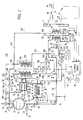
- FIG. 1 there is shown a refrigeration system 10 suitable for use with any conditioned space, and particularly well suited for use on straight trucks, tractor-trailer combinations, containers, and the like, with the word “vehicle” being used to generically refer to the various transport vehicles which utilize refrigeration systems.
- Refrigeration system 10 may be used in stationary and transport applications, with reference 12 generally indicating a vehicle in a transport application, and an enclosure wall in a stationary application. Refrigeration system 10 may be used to condition a single conditioned space 14 to be conditioned to a predetermined set point temperature, and also to condition two or more separate conditioned spaces to selected set point temperatures. For purposes of example only, the embodiments of the invention set forth in the Figures illustrate refrigeration system 10 controlling the temperature of a single conditioned space 14.
- refrigeration system 10 includes a vessel 16 containing a suitable cryogen, such as nitrogen (N 2 ), or carbon dioxide (CO 2 ), for example, with a liquid phase thereof being indicated at 18, and with a vapor phase, located above the liquid level, being indicated at 20.
- Vessel 16 may be filled, for example, by connecting a ground support apparatus, indicated generally at 22, to a supply line or conduit 24 which includes a valve 26.
- Vapor pressure in vessel 16 is maintained above a predetermined pressure by a pressure regulating arrangement 28 connected between lower and upper points of vessel 16 via conduits 30 and 31, respectively.
- the pressure in vessel 16 must be maintained above the triple point for CO 2 , ie., 518 kPa (75.13 psia).
- a valve 32, a vaporizing coil 34, and a valve 36 are connected between conduits 30 and 31.
- Valve 32 opens when the pressure in vessel 16 falls to a predetermined value, admitting liquid cryogen into vaporizing coil 34.
- Vaporizing coil 34 is exposed to ambient temperature outside of vehicle 12.
- Pressure regulating valve 36 maintains the vapor pressure in vessel 16 at a predetermined level selected for optimal system operation and/or to prevent the formation of CO 2 slush in vessel 16 when the cryogen is CO 2 .
- a pressure reading safety valve 38 is provided in conduit 30 at a point where the vapor pressure in vessel 16 may be directly sensed.
- a venting valve 40 is also provided to facilitate the filling process.
- vessel 16 may be filled with CO 2 at an initial pressure of about 100 psia and an initial temperature of about -58°F (-50°C).
- initial pressure about 2068 kPa (300 psia) and an initial temperature of about 0°F (-17.8°C).
- a first cryogen fluid flow path 42 is provided which draws liquid cryogen 18 from vessel 16 via a conduit 44.
- Conduit 44 extends from a low point of vessel 16 to a tee 46.
- the first flow path 42 continues from tee 46 to a first heat exchanger 48 via a conduit 50 which includes a flow regulating valve 52 and a tee 54.
- the first flow path 42 continues from the first heat exchanger 48 to air mover means 56.
- Air mover means 56 draws air from conditioned space 14 into an air conditioning means or apparatus 58, which includes the first heat exchanger 48.
- Conditioned air is discharged back into conditioned space 14 by air mover means 56.
- Air mover means 56 includes a fan or blower 60 which is driven by vaporized cryogen in a suitable vapor driven motor or turbine 62, which will hereinafter be referred to as vapor driven motor 62.
- the first heat exchanger 48 is dimensioned and configured, and the flow rate of the cryogen adjusted via flow regulating valve 52, to completely vaporize the liquid cryogen 18, and thus vaporized cryogen is provided at an exit end of heat exchanger 48.
- the first flow path 42 continues from heat exchanger 48 to an input of vapor driven motor 62 via a conduit 64 which includes a back pressure regulating valve 66 and an expansion valve 68.
- Expansion valve 68 which isenthalpically expands the vaporized cryogen before being directed to the vapor operated motor 62, may have a manually adjustable orifice, or the orifice size may be controlled by electrical control 70.
- Vapor driven motor 62 isentropically expands the vaporized cryogen, driving fan 60 while reducing the pressure and temperature of the cryogen.
- An output of vapor driven motor 62 is connected to a second heat exchanger 74 associated with air conditioning apparatus 58 via a conduit 76, continuing the first flow path 42.
- the first flow path 42 then continues from the output of the second heat exchanger 74 via a conduit 77 to a tee 78.
- the second heat exchanger 74 could be associated with a second conditioned space having a set point temperature above the set point temperature of conditioned space 14, for example.
- the first flow path 42 to this point of the description may provide a cooling cycle for conditioned space 14, when the temperature of conditioned space 14 is above a predetermined narrow temperature band relative to a set point temperature selected via a set point temperature selector 80.
- Flow regulating feed valve 52 is controlled by electrical control 70 as a function of system conditions at any instant. For example, flow regulating valve 52 may be controlled as a function of the desired set point temperature, the actual temperature of conditioned space 14, and the ambient temperature.
- the temperature of conditioned space 14 is sensed by either, or both, return air and discharge air temperature sensors 82 and 84. Temperature sensor 82 senses the temperature of air returning to the air conditioning apparatus 58, with the return air being indicated by arrow 86. Temperature sensor 84 senses the temperature of air being discharged from air conditioning apparatus 58, with the discharge air being indicated by arrow 88. The temperature of the ambient air is sensed by an ambient air temperature sensor 90. The conditioned air 88, which results from the heat exchange relation between the return air 86 and heat exchangers 48 and 74, is discharged back into conditioned space 14.
- Refrigeration system 10 may be used in combination with arrangements which do inject CO 2 into a conditioned space for fast temperature pull down and/or for load preservation. In such combined applications vessel 16 may be used as the source of the CO 2 .
- a temperature sensor 92 is disposed to sense the surface temperature of heat exchanger 48 at a location at or near the exit end of heat exchanger 48 to detect when evaporation may not be 100%, such as when surface ice builds up on heat exchanger 48. Thus, temperature sensor 92 may be used to enable electrical control 70 to trigger a defrost mode or cycle.
- Electrical control 70 subtracts the temperature of conditioned space 14, as indicated by the return air sensor 82, for example, from the set point temperature selected via set point selector 80, to provide a ⁇ T which is negative when the temperature of the conditioned space 14 is above set point, and positive when it is below set point.
- a negative ⁇ T triggers a cooling cycle, which results in controlling the flow of liquid cryogen 18 from vessel 16 through the first flow path 42 which includes the first and second heat exchangers 48 and 74.
- a positive ⁇ T triggers a heating cycle, and, as just mentioned, a heating cycle may also be triggered by defrost sensing means, such as the coil temperature sensor 92, or a timer, to melt water ice which may build up on heat exchangers 48 and 74 during a cooling cycle.
- defrost sensing means such as the coil temperature sensor 92, or a timer
- a heating cycle is implemented by a second cryogen flow path 94 which is connected between tees 46 and 54.
- the second cryogen flow path 94 includes cryogen heating means 96 and cryogen pre-heating means 98.
- Cryogen heating means 96 includes a heat exchanger coil 100 connected in the second cryogen flow path 94 via conduits 102 and 104, with conduit 102 connecting heat exchanger coil 100 to the cryogen pre-heating means 98 via a flow regulating valve 106, and with conduit 104 connecting heat exchanger coil 100 to tee 54.
- Heating means 96 includes a fuel supply 108 connected to a burner 110 via a conduit 112 which includes a valve 114.
- the fuel from fuel supply 108 may include liquefied natural gas, propane, diesel fuel, and the like. In a stationary application, other heat sources may be used to heat the cryogen, including electrical, hot liquids, steam, waste gases, and the like.
- control 70 opens valve 114, while simultaneously igniting burner 110.
- a controllable defrost damper 115 may be provided, with damper 115 being closed during a defrost cycle, to prevent warm air from being discharged into conditioned space 14.
- Preheating means 98 in this embodiment of the invention, includes first and selectable parallel flow paths 116 and 118, connected between tees 120 and 122.
- Tee 120 is connected to the first flow path 42 at tee 46, and tee 122 is connected to heating means 96.
- the first parallel flow path 116 includes an ambient loop 124 connected between tees 120 and 122 via a conduit 126 which includes a valve 128.
- Ambient loop 124 is disposed to expose any cryogen flowing therethrough to the ambient temperature, pre-heating the liquid cryogen 18 and vaporizing at least a portion thereof, before the cryogen reaches heating means 96.
- the second parallel flow path 118 includes heat exchanger means 130 disposed outside conditioned space 14, with heat exchanger means 130 comprising a heat exchanger coil 132 surrounded by a housing 134.
- Heat exchanger coil 132 is connected between tees 120 and 122 via a conduit 136 which includes a valve 138.
- Housing 134 includes an input 140 and an output 142.
- Pre-heating means 98 is provided in order to conserve as much of the fuel supply 108 during a heating cycle as possible, with it being common to provide an ambient loop 124 for pre-heating cryogen prior to heating cryogen with fuel burned in a burner 110. There are many instances in the winter when the ambient temperature provides very little pre-heating.
- the heated cryogen in a heating cycle even after traversing both the first and second heat exchangers 48 and 74, is often well above freezing, with the temperature depending upon the temperature of the conditioned space 14.
- the present invention utilizes the heated cryogen, after it has traversed heat exchangers 48 and 74, to aid the pre-heating means 98 in adding heat to the cryogen, when the temperature of the cryogen at this point of the flow path exceeds the ambient temperature.
- a temperature sensor 144 is disposed to sense the temperature of the cryogen as it exits the second heat exchanger 74, providing this information for electrical control 70, which then compares the temperature sensed by sensor 144 with the ambient temperature sensed by ambient temperature sensor 90. When the temperature of the ambient air exceeds the temperature of the cryogen exiting the second heat exchanger 74, control 70, during a heating cycle, opens valve 128 to direct liquid cryogen 18 through the first parallel path 116. When the temperature of the ambient air is less than the temperature of the cryogen exiting the second heat exchanger 74, electrical control 70 opens valve 138 to direct liquid cryogen 18 through heat exchanger coil 132.
- the cryogen exiting the second heat exchanger 74 is connected to tee 78 via conduit 77, with one side of tee 78 being connected to an exhaust conduit 146 via a valve 148.
- the remaining side of tee 78 is connected to the input 140 of heat exchanger housing 130 via a conduit 150 which includes a valve 152.
- the temperature of the cryogen exiting the second heat exchanger 74 may be lower than the ambient temperature, and thus ambient loop 124 would be initially selected to perform the pre-heating.
- Control 70 would then close valves 128 and 148, and open valve 138, to switch the cryogen preheat arrangement from path 116 to path 118, to utilize heated cryogen to perform the pre-heating.
- cryogen flow through the air mover means 56 is determined by the amount of cryogen flowing through the heat exchangers 48 and 74 at any instant.
- control 70 could, as an option, cycle between cooling and heating cycles to maintain set point with air circulation; or, as will be hereinafter described, an independent flow path may be provided for vapor motor 62 which by-passes the heat exchangers to provide a null cycle with air flow.
- Figure 2 is a diagrammatic representation of a refrigeration system 178. It illustrates an arrangement which provides independent control over the air mover means 56, providing any desired air movement volume in conditioned space 14 regardless of the amount of cryogen flowing through the heat exchangers 48 and 74. The illustrated arrangement also permits operation of air mover means 56 with zero flow of cryogen through the heat exchangers 48 and 74, permitting a null cycle to be initiated when the temperature of conditioned space 14 is "satisfied", ie, requiring neither a cooling nor a heating cycle to hold the temperature of conditioned space 14 within a "null" temperature band adjacent to the selected set point temperature.
- Figure 2 also illustrates an embodiment of the present invention which, similar to the Figure 1 embodiment utilizes "spent" cryogen in a cryogen pre-heating arrangement, while combining the two pre-heating means 116 and 118 of the Figure 1 embodiment.
- a second cryogen flow path 180 connected between tees 46 and 54 of the first cryogen flow path 42, comprises a conduit 181 which includes a valve 182, a pre-heating means 184, the heating means 96, which may identical to the pre-heating means of Figure 1, or, as will be hereinafter explained, modified to include an additional heat exchanger coil 186, a tee 188, and a valve 190.
- the air mover means 56 in this embodiment is moved to the end of the normal cryogen flow path, ie., instead of being disposed between heat exchangers 48 and 74, air mover means 56 is moved downstream from the two heat exchangers, and heat exchangers 48 and 74 are connected together via the hereinbefore mentioned back pressure regulating valve 66 and expansion valve 68.
- the second heat exchanger 74 may be selectively added to, and removed from, the cryogen flow path via a conduit 192, which includes a valve 194, and two tees 196 and 198 which are respectively located on the upstream and downstream sides of the second heat exchanger 74.
- a valve 200 is also provided between tee 196 and the input side of the second heat exchanger 74.
- electrical control 70 may operate both heat exchangers 48 and 74, or only heat exchanger 48, as dictated by the magnitude of ⁇ T.
- Tee 198 on the downstream side of the second heat exchanger 74 is connected to the hereinbefore mentioned heat exchanger coil 186 via a conduit 202 and a check valve 203.
- Heat exchanger coil 186 may be heated by heating means 96, as illustrated, or by a separate burner and valve connected to fuel supply 108, as desired.
- the output of heat exchanger coil 186 is connected to the input of vapor motor 62 via a conduit 204, which includes a tee 206.
- a conduit 208 having a valve 210 interconnects tees 188 and 206.
- the pre-heating means 184 includes an ambient loop or heat exchanger 212 surrounded by a housing 214.
- Housing 214 has two selectable configurations provided by controllable shutters 216.
- Heat exchanger coil 212 is located such that air flow may flow freely through housing 214, and about heat exchanger coil 212, when shutters 216 are open.
- housing 214 defines a substantially closed structure surrounding heat exchanger coil 212, including an input conduit 218 and an exhaust conduit 220.
- a normal exhaust conduit 222 exiting vapor motor 62 is modified to include a tee 224.
- One branch of tee 224 includes a valve 226 and an exhaust conduit 228, and the remaining branch of tee 224 is connected to the input conduit 218 of pre-heater housing 214 via a conduit 230 which includes a valve 232.
- the temperature of the cryogen exiting vapor motor 62 is sensed by a temperature sensor 234.
- valve 182 is closed and valve 52 controls the rate of liquid cryogen 18 flowing to the first heat exchanger 48.
- both heat exchangers 48 and 74 will normally be used. If the vapor entering vapor motor 62 does not have sufficient energy to provide the desire air flow rate in conditioned space 14, then energy may be added to the vapor by igniting burner 110 via control 70.
- valve 200 may be closed and valve 194 opened, to reduce the cooling rate of conditioned space 14 by removing the second heat exchanger 74 from the active cryogen flow path, while providing higher pressure cryogen for driving vapor motor 62.
- a null cycle may be initiated which requires zero cryogen flow through heat exchangers 48 and 74. If the load in conditioned space 14 requires air circulation, valves 52 and 190 are closed, and valves 182, 210 and 114 are opened, directing heated cryogen directly to vapor motor 62 for independent operation thereof.
- Electrical control 70 compares the temperature of the cryogen exiting vapor motor 62, as sensed by sensor 234, with the temperature of the ambient air, as sensed by sensor 90. Electrical control 70 opens shutters 216 and exhausts the cryogen to the atmosphere via valve 228 and exhaust conduit 228, when the ambient temperature is higher than the temperature of the cryogen. Electrical control 70 closes shutters 216 and directs the cryogen from vapor motor 62 to housing 214 by opening valve 232 and closing valve 226, when the temperature of the cryogen exceeds ambient temperature.
- valve 210 is closed and valve 190 is opened, to direct the heated cryogen through the first heat exchanger 48, and optionally through the second heat exchanger 74.
- the magnitude of the positive ⁇ T may be used to determine if one or both of the heat exchangers 48 and 74 should be active.
- the cryogen exiting tee 198 will be heated again if heat exchanger coil 186 is heated by heating means 96.
- control 70 will make a decision as to whether the cryogen needs additional heat to provide the fan horsepower necessary to obtain the desired air flow in conditioned space 14.
- Control 70 continuously compares the temperature of the cryogen exiting vapor motor 62 with ambient temperature, pre-heating the cryogen with ambient air, or by the cryogen exiting vapor motor 62, whichever is warmer.
- a defrost cycle to defrost heat exchangers 48 and 74 is similar to the heating cycle just described, except valve 200 would always be open and valve 194 would always be closed, to directly heat both heat exchangers 48 and 74 and thus minimize defrost time.
- Defrost damper 115 would also be closed during a defrost cycle.
- a valve arrangement located at the entrance of vapor motor 62 may be provided to divert the cryogen exiting heat exchanger 74 away from heat exchanger 86 and vapor motor 62 and into conduit 230, to simultaneously stop vapor motor 62 during the defrost cycle, and aid the pre-heat means 184.
- conduits 31 and 202 may be provided with tees 236 and 238, respectively, and a conduit 240 connected therebetween which includes a valve 242, a pressure regulating valve 244, and a check valve 246.
- vaporized cryogen by vaporizing coil 34 may be enhanced by providing a housing 250 about coil 34 having inlet and outlets, and directing either warm expended cryogen to inlet 252, when cryogen exiting vapor motor 62 exceeds ambient temperature, or directing hot gases produced by burner 110 to inlet 252.
- conduit 230 may be connected to inlet 252 via a conduit 253, shown in phantom, and in the latter arrangement a housing 256 is provided to collect hot gases from burner 110, and a conduit 258 is connected from housing 256 to inlet 252 of housing 250.
- pressure build-up coil 34 may not be able to maintain the desired pressure in vessel 16. In such a case, warmer exhaust cryogen or combustion gases may be used to assist pressure build-up coil 34 to build up to, and maintain, the desired pressure.
- Arrangement 259 provides a separate flow path to compensate for excessive pressure drop due to reasons such as the length of the flow conduits and heat exchanger coils.
- Arrangement 259 includes a conduit 260 which taps an upper point of vessel 16, or conduit 31, and a pressure regulator valve 262 which regulates the pressure in the flow paths to a predetermined pressure, or which is controlled to a selected pressure by electrical control 70, as desired.
- a check valve 264 is illustrated, but may be unnecessary as the vapor pressure in vessel 16 should always be higher than the pressure at a flow path point.
- a valve 266 may also be added to conduit 260, which is controlled by electrical control 70.
- Conduit 260 may have a smaller opening diameter than the main flow conduits.
- the flow paths may be tapped and connected to the pressure maintaining arrangement 259 where necessary, such as indicated by the arrow heads at the ends of broken lines.
- the pressure maintaining arrangement 259 may be combined with the flow path which includes conduit 240, to reduce piping, fittings and controls.
- a pressure relief valve should be added at any location where cryogen may be trapped between two valves at shut down.
- blowers and/or fans driven by electrical motors powered by the vehicle electrical system, or other suitable source may augment and/or replace the vapor motors, for moving air between the conditioned spaces and the associated heat exchangers. This is also applicable to stationary applications, with electrical mains being used to power electrical motors connected to fans and/or blowers. Also, in transport applications, the vapor motors may drive electrical generators or alternators for the purpose of charging batteries associated with the refrigeration system control 70.
Landscapes
- Engineering & Computer Science (AREA)
- Mechanical Engineering (AREA)
- Chemical & Material Sciences (AREA)
- Combustion & Propulsion (AREA)
- General Engineering & Computer Science (AREA)
- Physics & Mathematics (AREA)
- Thermal Sciences (AREA)
- Life Sciences & Earth Sciences (AREA)
- Sustainable Development (AREA)
- Thermotherapy And Cooling Therapy Devices (AREA)
- Heat-Exchange Devices With Radiators And Conduit Assemblies (AREA)
- Filling Or Discharging Of Gas Storage Vessels (AREA)
Claims (12)
- Procédé de réglage de la température d'un espace conditionné (14), comprenant les étapes suivantes :caractérisé par une étape d'utilisation (77, 152, 134 ; 222, 232, 230) de la matière cryogénique chauffée dans l'étape de chauffage afin que l'étape de préchauffage soit favorisée par addition de chaleur à la matière cryogénique, selon une condition prédéterminée.la mise à disposition d'une réserve (16) d'une matière cryogénique qui comprend une matière cryogénique (18) à l'état liquide,la disposition d'un trajet (42) de circulation de fluide destiné à la matière cryogénique,le montage d'un dispositif échangeur de chaleur (48) dans le trajet de circulation,le déplacement (56) d'air provenant de l'espace conditionné en relation d'échange de chaleur avec le dispositif échangeur de chaleur,le montage d'un dispositif de chauffage (96) dans le trajet de circulation,le chauffage (110) de la matière cryogénique à l'aide du dispositif de chauffage en fonction d'une condition prédéterminée,le montage d'un dispositif de préchauffage (98) de la matière cryogénique, etla vaporisation de la matière cryogénique liquide à l'aide du dispositif de préchauffage afin que l'étape de chauffage soit facilitée,
- Procédé selon la revendication 1, dans lequel l'étape d'utilisation de la matière cryogénique chauffée pour favoriser l'étape de vaporisation comprend des étapes de prélèvement de matière cryogénique à un emplacement qui est en aval du dispositif échangeur de chaleur, et la direction (152, 150) de la matière cryogénique vers le dispositif de préchauffage.
- Procédé selon la revendication 1, comprenant des étapes de mesure (144) de la température de la matière cryogénique en aval du dispositif échangeur de chaleur pour la création d'une première température, de mesure (90) de la température ambiante pour la création d'une seconde température, et de comparaison de la première et de la seconde température, la condition prédéterminée qui déclenche l'utilisation de la matière cryogénique chauffée pour favoriser l'étape de vaporisation étant le fait que la première température dépasse la seconde température.
- Procédé selon la revendication 3, comprenant une étape d'utilisation (128, 126, 124) de l'air ambiant pour favoriser l'étape de vaporisation lorsque la première température ne dépasse pas la seconde température.
- Procédé selon la revendication 1, comprenant une étape de montage d'un dispositif (62) à moteur entraíné par la vapeur dans le trajet de circulation pour l'exécution de l'étape de déplacement d'air de l'espace conditionné en relation d'échange de chaleur avec le dispositif échangeur de chaleur, l'étape d'utilisation de la matière cryogénique chauffée pour favoriser l'étape de vaporisation utilisant la matière cryogénique en aval du dispositif à moteur entraíné par la vapeur.
- Procédé selon la revendication 5, comprenant des étapes de mesure (144) de la température de la matière cryogénique en aval du dispositif à moteur entraíné par la vapeur pour la formation d'une première température, de mesure (90) de la température ambiante pour la formation d'une seconde température, et de comparaison de la première et de la seconde température, la condition prédéterminée qui déclenche l'utilisation de la matière cryogénique chauffée pour favoriser l'étape de vaporisation étant le fait que la première température dépasse la seconde température.
- Procédé selon la revendication 6, comprenant l'étape d'utilisation (128) de l'air ambiant pour favoriser l'étape de vaporisation lorsque la première température ne dépasse pas la seconde température.
- Procédé selon la revendication 5, dans lequel l'étape de montage du dispositif de chauffage (96) dans le trajet de circulation (42) comprend l'étape de positionnement du dispositif de chauffage en aval du dispositif échangeur de chaleur et en amont du dispositif à moteur entraíné par la vapeur.
- Procédé selon la revendication 8, comprenant l'étape de détection (248) de la nécessité de l'augmentation du débit d'air donné par l'étape de déplacement d'air, et dans lequel une condition prédéterminée qui déclenche le chauffage de la matière cryogénique par le dispositif de chauffage est la détection de la nécessité de l'augmentation de la circulation d'air.
- Procédé selon la revendication 1, dans lequel l'étape de montage d'un dispositif de chauffage dans le trajet de circulation comprend l'étape de positionnement du dispositif de montage en amont du dispositif échangeur de chaleur.
- Procédé selon la revendication 1, comprenant l'étape de détection (92) de la nécessité du dégivrage du dispositif échangeur de chaleur, et dans lequel :une condition prédéterminée qui déclenche le chauffage de la matière cryogénique par l'intermédiaire du dispositif de chauffage est la détection de la nécessité du dégivrage du dispositif échangeur de chaleur.
- Procédé selon la revendication 1, comprenant l'étape de conditionnement d'air de l'espace conditionné dans une bande prédéterminée de température adjacente à une température prédéterminée de point de consigne (80), et une condition prédéterminée qui déclenche le chauffage de la matière cryogénique par l'intermédiaire du dispositif de chauffage est le fait que la température de l'espace conditionné (14) est inférieure à la bande prédéterminée de température.
Applications Claiming Priority (2)
| Application Number | Priority Date | Filing Date | Title |
|---|---|---|---|
| US982333 | 1992-11-27 | ||
| US07/982,333 US5267446A (en) | 1992-11-27 | 1992-11-27 | Air conditioning and refrigeration systems utilizing a cryogen |
Publications (2)
| Publication Number | Publication Date |
|---|---|
| EP0599627A1 EP0599627A1 (fr) | 1994-06-01 |
| EP0599627B1 true EP0599627B1 (fr) | 1999-10-27 |
Family
ID=25529052
Family Applications (1)
| Application Number | Title | Priority Date | Filing Date |
|---|---|---|---|
| EP93309365A Expired - Lifetime EP0599627B1 (fr) | 1992-11-27 | 1993-11-24 | Méthode de contrÔle de la température d'un espace climatisé utilisant un cryogène |
Country Status (6)
| Country | Link |
|---|---|
| US (1) | US5267446A (fr) |
| EP (1) | EP0599627B1 (fr) |
| JP (1) | JPH06235563A (fr) |
| CA (1) | CA2110105C (fr) |
| DE (1) | DE69326869T2 (fr) |
| MX (1) | MX9307303A (fr) |
Families Citing this family (21)
| Publication number | Priority date | Publication date | Assignee | Title |
|---|---|---|---|---|
| US5267443A (en) * | 1992-11-27 | 1993-12-07 | Thermo King Corporation | Air conditioning and refrigeration methods and apparatus utilizing a cryogen |
| US5365744A (en) * | 1993-11-08 | 1994-11-22 | Thermo King Corporation | Air conditioning and refrigeration systems utilizing a cryogen |
| US5582015A (en) * | 1994-12-27 | 1996-12-10 | Ecometrics Corp. | Liquid nitrogen capillary heat exchanger |
| US5730216A (en) * | 1995-07-12 | 1998-03-24 | Thermo King Corporation | Air conditioning and refrigeration units utilizing a cryogen |
| US5598709A (en) * | 1995-11-20 | 1997-02-04 | Thermo King Corporation | Apparatus and method for vaporizing a liquid cryogen and superheating the resulting vapor |
| US5916246A (en) * | 1997-10-23 | 1999-06-29 | Thermo King Corporation | System and method for transferring liquid carbon dioxide from a high pressure storage tank to a lower pressure transportable tank |
| US6408632B1 (en) | 2000-06-28 | 2002-06-25 | Michael D. Cashin | Freezer and plant gas system |
| US6751966B2 (en) * | 2001-05-25 | 2004-06-22 | Thermo King Corporation | Hybrid temperature control system |
| DE10224724A1 (de) * | 2001-06-04 | 2003-01-30 | Thermo King Corp | Steuerverfahren für ein CRYO-Kühlsystem mit Eigenantrieb |
| US6631621B2 (en) * | 2001-07-03 | 2003-10-14 | Thermo King Corporation | Cryogenic temperature control apparatus and method |
| US6698212B2 (en) * | 2001-07-03 | 2004-03-02 | Thermo King Corporation | Cryogenic temperature control apparatus and method |
| KR100440300B1 (ko) * | 2001-10-08 | 2004-07-15 | 현대자동차주식회사 | 천연가스차량의 연료충전효율 향상장치 |
| US6829523B2 (en) | 2002-02-26 | 2004-12-07 | Thermo King Corporation | Method and apparatus for controlling a transport temperature control unit having selectively programmable temperature ranges |
| US6694765B1 (en) * | 2002-07-30 | 2004-02-24 | Thermo King Corporation | Method and apparatus for moving air through a heat exchanger |
| US6895764B2 (en) * | 2003-05-02 | 2005-05-24 | Thermo King Corporation | Environmentally friendly method and apparatus for cooling a temperature controlled space |
| WO2008094220A1 (fr) * | 2007-02-01 | 2008-08-07 | Fluor Technologies Corporation | Vaporisateur d'air ambiant |
| KR101836514B1 (ko) * | 2012-07-11 | 2018-04-19 | 현대자동차주식회사 | 차량용 공조장치 |
| FR3010777B1 (fr) * | 2013-09-18 | 2015-10-02 | Air Liquide | Procede de gestion du fonctionnement d’un camion de transport frigorifique de produits thermosensibles par modulation de la puissance frigorifique |
| EP2944861A1 (fr) * | 2014-05-13 | 2015-11-18 | Linde Aktiengesellschaft | Convection générée par sa propre énergie pour des évaporateurs chauffés à air |
| GB2542604A (en) * | 2015-09-25 | 2017-03-29 | Linde Ag | Refrigeration apparatus |
| CN115053067A (zh) * | 2020-02-05 | 2022-09-13 | 沃尔沃卡车集团 | 用于操作电动空气压缩机总成的方法 |
Family Cites Families (13)
| Publication number | Priority date | Publication date | Assignee | Title |
|---|---|---|---|---|
| US3121999A (en) * | 1961-06-26 | 1964-02-25 | Union Carbide Corp | Dilution system for evaporation gas |
| US3421336A (en) * | 1967-06-05 | 1969-01-14 | Union Carbide Corp | Intransit liquefied gas refrigeration system |
| US3802212A (en) * | 1972-05-05 | 1974-04-09 | Gen Cryogenics | Refrigeration apparatus |
| FR2217646B1 (fr) * | 1973-02-15 | 1976-11-05 | Crespin Raoul | |
| US4045972A (en) * | 1976-07-23 | 1977-09-06 | Lewis Tyree Jr | CO2 Cooling of vehicles |
| US4100759A (en) * | 1976-11-01 | 1978-07-18 | Lewis Tyree Jr | CO2 vehicle refrigeration support systems |
| US4186562A (en) * | 1976-11-01 | 1980-02-05 | Lewis Tyree Jr | Cryogenic refrigeration for vehicles |
| AU3963078A (en) * | 1977-09-25 | 1980-03-13 | Kurio Medikaru Kk | Apparatus for refrigeration treatment |
| JPS586117B2 (ja) * | 1979-06-28 | 1983-02-03 | 株式会社神戸製鋼所 | 常温液化ガスの蒸発装置 |
| US4498306A (en) * | 1982-11-09 | 1985-02-12 | Lewis Tyree Jr | Refrigerated transport |
| FR2641854B1 (fr) * | 1988-12-28 | 1994-01-14 | Carboxyque Francaise | Procede et dispositif de regulation d'un debit de co2 liquide, et application a un tunnel de refroidissement |
| US5090209A (en) * | 1990-10-01 | 1992-02-25 | General Cryogenics Incorporated | Enthalpy control for co2 refrigeration system |
| US5069039A (en) * | 1990-10-01 | 1991-12-03 | General Cryogenics Incorporated | Carbon dioxide refrigeration system |
-
1992
- 1992-11-27 US US07/982,333 patent/US5267446A/en not_active Expired - Fee Related
-
1993
- 1993-11-23 MX MX9307303A patent/MX9307303A/es unknown
- 1993-11-24 DE DE69326869T patent/DE69326869T2/de not_active Expired - Fee Related
- 1993-11-24 EP EP93309365A patent/EP0599627B1/fr not_active Expired - Lifetime
- 1993-11-25 JP JP5321427A patent/JPH06235563A/ja not_active Withdrawn
- 1993-11-26 CA CA002110105A patent/CA2110105C/fr not_active Expired - Fee Related
Also Published As
| Publication number | Publication date |
|---|---|
| EP0599627A1 (fr) | 1994-06-01 |
| DE69326869T2 (de) | 2000-05-18 |
| CA2110105C (fr) | 2003-01-21 |
| CA2110105A1 (fr) | 1994-05-28 |
| DE69326869D1 (de) | 1999-12-02 |
| JPH06235563A (ja) | 1994-08-23 |
| MX9307303A (es) | 1994-05-31 |
| US5267446A (en) | 1993-12-07 |
Similar Documents
| Publication | Publication Date | Title |
|---|---|---|
| EP0599627B1 (fr) | Méthode de contrÔle de la température d'un espace climatisé utilisant un cryogène | |
| US5730216A (en) | Air conditioning and refrigeration units utilizing a cryogen | |
| US5365744A (en) | Air conditioning and refrigeration systems utilizing a cryogen | |
| EP0611934B1 (fr) | Systèmes de conditionnement d'air et de réfrigération utilisant un cryogène | |
| US5267443A (en) | Air conditioning and refrigeration methods and apparatus utilizing a cryogen | |
| EP0599610B1 (fr) | Procédé et appareil de conditionnement de l'air et de réfrigération sous utilisation d'un cryogène | |
| US5458188A (en) | Air conditioning and refrigeration systems utilizing a cryogen and heat pipes | |
| US5699670A (en) | Control system for a cryogenic refrigeration system | |
| EP0599611B1 (fr) | Systèmes de conditionnement de l'air et de réfrigération sous utilisation d'un cryogène | |
| US5921090A (en) | Control method for a cryogenic refrigeration system | |
| US6698212B2 (en) | Cryogenic temperature control apparatus and method | |
| EP0599612B1 (fr) | Appareil de conditionnement de l'air et de réfrigération sous utilisation d'un cryogène | |
| EP0599639B1 (fr) | Dispositif et méthode de conditionnement d'air utilisant un cryogène | |
| JPH06235566A (ja) | 空調スペース用冷凍装置 | |
| JPH0133748B2 (fr) |
Legal Events
| Date | Code | Title | Description |
|---|---|---|---|
| PUAI | Public reference made under article 153(3) epc to a published international application that has entered the european phase |
Free format text: ORIGINAL CODE: 0009012 |
|
| AK | Designated contracting states |
Kind code of ref document: A1 Designated state(s): DE FR GB IT |
|
| 17P | Request for examination filed |
Effective date: 19941130 |
|
| 17Q | First examination report despatched |
Effective date: 19960216 |
|
| GRAG | Despatch of communication of intention to grant |
Free format text: ORIGINAL CODE: EPIDOS AGRA |
|
| GRAG | Despatch of communication of intention to grant |
Free format text: ORIGINAL CODE: EPIDOS AGRA |
|
| GRAH | Despatch of communication of intention to grant a patent |
Free format text: ORIGINAL CODE: EPIDOS IGRA |
|
| GRAH | Despatch of communication of intention to grant a patent |
Free format text: ORIGINAL CODE: EPIDOS IGRA |
|
| GRAA | (expected) grant |
Free format text: ORIGINAL CODE: 0009210 |
|
| AK | Designated contracting states |
Kind code of ref document: B1 Designated state(s): DE FR GB IT |
|
| REF | Corresponds to: |
Ref document number: 69326869 Country of ref document: DE Date of ref document: 19991202 |
|
| ITF | It: translation for a ep patent filed | ||
| ET | Fr: translation filed | ||
| PLBE | No opposition filed within time limit |
Free format text: ORIGINAL CODE: 0009261 |
|
| 26N | No opposition filed | ||
| REG | Reference to a national code |
Ref country code: GB Ref legal event code: IF02 |
|
| PGFP | Annual fee paid to national office [announced via postgrant information from national office to epo] |
Ref country code: FR Payment date: 20021030 Year of fee payment: 10 |
|
| PGFP | Annual fee paid to national office [announced via postgrant information from national office to epo] |
Ref country code: GB Payment date: 20021120 Year of fee payment: 10 |
|
| PGFP | Annual fee paid to national office [announced via postgrant information from national office to epo] |
Ref country code: DE Payment date: 20021202 Year of fee payment: 10 |
|
| PG25 | Lapsed in a contracting state [announced via postgrant information from national office to epo] |
Ref country code: GB Free format text: LAPSE BECAUSE OF NON-PAYMENT OF DUE FEES Effective date: 20031124 |
|
| PG25 | Lapsed in a contracting state [announced via postgrant information from national office to epo] |
Ref country code: DE Free format text: LAPSE BECAUSE OF NON-PAYMENT OF DUE FEES Effective date: 20040602 |
|
| GBPC | Gb: european patent ceased through non-payment of renewal fee |
Effective date: 20031124 |
|
| PG25 | Lapsed in a contracting state [announced via postgrant information from national office to epo] |
Ref country code: FR Free format text: LAPSE BECAUSE OF NON-PAYMENT OF DUE FEES Effective date: 20040730 |
|
| REG | Reference to a national code |
Ref country code: FR Ref legal event code: ST |
|
| PG25 | Lapsed in a contracting state [announced via postgrant information from national office to epo] |
Ref country code: IT Free format text: LAPSE BECAUSE OF NON-PAYMENT OF DUE FEES Effective date: 20051124 |