EP0599632B3 - Gerät und Verfahren für drahtlose Kommunikation - Google Patents
Gerät und Verfahren für drahtlose Kommunikation Download PDFInfo
- Publication number
- EP0599632B3 EP0599632B3 EP93309371A EP93309371A EP0599632B3 EP 0599632 B3 EP0599632 B3 EP 0599632B3 EP 93309371 A EP93309371 A EP 93309371A EP 93309371 A EP93309371 A EP 93309371A EP 0599632 B3 EP0599632 B3 EP 0599632B3
- Authority
- EP
- European Patent Office
- Prior art keywords
- data
- transceiver
- transmission
- channel
- sub
- Prior art date
- Legal status (The legal status is an assumption and is not a legal conclusion. Google has not performed a legal analysis and makes no representation as to the accuracy of the status listed.)
- Expired - Lifetime
Links
Images



Classifications
-
- H—ELECTRICITY
- H04—ELECTRIC COMMUNICATION TECHNIQUE
- H04L—TRANSMISSION OF DIGITAL INFORMATION, e.g. TELEGRAPHIC COMMUNICATION
- H04L1/00—Arrangements for detecting or preventing errors in the information received
- H04L1/004—Arrangements for detecting or preventing errors in the information received by using forward error control
- H04L1/0056—Systems characterized by the type of code used
- H04L1/0059—Convolutional codes
- H04L1/006—Trellis-coded modulation
-
- H—ELECTRICITY
- H04—ELECTRIC COMMUNICATION TECHNIQUE
- H04L—TRANSMISSION OF DIGITAL INFORMATION, e.g. TELEGRAPHIC COMMUNICATION
- H04L1/00—Arrangements for detecting or preventing errors in the information received
- H04L1/004—Arrangements for detecting or preventing errors in the information received by using forward error control
- H04L1/0056—Systems characterized by the type of code used
- H04L1/0061—Error detection codes
-
- H—ELECTRICITY
- H04—ELECTRIC COMMUNICATION TECHNIQUE
- H04L—TRANSMISSION OF DIGITAL INFORMATION, e.g. TELEGRAPHIC COMMUNICATION
- H04L1/00—Arrangements for detecting or preventing errors in the information received
- H04L1/004—Arrangements for detecting or preventing errors in the information received by using forward error control
- H04L1/0056—Systems characterized by the type of code used
- H04L1/0071—Use of interleaving
-
- H—ELECTRICITY
- H04—ELECTRIC COMMUNICATION TECHNIQUE
- H04L—TRANSMISSION OF DIGITAL INFORMATION, e.g. TELEGRAPHIC COMMUNICATION
- H04L5/00—Arrangements affording multiple use of the transmission path
- H04L5/02—Channels characterised by the type of signal
- H04L5/023—Multiplexing of multicarrier modulation signals, e.g. multi-user orthogonal frequency division multiple access [OFDMA]
-
- H—ELECTRICITY
- H04—ELECTRIC COMMUNICATION TECHNIQUE
- H04L—TRANSMISSION OF DIGITAL INFORMATION, e.g. TELEGRAPHIC COMMUNICATION
- H04L1/00—Arrangements for detecting or preventing errors in the information received
- H04L1/12—Arrangements for detecting or preventing errors in the information received by using return channel
- H04L1/16—Arrangements for detecting or preventing errors in the information received by using return channel in which the return channel carries supervisory signals, e.g. repetition request signals
- H04L1/18—Automatic repetition systems, e.g. Van Duuren systems
- H04L1/1809—Selective-repeat protocols
Definitions
- the present invention relates to local area networks (LANs) which enable devices with computational ability to communicate with each other and, in particular, to a wireless LAN in which the devices communicate by means of radio transmissions.
- LANs local area networks
- Such wireless LANs are known, however, hitherto they have been substantially restricted to low data transmission rates. In order to achieve widespread commercial acceptability, it is necessary to have a relatively high transmission rate end therefore transmit on a relatively high frequency, of the order of 1 GHz or higher. As will be explained hereafter, radio transmission at such high frequencies encounters a collection of unique probrivs.
- One object of the present invention is to provide a wireless LAN in a confined multipath transmission environment having a high bit rate even though the reciprocal of the data or information bit rate (the data "period") is short relative to the time delay differences between significant transmission paths.
- Transmission may be enhanced by the use of one or more of the following techniques, namely interactive channels sounding, forward error correction with redundancy sufficient for non-interective correction, modulation with redundancy sufficient for interactive error correction by re-transmission of at least selected data, and the choice of allocation of data between sub-channels.
- the radio transmission may also be divided into small packets of data each of which is transmitted over a time period in which the transmission characteristics over the predetermined range are relatively constant.
- the encoding of the data - may be carried out on an ensemble of carriers each constituting a sub-channel and having a different frequency with the modulation of each individual carrier preferably being multi-level modulation of carrier amplitude and/or phase (mQAM).
- the modulation family mQAM includes amplitude shift keying (ASK), multi-level ASK (mASK), permutation modulation, binary phase shift keying (BPSK), multi-level phase shift keying (mPSK), amplitude phase keying (APK), multi-level APK (mAPK) and the like.
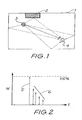
- Fig. 1 illustrates a room 1 in a typical office environment which includes items of furniture 2 and a transmitter 3 and receiver 4.
- a multipath mode of transmission from the transmitter 3 to the receiver 4 occurs. Reflections from the walls (and floor and ceiling) of the room 1 , items of furniture 2, and the like, within the room 1 cause the multiple path transmissions.
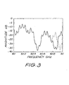
- the effect of the multiple path transmissions is that the receiver 4 receives an undelayed signal 5 which has travelled directly from the transmitter 3 to the receiver 4, and a number of delayed signals 6 which are received at a time after receipt of the undelayed signal 5.
- the magnitude of the delayed signals 6 is usually somewhat attenuated. Under some conditions, the magnitude of the undelayed signal 5 can be attenuated also, sometimes by more than some delayed signals 6.
- the delay time it is necessary for the length of time during which a single symbol is transmitted (the symbol period) to be substantially longer than the delay time in order that the received echoes of a first symbol do not mask the receipt of a subsequent symbol.
- This requirement has provided a severe upper limit to the rate at which data can be transmitted in such an environment.
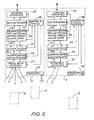
- Fig. 3 illustrates a typical channel characteristic over a short time period illustrating the magnitude of the received signal as a function of frequency in the 1 GHz band between 60 and 61 GHz. It will be seen that the received amplitude is by no means constant and, in particular, at various frequencies fading occurs. Furthermore, as indicated by dotted lines in Fig. 3 , the frequency at which fading occurs varies as a function of time because of movements within the room. Such a communication channel is called a time varying frequency selective fading channel.
- the change in the transmission characteristic indicated by dotted lines in Fig. 3 can, for example, be caused by the simple act of someone opening a briefcase positioned on a desk.
- the raised lid of the briefcase results in a change in the characteristic.
- Similar extremely short term changes can be caused by the receiver 4 itself moving, or other objects moving such as doors opening, people moving, and the like.
- the transmitter 3 can also move. The foregoing establishes a very hostile environment within which the desired radio transmissions are to take place. In particular, there is no preferred channel or even a guaranteed channel within the 1 GHz band.
- Fig. 4 illustrates in schematic form the general layout of a wireless LAN in accordance with a preferred embodiment of the present invention.
- a plurality of hubs 8 and mobile transceivers 9 are provided.
- the hubs 8 are interconnected by means of a backbone 10 which can take the form of either electrical conductors or optical fibre cable. As indicated by a dotted line in Fig. 4 the backbone 10 can constitute a loop. If desired, the backbone 10 can be connected to other computers 7 and, if desired, via a gateway 11 to the public switched telephone network 12.
- each office or each office in each building of acampus
- Either the backbone 10 can extend over the entire area to be covered, or the area can be covered by the use of multiple gateways and multiple backbones.
- the effective range of the transceiver within the hub 8 is arranged to essentially cover only that room.
- the limited transmission range for the hub 8 creates a corresponding cell 13 as indicated by broken lines in Fig. 4 .
- the length of the room can require that the room be provided with two hubs 8 in which case two partially overlapping cells 13 would be present within the one room.
- a number of component blocks are provided. These take the form of a network interface 20, a buffer memory 21, a framing, forward error correction (FEC) and modulating section 22, a framing, forward error correction and demodulation section 23, an IF (intermediate frequency) system section 24, a mm-wave receiver 25, a mm-wave transmitter 26, and an antenna 27 which is sufficiently broad in its radiation pattern to illuminate the entire cell.
- the antenna 27 can achieve this result statically or dynamically (with electronic or mechanical beam steering). All these items are connected to, and are operable by, a control and timing section 28. In addition, all are powered by an AC mains operable power supply 29.
- the mobile transceiver 9 has a battery powered power supply 39. This is possible because of the use of low power gallium arsenide devices in the receiver 35 and transmitter 36, in particular.
- the antenna 37 is preferably a steerable antenna which is electronically steerable by the control and timing section 38 so as to at least partially direct the transmissions to and from the mobile transceivers 9 towards the corresponding hub 8.
- This antenna improves the signal to noise ratio on the wireless link and attenuates delayed signals thereby improving multipath performance.
- FIG. 6 A more detailed block diagram of a portion of the transceiver 9 is illustrated in Figs. 6-9 .
- Fig. 6 the general arrangement of the transceiver 9 (excepting the terminal interface 30 and buffer memory 31) is illustrated.
- An intermediate stage of detail is given for the receiver 35 and transmitter 36, the receive intermediate frequency system 34 and receive demodulator 33 and the transmit intermediate frequency system 34 and transmit modulator 32.
- Full details of the modulation are given in Fig. 7 and of the demodulation in Fig. 8 .
- Fig. 7 the transmit path framing, FEC and modulating section 32 of Figs. 5 and 6 , is illustrated in detail.
- a binary data stream is applied to a CRC (cyclic redundancy check) Generate and Append block 40.
- the output of this block 40 or that of an End of Packet Pattern Generator 41 is selectively input to a rate 1/2 TCM (trellis coded modulation) Encoder 42.
- the output of encoder 42 is in turn input to a Di-bit Interleaver 43, the output of which is in turn input to a QPSK Encoder 44 which carries out differential encoding on a frame-by-frame basis.
- QPSK Encoder 44 and a synchronising header generator 45 are combined in frame assembly and zero pad insertion block 46 so that the frames are assembled and four zero pads inserted so that six carriers are generated to each side of, but not coincident with, the centre frequency.
- the assembled frames are then passed through an Inverse Fast Fourier Transform device 47 which uses a 16 point complex IFFT.
- the resultant signal is passed through Frame Serializer and Cyclic Extender block 48 to correctly sequence with 4 point cyclic extension the serial frames.
- the result is then passed via digital to analogue converters 49,50 to the intermediate frequency stage 34 of Figs. 5 and 6 .
- Fig. 8 In the receive path in the Framing, FEC and Demodulating section 33 of Figs. 5 and 6 , essentially the reverse procedures are carried out as illustrated in detail in Fig. 8 .
- the received signal from the intermediate frequency stage 34 is passed through the analogue to digital converters 60,61 and thence to the cyclic extractor and frame assembler 62.
- the resultant signal is passed through the Fast Fourier Transform device 63 to provide the essentially decoded signal.
- This signal is then simultaneously passed to a frame dis-assembler and zero pad remover 64 and to a synchronising calculator and detector 65 which provides start of message, end of message and symbol timing signals. These are passed to the control and timing unit 38 of Figs. 5 and 6 .
- the output of the frame dis-assembler and zero pad remover 64 is passed to a demodulator/detector 66 which carries out the necessary soft decision frame-by-frame differential demodulation and detection.
- the resulting output is passed to de-interleaver 67 and then to TCM decoder which is again a soft decision decoder.
- the decoder output is passed both to the buffer memory 31 of Fig. 5 and to CRC Accumulator and Checker 69. This latter device produces an error signal for the control and timing unit 38 of Figs. 5 and 6 if the demodulating/decoding has not correctly recovered the transmission data.
- a schematically indicated bi-directional amplifier 71 leads via a filter 72 to an image rejection mixer 73.
- the bi-directional amplifier 71 can be realised by use of a separate transmit amplifier and a separate receive amplifier as illustrated connected between the antenna 37 and filter 72 by appropriate switches under the control of the control and timing unit 38 of Figs. 5 and 6 .
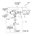
- the image rejection mixer 73 receives a 58GHz signal from a local oscillator (LO) unit 74.
- the first local oscillator (LO) is at a frequency of 58 GHz, resulting in an intermediate frequency band of 2-3 GHz.
- this signal is obtained by doubling the output signal of a 29 GHz oscillator. It is also preferable to perform some form of frequency stabilization on this oscillator, either by using an external frequency discriminator as illustrated in Fig. 9 , a stable internal resonator or some form of frequency/phase locked-loop.
- the image rejection mixer 73 is connected to both the receive I F system 34 and the transmit IF system 34 and can be shared between them by the use of an appropriate switch again under the control of the control and timing unit 38 of Figs. 5 and 6 .
- the use of the filter 72 provides additional rejection of the image frequency.
- the preferred form of modulation includes not only encoding but also fast fourier transforming, and its inverse.
- the transceiver 35,36 is preferably realised by means of one or more monolithic integrated circuits.
- the control and timing section 38 can power down each mobile transceiver 9 except when it is transmitting or receiving. This is determined by a polling scheme initiated by the hub transceivers 8.
- the hub 8 can communicate with each mobile transceiver 9 in turn inquiring if any data is required to be transmitted or access to other parts of the LAN is required.
- This polling of the various stations can comprise one of a number of standard techniques such as time division multiple access, ALOHA or slotted ALOHA, timed token passing, grant request schemes or other applicable techniques.
- the transmissions from the various transceivers 8 and 9 which comprise the network need not necessarily be at the same bit rate since some portions of the network need only a low speed of transmission (eg. printers) while others require a very high speed of transmission.
- This embodiment enables a variety of rates of transmission to be accommodated in a compatible network. This enables lower cost and/or low power consumption transceivers 9 to be used for printers or low data rate computing devices.
- the first technique is to transmit over a relatively large number of parallel sub-channels within the available bandwidth so that each channel has a low bit rate but the total, or overall bit rate, is high. This spread, by increasing the symbol length, overcomes the problem of delay time' and hence decreases the problems caused by inter-symbol interference.
- the second technique involves the transmission of the data in small packets having some form of data reliability monitoring and/or enhancement such as Forward Error Correction (FEC).
- FEC Forward Error Correction
- the length of the packet depends upon the method of data reliability enhancement and the hostility of the environment. Sufficiently small packets overcome the problem of the rapid time change of the channel characteristics.
- the third technique is interleaving (to be described hereafter) which is essentially a further data reliability enhancement. This technique improves the performance of many FEC schemes in overcoming the problems caused by nulls in the channel's frequency response.
- the first technique use of only ensemble modulation (the first technique) can be sufficient to produce an adequate result.
- the second technique should be employed in combination with the first technique.
- the initial form of the second technique is data reliability enhancement by automatic repeat request (ARQ).
- ARQ automatic repeat request
- the maximum permissible packet length able to be chosen is that which will ensure a practical probability of errorfree transmission.
- FEC forward error correction
- data redundancy and/or permutation modulation should be also used. If necessary, both channel sounding and redundancy technique(s) can be used.
- typical time delays due to multipath transmission are of the order of 50 ns because of the dimensions of typical rooms.
- a desired bit rate of the order of 100 Mbit/s this indicates that the bit period is 10 ns which is only 20% of the delay time.
- each channel must have a bit rate of approximately 8.3 Mbit/s.
- 12 bits are encoded and sent as a symbol, then the symbol time is of the order of 120 ns which is greater than the delay time.
- the choice of the optimium number of sub-channels depends on the environment.
- the first is redundancy sufficient for the detection of errors so that there may be subsequent re-transmission of at least selected data in which those passages of information not correctly received are re-sent.
- the re-transmission is not necessarily over the same sub-channel or channel.
- the second is forward error correction which has a redundancy sufficient for non-interactive correction.
- a third is permutation modulation such as multi-tone amplitude shift keying which has built-in redundancy. Any of these techniques allow the demodulator to correct for a relatively small percentage of errors in the received bits.
- the preferred type of modulation in each sub-channel is multi-level modulation of carrier amplitude and/or phase (mQAM).
- the modulation family mQAM includes amplitude shift keying (ASK), multi-level ASK (mASK), permutation modulation, binary phase shift keying (BPSK), multi-level phase shift keying (mPSK), amplitude phase keying (APK), multi-level APK (mAPK) and the like.
- Transceivers 9 for devices such as printers which require a lower bit rate transmission can use the techniques which give a lower spectral efficiency such as amplitude shift keying (ASK).
- ASK amplitude shift keying
- a variant of ASK over an ensemble of carriers is called permutation modulation.
- the transmission is m-ary where a transmitted symbol can encode log 2 m binary digits.
- Each symbol transmitted has a built in redundancy so that if several of the symbols are received in error due to the poor nature of the corresponding part of the channel, a correct decision can still be made as to which of the allowed symbols was transmitted.
- a choice of the symbols with the appropriate orthogonality can be made using a number of well known information theory techniques or by a computer search for the appropriate codes. Due to the high redundancy and limited bandwidth efficiency of permutation modulation, this system does not yield a high spectral efficiency (expressed as bits/Hz). For the system of the illustrated embodiment this can be lower than 0.25 bit/Hz. It is, however, relatively simple to implement and so is desirably used in a lower cost, lower bit rate transceiver 9 for printers, for example, which are compatible with the higher performance embodiments described below.
- phase shift keying PSK
- BPSK binary phase shift keying
- QPSK quadrature phase shift keying
- the incoming binary data stream at a bit rate "b” is encoded using a conventional forward error correction scheme such as, but not restricted to Reed-Solomon or convolutional coding.
- a conventional forward error correction scheme such as, but not restricted to Reed-Solomon or convolutional coding.
- Such coding increases the number of bits to be transmitted by a factor "r” which is the reciprocal of the code rate.
- the encoded stream, at a bit rate b.r is then split into "p" parallel paths, and each path used to BPSK modulate a separate carrier in the ensemble, giving an effective symbol duration, on the radio link, of p/(b.r.) seconds.
- the resulting signal is then transmitted over the channel and received by the other unit with some sub-channels error free and others with a potentially substantial error rate, due to the frequency selective nature of the channel.
- the received carriers are demodulated and the individual bit streams combined (or aggregated) to form an encoded data stream with possible errors (mainly from the bad sub-channels) which is then decoded by a device (such as a Reed-Solomon or Viterbi decoder). Any errors in the received signal are normally completely corrected by this decoding process.
- a device such as a Reed-Solomon or Viterbi decoder. Any errors in the received signal are normally completely corrected by this decoding process.
- a weighting can be given as to the confidence of the accuracy of the output of each BPSK demodulator based upon the amplitude of the received carrier. This weighting can be used as an additional input to the decoding device to determine which bits are more likely to be in error and to increase the performance of this device in correcting as many errors as possible in the transmission.
- TCM trellis-coded-modulation
- link data interleaving schemes can be used, in this system, to further improve the error correcting performance of FEC codes which distribute the contribution of individual data elements over fewer carriers than the total number in the ensemble.
- Link data interleaving schemes do this by distributing the encoded data between the carriers in such a way that the correlation in error probability of those carriers associated with any given element of uncoded input data is minimised. On average, this corresponds to maximising the minimum frequency spacing between those carriers.
- a suitable interleaving scheme is -
- Such an interleaving scheme is typically implemented by means of demultiplexers, shift registers and multiplexers in substantially conventional fashion.
- an additional error correction layer such as cyclic redundancy checked (CRC) automatic repeat request (ARQ),can be used.
- CRC cyclic redundancy checked
- ARQ automatic repeat request
- This error correction layer requests the re-transmission of those symbols which are believed to be in error. This re-transmission can occur over the same frequency channel, or a request can be made to the control and timing section to shift the entire frequency channel by some predetermined amount, or to change antenna characteristics such as polarisation, to increase the probability of error free transmission.
- the transmitted data is divided into packets of short duration (typically 100 microseconds). During this short time period it is satisfactory to assume that the transmission characteristics are essentially stationary.
- a channel selection technique is to channel sound priorto transmission of the packet. If necessary, this allows the data rate to be reduced if a particularsub-channel or channel is found to be degraded.
- the preferred method of generating and demodulating multi-carrier modulation schemes uses a device capable of performing Fast Fourier Transforms (FFTs) and Inverse Fast Fourier Transforms (IFFTs) on complex data at high speeds.
- FFTs Fast Fourier Transforms
- IFFTs Inverse Fast Fourier Transforms
- Such a device is described in Australian Patent No. 610,934 entitled “A Transform Processing Circuit” granted to the present applicants.
- 16 point fast Fourier transformation is used.
- Cyclic extension is a technique for enhancing the multi-path tolerance of FFT-based ensemble modulation schemes by reducing the degradation of sub-channel orthogonality produced by channel delay spread effects and demodulator timing errors. It consists, at the modulator, of extending the time duration of individual multicarrier symbols by appending, to the FFT output frame, a copy of that frame, then truncating the combination to the desired length.
- the length of the extension is a compromise between tolerance to multipath induced intra-symbol interference and the reduction of channel spectral efficiency. It preferably corresponds to the time interval over which the channel impulse response has substantial energy.
- an essentially uncorrupted multicarrier symbol is excised (by cyclic extraction) from the potentially distorted incoming extended symbol, whose ends may be corrupted by the extended impulse response of a multipath channel.
- This excised symbol is then used in the FFT based demodulation process. For example, when using a 16 point FFT, a cyclic extension length of 4 points can be used.
- A-related (but more computationally intensive) process is that of "tapering” or “windowing”, whereby the amplitude of the multicarrier symbol is varied over part of the symbol time in order to reduce the mutual cross-talk of sub-channels more than a few carrier spacings apart in frequency.
- the analogue (reconstruction/ anti-aliasing) filter selectivity requirements for given adjacent channel suppression/rejection, can be relaxed by using a larger transform whose higher frequency bins are zero-filled in the modulator and ignored in the demodulator. This corresponds to not generating the higher frequency (out-of-band) carriers at the transmitter and ignoring any received energy at those frequencies, so the FFT provides (subject to dynamic range considerations) a significant part of the band edge selectivity.
- Zero insertion can also be used to remove the band-centre carrier (DC at baseband) to reduce susceptibility to DC offset drifts in the system. For example, when using a 16 point FFT device 63 only 12 carriers are preferably used.
- a device 65 is required to synchronize the receiver to the incoming data. This device can, for example, compare this incoming data to the receiver's timing signals, calculate the difference in sumbol and bit times and pass this information to the control and timing unit which would then perform the appropriate corrections to achieve synchronization or zero difference.
- a preferred synchronisation scheme having multipath tolerance commensurate with ensemble modulation and sharing of the FFT hardware, determines multicarrier symbol timing and gross local oscillator frequency difference by measurement of the relative phases of several carriers present in the message header generated by generator 45 and comparision of these with the known phase relationship of the transmitted carriers at the beginning of the header transmission.
- the IF systems 34 are shown in Fig. 6 and consists of an I,Q up converter for the transmitter and I,Q down converter for the receiver.
- the second LO units of the IF systems 34 are tuned over the band 2-3 GHz and this allows the conversion of the signals to and from baseband.
- interleaving and bit reversal of the transmitted data to decrease the received error rate can be accomplished by utilizing the bit reversal inherent in the FFT conversion.
- the antenna 37 can utilize polarisation diversity to improve reception.
- One arrangement for the simultaneous operation of low bit rate transceivers and high bit rate transceivers is to allocate, say, half the available (high bit) channel to the low bit rate transceivers.
- the low bit rate transceivers utilize only half of the available bandwidth and a hub can transmit data at the low rate to two low bit rate transceivers at the same time.
- the same hub hardware is used for both high bit and low bit rate transmissions.
- the LAN need not incorporate hubs 8 since the mobile transceivers 9 can transmit to, and from, each other directly within the predetermined cell range.
- a LAN is termed a peer-to-peer LAN.
- the hubs 8 although described as being interconnected by electric cable and/or optical fibre, can also be inter-connected by a radio or infra-red link.
- the link can form a part of the backbone 10 or constitute the inter-hub communication link.
Landscapes
- Engineering & Computer Science (AREA)
- Signal Processing (AREA)
- Computer Networks & Wireless Communication (AREA)
- Mobile Radio Communication Systems (AREA)
- Small-Scale Networks (AREA)
- Radar Systems Or Details Thereof (AREA)
- Transceivers (AREA)
Claims (56)
- Sender-Empfänger zum Betrieb in einer beschränkten Mehrwegübertragungsumgebung, die gegenüber frequenzselektivem Schwund und Symbolinterferenz empfindlich ist, wobei der Sender-Empfänger umfasst:eine Hochfrequenzeinrichtung (34, 35, 36, 37) umfassend eine Antenne (37) zum Übertragen und Empfangen von Hochfrequenzsignalen;eine Übertragungssignalverarbeitungseinrichtung (32) zum Empfangen von Eingabedaten von einem Eingabedatenkanal (31) und zum Verarbeiten der Eingabedaten zur Übertragung durch die Hochfrequenzeinrichtungen (34, 35, 36, 37), wobei die Übertragungssignalverarbeitungseinrichtung (32) eine Modulationseinrichtung zur Modulation der Eingabedaten umfasst, undeine Empfangssignalverarbeitungseinrichtung (33) zum Verarbeiten von durch die Hochfrequenzeinrichtung (34, 35, 36, 37) empfangenen Signalen und zum Ausgeben von Daten an einen Ausgabedatenkanal (31);dadurch gekennzeichnet,dass die Modulationseinrichtung (44, 46, 47) betriebsfähig ist, um die Eingabedaten in eine Mehrzahl von Subkanälen verschiedener Frequenz zu modulieren, wobei jeder Subkanal eine Sequenz von Datensym bolen trägt, so dass die Periode eines Subkanalsymbols länger ist als eine vorherbestimmte, für den Zeitverzug der bedeutenden der nicht-direkten Übertragungswege repräsentative Periode;dass die genannte Übertragungssignalverarbeitungseinrichtung (33) ferner eine Einrichtung (42) umfasst, die die Datenzuverlässigkeit der Eingabedaten, die an die Modulationseinrichtung (44, 46, 47) weitergegeben werden, steigert, wobei die Einrichtung (42) zum Steigern der Datenzuverlässigkeit betriebsfähig ist, um Vorwärts-Fehlerkorrektur auszuführen; unddass die Übertragungssignalvearbeitungseinrichtung (33) ferner eine zwischen der genannten Eingabedatenzuverlässigkeitssteigerungseinrichtung (42) und der genannten Modulationseinrichtung (44, 46, 47) zwischengestellte Einrichtung (43) umfasst, um Blöcke dieser genannten Daten zu verschachteln;wobei die genannte Einrichtung (43) zum Verschachteln betriebsfähig ist um Daten für einen Rahmen zu verschachteln, undwobei der Ausgang der Verschachtelungseinrichtung der Modulationseinrichtung zur Verfügung gestellt wird zur Übertragung des genannten Rahmens, wobei die verschachtelten Daten gleichzeitig übertragen werden unter Verwendung der genannten Mehrzahl von Subkanälen.
- Sender-Empfänger gemäß Anspruch 1, dadurch gekennzeichnet, dass die genannten Blöcke der genannten Daten Bits sind.
- Sender/Empfänger gemäß Anspruch 1 oder Anspruch 2, wobei die Übertragungssignalverarbeitungseinrichtung betriebsfähig ist, um zur Übertragung serielle Rahmen in ein Paket zu vearbeiten, das eine Dauer aufweist, die geringer oder gleich einer Zeitdauer ist, über die eine Übertragungseigenschaft der genannten Übertragungsumgebung im Wesentlichen gleichbleibend ist.
- Sender/Empfänger gemäß Anspruch 1 oder Anspruch 2, wobei die genannte Übertragungssignalverarbeitungseinrichtung betriebsfähig ist, um zur Übertragung serielle Rahmen in ein Paket zu verarbeiten, das eine Dauer von 100 Mikrosekunden hat.
- Sender/Empfänger gemäß einer der vorhergehenden Ansprüche, dadurch gekennzeichnet, dass die genannte Einrichtung (42) zum Steigern der Datenzuverlässigkeit betriebsfähig ist, um eine Kodierung mit einem Faltungscode durchzuführen.
- Sender-Empfänger gemäß einem der vorhergehenden Ansprüche, dadurch gekennzeichnet, dass die Modulationseinrichtung (44, 46, 47) eine zyklische Erweiterungseinrichtung (48) umfasst, die ausgebildet ist, die Dauer der Subkanalsymbole auszudehnen.
- Sender-Empfänger gemäß einem der vorhergehenden Ansprüche, dadurch gekennzeichnet, dass die Modulationseinrichtung (44, 46, 47) dazu vorgesehen ist, eine Modulation zu verwenden ausgewählt aus der Modulationsfamilie bestehend aus: Mehrebenenamplitudenphasenumtastung (mASK), Permutationsmodulation, Binärphasenumtastung (BPSK), Mehrebenenphasenumtastung (mPSK) und Mehrebenenamplitudenphasentastung (mAPK).
- Sender/Empfänger gemäß einem der vorhergehenden Ansprüche, wobei die Übertragungssignalvearbeitungseinrichtung weiterhin einen Rahmenassemblierer (46) zum Assemblieren von Datenblöcken in einem genannten Rahmen mit Nullenauffüllung umfasst.
- Sender/Empfänger gemäß Anspruch 8, wobei die Übertragungssignalverarbeitungseinrichtung weiterhin einen Synchronisierungskopferzeuger (45) umfasst, um dem Rahmenassemblierer (46) einen Kopf zur Verfügung zu stellen.
- Sender-Empfänger gemäß einem der vorhergehenden Ansprüche, dadurch gekennzeichnet, dass die Empfangssignalverarbeitungseinrichtung (33) eine Demodulationseinrichtung (63, 64, 66) umfasst zum Demodulieren empfangener Symbole der Mehrzahl an Subkanälen in Ausgabedaten für den Ausgabedatenkanal (31).
- Sender-Empfänger gemäß Anspruch 6 und 10, dadurch gekennzeichnet, dass die Demodulationseinrichtung (63, 64, 66) eine zyklische Extraktionseinrichtung (62) umfasst, die dazu ausgebildet ist, die Subkanalsymbole aus den Subkanalsymoblen ausgedehnter Dauer herauszuholen.
- Sender-Empfänger gemäß einem der vorhergehenden Ansprüche, dadurch gekennzeichnet, dass der Sender-Empfänger ferner umfasst:eine Synchronisationseinrichtung (65) zum Synchronisieren der Hochfrequenzeinrichtung (34, 35, 36, 37) und der Empfangssignalverarbeitungseinrichtung (33) mit ankommenden Signalen; undeine zweite Oszillatoreinrichtung (90), um die Konvertierung der empfangenen Signale zu und aus einer Grundbandfrequenz zu ermöglichen, wobei die Betriebsfrequenz der zweiten Oszillatoreinrichtung (90) gesteuert werden kann.
- Sender-Empfänger gemäß Anspruch 12, dadurch gekennzeichnet, dass die Synchronisationseinrichtung (65) betriebsfähig ist, um einen Kanalsymbolzeitwert und eine Differenz zwischen der Betriebsfrequenz des Sender-Empfängers und einer Betriebsfrequenz eines zweiten Sender-Empfängers (8) zu bestimmen.
- Sender-Empfänger gemäß Anspruch 13, dadurch gekennzeichnet, dass die Synchronisationseinrichtung (65) dazu ausgebildet ist, die genannte Kanalsymbolzeit und die genannte Differenz durch Messung der relativen Phasen von wenigsten einem Paar von Subkanalträgern verschiedener Frequenz zu bestimmen und zum Vergleichen der gemessenen Phasendifferenzen mit einem vorherbestimmten Phasenverhältnis der übertragenen Subkanalträger am Anfang der Übertragung.
- Sender/Empfänger gemäß einem der vorhergehenden Ansprüche, dadurch gekennzeichnet, dass die genannte Modulationseinrichtung einen auf einer komplexen schnellen Fouriertransformation beruhenden Modulierer umfasst, der ausgebildet ist, eine inverse schnelle Fouriertransformation auf Daten zur gleichzeitigen Übertragung durchzuführen.
- Sender/Empfänger gemäß Anspruch 15, wobei die genannte Empfangssignalverarbeitungseinrichtung umfasst:einen FFT-Schaltkreis zur Demodulation der empfangenen Datensymbole in empfangene Daten;einen Entschachtelungs-Schaltkreis zum Entschachteln der empfangenen Daten in einen Datenstrom; undeinen Dekodierer-Schaltkreis zur Erzeugung von Ausgangsdaten aus dem genannten Datenstrom, um diese dem genannten Ausgangsdatenkanal zur Verfügung zu stellen.
- Sender/Empfänger gemäß Anspruch 9, wobei die Empfangssignalverarbeitungseinrichtung eine Synchronisierungserfassungseinrichtung zur Erfassung eines Kopfes in den empfangen Daten umfasst.
- Sender-Empfänger gemäß einem der vorhergehenden Ansprüche, ferner umfassend eine Schalteinrichtung (35, 36) zum wahlweisen Koppeln der Antenneneinrichtung (37) an die Übertragungssignalverarbeitungseinrichtung (32) zur Datenübertragung und an die Signalverarbeitungseinrichtung (33) zum Datenempfang.
- Sender-Empfänger gemäß einem der vorhergehenden Ansprüche, wobei die genannte Antenneneinrichtung Polarisationsdiversität zur Verfügung stellt.
- Sender-Empfänger gemäß einem der vorhergehenden Ansprüche, dadurch gekennzeichnet, dass der Sender-Empfänger (9) betriebsfähig ist, um Daten mit Hochfrequenzen über 10 GHz zu übertragen und zu empfangen.
- Drahtloses LAN umfassend:eine Mehrzahl von Hub-Sender-Empfängern (8), die aneinander gekoppelt sind, um eine Mehrzahl an Datenquellen und -zielen zu bilden;undeine Mehrzahl an mobilen Sender-Empfängern, wobei jeder mobile Sender-Empfänger einen Sender-Empfänger (9) gemäß einem der vorhergehenden Ansprüche umfasst, wobei jeder mobile Sender-Empfänger (9) an eine Datenverarbeitungseinrichtung gekoppelt ist, wobei zwischen jeder der genannten Datenverarbeitungseinrichtungen und einem entsprechenden der genannten Sender-Empfänger (9) Daten fließen, um übertragen oder empfangen zu werden, wobei jeder der genannten Sender-Empfänger (9) zum Daten-Sende-Empfangs-Betrieb durch Funkübertragungen an einen der genannten Hub-Empfänger (8) in einer beschränkten Mehrwegumgebung ausgebildet ist.
- Drahtloses Peer-to-Peer LAN umfassend:eine Mehrzahl mobiler Sender-Empfänger, wobei jeder mobile Sender-Empfänger einen Sender-Empfänger (9) gemäß einem der Ansprüche 1 bis 20 umfasst und zum Daten-Empfangs-Betrieb durch Funkübertragungen zwischen jenen in einer beschränkten Mehrwegumgebung ausgebildet ist, wobei jeder der genannten Sender-Empfänger (9) an eine Datenverarbeitungseinrichtung gekoppelt ist, wobei zwischen der Datenverarbeitungseinrichtung und einem entsprechenden Sender-Empfänger (9) Daten fließen um übertragen oder empfangen zu werden.
- Sender zum Betrieb in einer beschränkten Mehrwegübertragungsumgebung, die gegenüber frequenzselektivem Schwund und zwischen Symbolinterferenz empfindlich ist, wobei der Sender umfasst:eine Hochfrequenzeinrichtung (34, 35, 36, 37) umfassend eine Antenne (37) zum Übertragen von Hochfrequenzsignalen undeine Übertragungssignalverarbeitungseinrichtung (32) zum Empfangen von Eingabedaten von einem Eingabedatenkanal (31) und zum Verarbeiten der Eingabedaten zur Übertragung durch die Hochfrequenzeinrichtung (34, 35, 36, 37), wobei die Übertragungssignalverarbeitungseinrichtungen (32) eine Modulationseinrichtung (44, 46, 47) zum Modulieren der Eingabedaten umfasst;dadurch gekennzeichnet,dass die Modulationseinrichtung (44, 46, 47) betriebsfähig ist, um die Eingabedaten in eine Mehrzahl von Subkanälen verschiedener Frequenz zu modulieren, wobei jeder Subkanal eine Sequenz von Datensymbolen trägt, derart, dass die Periode eines Subkanalsymboles länger ist als eine vorherbestimmte, für den Zeitverzug der bedeutenden der nicht-direkten Übertragungswege repräsentative Periode;dass die Übertragungssignalvearbeitungseinrichtung (32) ferner eine Einrichtung (42) umfasst, die die Datenzuverlässigkeit der Eingabedaten, die an die Modulationseinrichtung (44, 46, 47) weitergegeben werden, steigern, wobei die genannte Einrichtung zur Steigerung der Datenzuverlässigkeit betriebsfähig ist, um eine Vorwärts-Fehlerkorrektur durchzuführen; unddass die Übertragungssignalverarbeitungseinrichtung (32) ferner eine zwischen der Eingabedatenzuverlässigkeitssteigerungseinrichtungen (42) und der Modulationseinrichtung (44, 46,47) zwischengestellte Einrichtung (43) umfasst, um Blöcke der genannten Daten zu verschachteln, wobei die genannte Einrichtung (43) zur Verschachtelung betriebsfähig ist, um Daten für einen Rahmen zu verschachteln, und wobei der Ausgang der Verschachtelungseinrichtung der genannten Modulationseinrichtung zur Verfügung gestellt wird zur Übertragung des genannten Rahmens, wobei die verschachtelten Daten zeitgleich übertragen werden unter Verwendung der genannten Mehrzahl von Subkanälen.
- Sender gemäß Anspruch 23, dadurch gekennzeichnet, dass die Datenblöcke Bits sind.
- Sender gemäß Anspruch 23 oder 24, wobei die genannte Übertragungssignalverarbeitungseinrichtung betriebsfähig ist, zur Übertragung serielle Rahmen in ein Paket zu verarbeiten, das eine Dauer aufweist, die geringer als oder gleich einer Zeitdauer ist, über die eine Übertragungseigenschaft der genannten Übertragungsumgebung im Wesentlichen gleichbleibend ist.
- Sender gemäß Anspruch 23 oder 24, wobei die genannte Übertragungssignalverarbeitungseinrichtung betriebsfähig ist, zur Übertragung serielle Rahmen in ein Paket zu verarbeiten, das eine Dauer von 100 Mikrosekunden hat.
- Sender gemäß einem der Ansprüche 23 bis 26, dadurch gekennzeichnet, dass die Einrichtung (42) zum Steigern der Datenzuverlässigkeit betriebsfähig ist, eine Kodierung mit einem Faltungscode auszuführen.
- Sender gemäß einem der Ansprüche 23 bis 27, dadurch gekennzeichnet, dass die Modulationseinrichtung (44, 46, 47) eine zyklische Erweiterungseinrichtung (48) umfasst, die ausgebildet ist, um die Dauer der Subkanalsymbole auszuweiten.
- Sender gemäß einem der Ansprüche 23 bis 28, dadurch gekennzeichnet, dass die Modulationseinrichtung (44, 46, 47) dazu ausgebildet ist, eine Modulation zu verwenden, die ausgewählt ist aus der Modulationsfamilie bestehend aus: Mehrebenenamplitudenphasentastung (mASK), Permuationsmodulation, Binärphasenumtastung (BPSK), Mehrebenenphasenumtastung (mPSK) und Mehrebenenamplitudenphasentastung (mAPK).
- Sender gemäß einem der Ansprüche 23 bis 29, wobei die Übertragungssignalverarbeitungseinrichtung weiterhin einen Rahmenassemblierer (46) umfasst zur Assemblierung von Datenblöcken in einen genannten Rahmen zusammen mit Nullenauffüllung.
- Sender gemäß Anspruch 30, wobei die Übertragungssignalverarbeitungseinrichtung weiterhin einen Synchronisierungskopferzeuger (45) umfasst um dem Rahmenassemblierer (46) einen Kopf zur Verfügung zu stellen.
- Sender gemäß einem der Ansprüche 23 bis 31, dadurch gekennzeichnet, dass der Sender ferner umfasst:eine Synchronisationseinrichtung (65) zum Synchronisieren der Hochfrequenzeinrichtung (34, 35, 36, 37) und der Empfangssignalverarbeitungseinrichtung (33) mit ankommenden Signalen; undeine zweite Oszillatoreinrichtung (90), um die Konvertierung der empfangen Signale zu und aus einer Grundbandfrequenz zu ermöglichen,wobei die Betriebsfrequenz der zweiten Oszillatoreinrichtung (90) gesteuert werden kann.
- Sender gemäß Anspruch 32, dadurch gekennzeichnet, dass die Synchronisationseinrichtung (65) betriebsfähig ist, um einen Kanalsymbolzeitwert und eine Differenz zwischen der Betriebsfrequenz des genannten Senders und einer Betriebsfrequenz eines zweiten Senders (8) zu bestimmen.
- Sender gemäß Anspruch 33, dadurch gekennzeichnet, dass die Synchronisationseinrichtung (65) dazu ausgebilet ist, die genannte Kanalsymbolzeit und die genannte Differenz durch Messung der relativen Phasen von wenigsten einem Paar von Subkanalträgern verschiedener Frequenz zu bestimmen und zum Vergleichen der gemessenen Phasendifferenzen mit einem vorherbestimmten Phasenverhältnis der übertragenen Subkanalträger am Anfang der Übertragung.
- Sender gemäß einem der Ansprüche 23 bis 34, dadurch gekennzeichnet, dass die genannte Modulationseinrichtung einen auf einer komplexen schnellen Fouriertransformation beruhenden Modulierer umfasst, der ausgebildet ist, um eine inverse schnelle Fouriertransformation auf Daten zur gleichzeitigen Übertragung durchzuführen.
- Sender gemäß einem der Ansprüche 23 bis 35, wobei die genannte Antenneneinrichtung Polarisationsdiversität zur Verfügung stellt.
- Sender gemäß einem der Ansprüche 23 bis 36, dadurch gekennzeichnet, dass der Sender betriebsfähig ist, um Daten mit Hochfrequenz über 10 GHz zu übertragen.
- Verfahren zum Übertragen von Daten unter Verwendung von Hochfrequenzwellen in einer beschränkten Mehrwegübertragungsumgebung, die gegenüber frequenzselektivem Schwund und Zwischen-Symbolinterferenz empfindlich ist, wobei das Verfahren umfasst:Empfangen von Eingabedaten von einem Eingabedatenkanal (31);Modulation der Eingabedaten; undÜbertragen der modulierten Daten;dadurch gekennzeichnet,dass der Modulationsschritt die Eingabedaten in eine Mehrzahl von Subkanälen verschiedener Frequenz moduliert, wobei jeder Subkanal eine Sequenz von Datensymbolen trägt, derart, dass die Periode eines Subkanalsymboles länger ist als eine vorherbestimmte , für den Zeitverzug der bedeutenden der nicht-direkten Übertragungswege repräsentative Periode;wobei das Verfahren weiterhin die weiteren Schritte der Anwendung einer Vorwärts-Fehlerkorrektur auf die genannten Daten, um eine Steigerung der Datenzuverlässigkeit zur Verfügung zustellen und der Verschachtelung der Blöcke der genannten gesteigerten Daten,wobei der genannte Schritt der Verschachtelung von Blöcken die Verschachtelung von Daten für einen Rahmen umfasst, und wobei der genannte Modulisierungsschritt die Modulisierungjedes Rahmens zur gleichzeitigen Übertragung von verschachtelten Daten unter Verwendung der Mehrzahl von Subkanälen umfasst.
- Verfahren gemäß Anspruch 38, dadurch gekennzeichnet, dass die Datenblöcke Bits sind.
- Verfahren gemäß Anspruch 38 oder 39, weiterhin umfassend die Übertragung von seriellen Rahmen in einem Paket, das eine Dauer aufweist, die geringer als oder gleich einer Zeitdauer ist, über die eine Übertragungseigenschaft der genannten Übertragungsumgebung im wesentlichen gleichbleibend ist.
- Verfahren gemäß Anspruch 38 oder 39, weiterhin umfassend die Übertragung von seriellen Rahmen in einem Paket, das eine Dauer von 100 Mikrosekunden hat.
- Verfahren gemäß einem der Ansprüche 38 bis 41, dadurch gekennzeichnet, dass die Steigerung der Datenzuverlässigkeit eine konvolutionelle Kodierung ist.
- Verfahren gemäß einem der Ansprüche 38 bis 42, gekennzeichnet durch den weiteren Schritt des Ausdehnens der Dauer der genannten Subkanalsymbole.
- Verfahren gemäß einem der Ansprüche 38 bis 43, dadurch gekennzeichnet, dass die Modulation aus der Modulationsfamilie stammt, die besteht aus: Mehrebenenamplitudenumtastung (mASK), Permutationsmodulation, Binärphasenumtastung (BPSK), Mehrebenenphasenumtastung (mPSK) und Mehrebenenamplitudenphasentastung (mAPK).
- Verfahren gemäß einem der Ansprüche 38 bis 44, weiterhin umfassend einen Schritt der Assemblierung der verschachtelten Blöcke in einen genannten Rahmen gemeinsam mit Nullenauffüllung.
- Verfahren gemäß Anspruch 45, wobei der Assemblierungsschritt durch einen Rahmenassemblierer durchgeführt wird und das Verfahren weiterhin umfasst dem Rahmenassemblierer einen Synchronisierungkopf zur Verfügung zu stellen.
- Verfahren gemäß einem der Ansprüche 38 bis 46, gekennzeichnet durch den weiteren Schritt, dass die empfangenen Symbole der Mehrzahl an Subkanälen in Ausgabedaten für einen Ausgabedatenkanal (31) demoduliert werden.
- Verfahren gemäß Anspruch 47, gekennzeichnet durch den weiteren Schritt des Verkürzens der Dauer der Subkanalsymbole.
- Verfahren gemäß einem der Ansprüche 38 bis 48, gekennzeichnet durch die weiteren Schritte:Synchronisieren der Hochfrequenzeinrichtung (34, 35, 36, 37) und der Empfangssignalverarbeitungseinrichtung (33) mit ankommenden Signalen unter Verwendung einer Synchronisationseinrichtung (65); undKonvertieren der Empfangssignale zu und aus einer Grundbandfrequenz unter Verwendung einer zweiten Oszillatoreinrichtung (90), wobei die Betriebsfrequenz der zweiten Oszillatoreinrichtung (90) gesteuert werden kann.
- Verfahren gemäß Anspruch 49, dadurch gekennzeichnet, dass die Synchronisationseinrichtung (65) betriebsfähig ist, um einen Kanalsymbolzeitwert und eine Differenz zwischen der Betriebsfrequenz eines ersten Sender-Empfängers (9) und einer Betriebsfrequenz eines zweiten Sender-Empfängers (8) zu bestimmen.
- Verfahren gemäß Anspruch 50, dadurch gekennzeichnet, dass die Kanalsymbolzeit und die genannte Differenz durch Messung der relativen Phasen von wenigstens einem Paar von Subkanalträgern verschiedener Frequenz bestimmt werden und Vergleichen der gemessenen Phasendifferenzen mit einer vorbestimmten Phasenbeziehung der gesendeten Subkanalträger am Anfang der Übertragung.
- Verfahren gemäß einem der Ansprüche 38 bis 51, wobei der genannte Schritt des Modulierens von Daten die Ausführung einer inversen schnellen Fouriertransformation umfasst.
- Verfahren gemäß Anspruch 52, weiterhin umfassend die Erweiterung eines Ausgangsrahmens, der durch die genannte inverse schnelle Fouriertransformation erzeugt wird unter Verwendung eines zyklischen Erweiterers um eine zyklische Erweiterung hinzuzufügen.
- Verfahren gemäß einem der Ansprüche 38 bis 53, wobei die genannte Antenneneinheit Polarisationsdiversität zur Verfügung stellt.
- Verfahren gemäß einem der Ansprüche 38 bis 54, dadurch gekennzeichnet, dass der genannte Schritt der Übertragung bei Hochfrequenzen über 10 GHz ausgeführt wird.
- Verfahren gemäß einem der Ansprüche 38 bis 55, wobei die genannten Schritte stattfinden, um Daten kabellos in einem kabellosen lokalen Netzwerk zu übertragen.
Priority Applications (1)
| Application Number | Priority Date | Filing Date | Title |
|---|---|---|---|
| DE69330158T DE69330158T3 (de) | 1992-11-27 | 1993-11-24 | Gerät und Verfahren für drahtlose Kommunikation |
Applications Claiming Priority (3)
| Application Number | Priority Date | Filing Date | Title |
|---|---|---|---|
| AUPL606992 | 1992-11-27 | ||
| AUPL606992 | 1992-11-27 | ||
| AUPL6069/92 | 1992-11-27 |
Publications (4)
| Publication Number | Publication Date |
|---|---|
| EP0599632A2 EP0599632A2 (de) | 1994-06-01 |
| EP0599632A3 EP0599632A3 (de) | 1994-11-30 |
| EP0599632B1 EP0599632B1 (de) | 2001-04-18 |
| EP0599632B3 true EP0599632B3 (de) | 2012-11-14 |
Family
ID=3776560
Family Applications (1)
| Application Number | Title | Priority Date | Filing Date |
|---|---|---|---|
| EP93309371A Expired - Lifetime EP0599632B3 (de) | 1992-11-27 | 1993-11-24 | Gerät und Verfahren für drahtlose Kommunikation |
Country Status (10)
| Country | Link |
|---|---|
| US (1) | US5487069A (de) |
| EP (1) | EP0599632B3 (de) |
| JP (1) | JP3438918B2 (de) |
| AT (1) | ATE200720T1 (de) |
| AU (1) | AU666411B2 (de) |
| DE (1) | DE69330158T3 (de) |
| DK (1) | DK0599632T3 (de) |
| ES (1) | ES2156867T7 (de) |
| GR (1) | GR3036146T3 (de) |
| PT (1) | PT599632E (de) |
Cited By (1)
| Publication number | Priority date | Publication date | Assignee | Title |
|---|---|---|---|---|
| US8351321B2 (en) | 1995-02-06 | 2013-01-08 | Htc Corporation | Systems and method for orthogonal frequency divisional multiplexing |
Families Citing this family (142)
| Publication number | Priority date | Publication date | Assignee | Title |
|---|---|---|---|---|
| USRE37802E1 (en) | 1992-03-31 | 2002-07-23 | Wi-Lan Inc. | Multicode direct sequence spread spectrum |
| USRE39395E1 (en) | 1992-11-02 | 2006-11-14 | Negotiated Data Solutions Llc | Data communication network with transfer port, cascade port and/or frame synchronizing signal |
| USRE39116E1 (en) | 1992-11-02 | 2006-06-06 | Negotiated Data Solutions Llc | Network link detection and generation |
| EP0596648A1 (de) | 1992-11-02 | 1994-05-11 | National Semiconductor Corporation | Erkennung du Fähigkeiten eines Netzendpunkts |
| DE4329898A1 (de) * | 1993-09-04 | 1995-04-06 | Marcus Dr Besson | Kabelloses medizinisches Diagnose- und Überwachungsgerät |
| US5602669A (en) * | 1994-06-30 | 1997-02-11 | Sony Corporation | Digital signal transmission apparatus, digital signal transmission method, and digital signal transmitter-receiver |
| US6092117A (en) * | 1994-09-02 | 2000-07-18 | Packard Bell Nec | System and method for automatically reconnecting a wireless interface device to a host computer |
| US5719883A (en) * | 1994-09-21 | 1998-02-17 | Lucent Technologies Inc. | Adaptive ARQ/FEC technique for multitone transmission |
| US5764693A (en) * | 1994-11-14 | 1998-06-09 | Research In Motion Limited | Wireless radio modem with minimal inter-device RF interference |
| US5619531A (en) * | 1994-11-14 | 1997-04-08 | Research In Motion Limited | Wireless radio modem with minimal interdevice RF interference |
| US5612948A (en) * | 1994-11-18 | 1997-03-18 | Motorola, Inc. | High bandwidth communication network and method |
| USRE42236E1 (en) | 1995-02-06 | 2011-03-22 | Adc Telecommunications, Inc. | Multiuse subcarriers in multipoint-to-point communication using orthogonal frequency division multiplexing |
| US7280564B1 (en) | 1995-02-06 | 2007-10-09 | Adc Telecommunications, Inc. | Synchronization techniques in multipoint-to-point communication using orthgonal frequency division multiplexing |
| US5768531A (en) * | 1995-03-27 | 1998-06-16 | Toshiba America Information Systems | Apparatus and method for using multiple communication paths in a wireless LAN |
| FI98025C (fi) * | 1995-05-05 | 1997-03-25 | Nokia Mobile Phones Ltd | Langaton paikallisverkkojärjestelmä ja sellaisen vastaanotin |
| US5815115A (en) * | 1995-12-26 | 1998-09-29 | Lucent Technologies Inc. | High speed wireless transmitters and receivers |
| AU727079B2 (en) * | 1996-01-24 | 2000-11-30 | Adc Telecommunications, Incorporated | Communication system with multicarrier telephony transport |
| DE69711957T2 (de) * | 1996-02-02 | 2002-09-19 | Deutsche Thomson-Brandt Gmbh | Verfahren und Einrichtung zum Empfang von Mehrträgersignalen |
| WO1997029571A1 (en) * | 1996-02-12 | 1997-08-14 | Hewlett-Packard Company | Signal transmission between networked computers |
| US5790549A (en) * | 1996-02-29 | 1998-08-04 | Ericsson Inc. | Subtractive multicarrier CDMA access methods and systems |
| US5809427A (en) * | 1996-03-28 | 1998-09-15 | Motorola Inc. | Apparatus and method for channel acquisition in a communication system |
| FI104138B1 (fi) * | 1996-10-02 | 1999-11-15 | Nokia Mobile Phones Ltd | Järjestelmä puhelun välittämiseksi sekä matkaviestin |
| US6192068B1 (en) | 1996-10-03 | 2001-02-20 | Wi-Lan Inc. | Multicode spread spectrum communications system |
| US6016313A (en) * | 1996-11-07 | 2000-01-18 | Wavtrace, Inc. | System and method for broadband millimeter wave data communication |
| DE19647833B4 (de) * | 1996-11-19 | 2005-07-07 | Deutsches Zentrum für Luft- und Raumfahrt e.V. | Verfahren zur gleichzeitigen Funkübertragung digitaler Daten zwischen mehreren Teilnehmerstationen und einer Basisstation |
| US5740363A (en) * | 1996-11-26 | 1998-04-14 | Texas Instruments Incorporated | Method and apparatus for low power communications between mobile computing devices |
| GB9720856D0 (en) | 1997-10-01 | 1997-12-03 | Olivetti Telemedia Spa | Mobile networking |
| US6243772B1 (en) | 1997-01-31 | 2001-06-05 | Sharewave, Inc. | Method and system for coupling a personal computer with an appliance unit via a wireless communication link to provide an output display presentation |
| US6282714B1 (en) | 1997-01-31 | 2001-08-28 | Sharewave, Inc. | Digital wireless home computer system |
| US5983073A (en) | 1997-04-04 | 1999-11-09 | Ditzik; Richard J. | Modular notebook and PDA computer systems for personal computing and wireless communications |
| US7103380B1 (en) | 1997-04-04 | 2006-09-05 | Ditzik Richard J | Wireless handset communication system |
| FI105135B (fi) | 1997-04-30 | 2000-06-15 | Nokia Mobile Phones Ltd | Järjestelmä ja menetelmä puhelun välittämiseksi sekä matkaviestin |
| KR100438804B1 (ko) * | 1997-05-21 | 2005-05-09 | 삼성전자주식회사 | 다중적응위상배열안테나를이용한실내무선통신시스템및그통신방법 |
| JP3792013B2 (ja) | 1997-08-12 | 2006-06-28 | 富士通株式会社 | ワイヤレスlanおよびシステム内送受信装置 |
| WO1999017213A1 (en) * | 1997-09-30 | 1999-04-08 | Conexant Systems, Inc. | Universal inter-device data transfer using radio frequency communication |
| JP3724940B2 (ja) * | 1998-01-08 | 2005-12-07 | 株式会社東芝 | Ofdmダイバーシチ受信装置 |
| US20040160906A1 (en) | 2002-06-21 | 2004-08-19 | Aware, Inc. | Multicarrier transmission system with low power sleep mode and rapid-on capability |
| US6711122B1 (en) * | 1999-02-08 | 2004-03-23 | Radiolan, Inc. | Frequency offset differential pulse position modulation |
| US7952511B1 (en) | 1999-04-07 | 2011-05-31 | Geer James L | Method and apparatus for the detection of objects using electromagnetic wave attenuation patterns |
| US8379569B2 (en) * | 1999-04-21 | 2013-02-19 | Adc Telecommunications, Inc. | Architecture for signal distribution in wireless data network |
| US7969965B2 (en) | 1999-04-21 | 2011-06-28 | Lgc Wireless, Inc. | Architecture for signal and power distribution in wireless data network |
| US6587479B1 (en) * | 1999-04-21 | 2003-07-01 | Opencell Corp. | Architecture for signal distribution in wireless data network |
| US6985750B1 (en) | 1999-04-27 | 2006-01-10 | Bj Services Company | Wireless network system |
| US6504884B1 (en) | 1999-05-12 | 2003-01-07 | Analog Devices, Inc. | Method for correcting DC offsets in a receiver |
| US7095708B1 (en) | 1999-06-23 | 2006-08-22 | Cingular Wireless Ii, Llc | Methods and apparatus for use in communicating voice and high speed data in a wireless communication system |
| US6859504B1 (en) | 1999-06-29 | 2005-02-22 | Sharp Laboratories Of America, Inc. | Rapid settling automatic gain control with minimal signal distortion |
| US6505037B1 (en) * | 1999-06-29 | 2003-01-07 | Sharp Laboratories Of America, Inc. | Data unit detection including antenna diversity |
| US6850512B1 (en) * | 1999-08-26 | 2005-02-01 | Ipr Licensing, Inc. | Two tier hi-speed wireless communication link |
| EP1087585B1 (de) * | 1999-09-17 | 2013-08-21 | Alcatel-Lucent | Identifizierung einer terrestrischen Zwischenstation durch Verwendung von inaktiven Unterträger eines Mehrträgersignals |
| US6654616B1 (en) * | 1999-09-27 | 2003-11-25 | Verizon Laboratories Inc. | Wireless area network having flexible backhauls for creating backhaul network |
| JP2001148650A (ja) * | 1999-11-19 | 2001-05-29 | Sanyo Electric Co Ltd | 無線基地局 |
| US6944150B1 (en) * | 2000-02-28 | 2005-09-13 | Sprint Communications Company L.P. | Method and system for providing services in communications networks |
| EP1303924A2 (de) * | 2000-02-29 | 2003-04-23 | Inari, Inc. | Verfahren und anordnung für stromversorgungsnetz mit hoher datenrate |
| US6647015B2 (en) | 2000-05-22 | 2003-11-11 | Sarnoff Corporation | Method and apparatus for providing a broadband, wireless, communications network |
| US20020009125A1 (en) * | 2000-06-12 | 2002-01-24 | Shi Zhen Liang | High bandwidth efficient spread spectrum modulation using chirp waveform |
| US20020150038A1 (en) * | 2000-07-10 | 2002-10-17 | Atsushi Sumasu | Multi-carrier communication device and peak power suppressing method |
| NZ506558A (en) | 2000-08-25 | 2003-04-29 | Ind Res Ltd | A broadband indoor communication system using ofdm |
| US6842487B1 (en) * | 2000-09-22 | 2005-01-11 | Telefonaktiebolaget Lm Ericsson (Publ) | Cyclic delay diversity for mitigating intersymbol interference in OFDM systems |
| US6968012B1 (en) | 2000-10-02 | 2005-11-22 | Firepad, Inc. | Methods for encoding digital video for decoding on low performance devices |
| JP2002118661A (ja) * | 2000-10-06 | 2002-04-19 | Nec Corp | 留守番電話機能付き携帯電話システム |
| US6433742B1 (en) | 2000-10-19 | 2002-08-13 | Magis Networks, Inc. | Diversity antenna structure for wireless communications |
| US10860290B2 (en) | 2000-11-01 | 2020-12-08 | Flexiworld Technologies, Inc. | Mobile information apparatuses that include a digital camera, a touch sensitive screen interface, support for voice activated commands, and a wireless communication chip or chipset supporting IEEE 802.11 |
| US11204729B2 (en) | 2000-11-01 | 2021-12-21 | Flexiworld Technologies, Inc. | Internet based digital content services for pervasively providing protected digital content to smart devices based on having subscribed to the digital content service |
| US10915296B2 (en) | 2000-11-01 | 2021-02-09 | Flexiworld Technologies, Inc. | Information apparatus that includes a touch sensitive screen interface for managing or replying to e-mails |
| US20020051200A1 (en) | 2000-11-01 | 2002-05-02 | Chang William Ho | Controller for device-to-device pervasive digital output |
| US7953818B2 (en) | 2000-11-20 | 2011-05-31 | Flexiworld Technologies, Inc. | Output device and system for rendering digital content |
| EP1354451A1 (de) * | 2000-12-01 | 2003-10-22 | National Semiconductor Corporation | Anordnung in einem kommunikationssystem |
| US6456245B1 (en) | 2000-12-13 | 2002-09-24 | Magis Networks, Inc. | Card-based diversity antenna structure for wireless communications |
| US7346918B2 (en) | 2000-12-27 | 2008-03-18 | Z-Band, Inc. | Intelligent device system and method for distribution of digital signals on a wideband signal distribution system |
| US20020097417A1 (en) * | 2001-01-19 | 2002-07-25 | Chang William Ho | System for universal data output |
| US6778844B2 (en) * | 2001-01-26 | 2004-08-17 | Dell Products L.P. | System for reducing multipath fade of RF signals in a wireless data application |
| NZ509688A (en) | 2001-02-01 | 2003-06-30 | Ind Res Ltd | Maximum likelihood sychronisation (estimating time delay) for wireless digital communications system using a pilot symbol |
| US6456242B1 (en) | 2001-03-05 | 2002-09-24 | Magis Networks, Inc. | Conformal box antenna |
| US20020160737A1 (en) * | 2001-03-06 | 2002-10-31 | Magis Networks, Inc. | Method and apparatus for diversity antenna branch selection |
| US7110381B1 (en) * | 2001-03-19 | 2006-09-19 | Cisco Systems Wireless Networking (Australia) Pty Limited | Diversity transceiver for a wireless local area network |
| US6944121B1 (en) * | 2001-03-19 | 2005-09-13 | Cisco Systems Wireless Networking (Australia) Pty Limited | Wireless computer network including a mobile appliance containing a single chip transceiver |
| US7564895B2 (en) * | 2001-03-29 | 2009-07-21 | Nortel Networks Limited | Method and apparatus for monitoring channel frequency response |
| US6967944B2 (en) | 2001-03-30 | 2005-11-22 | Koninklijke Philips Electronics N.V. | Increasing link capacity via concurrent transmissions in centralized wireless LANs |
| KR20030021336A (ko) * | 2001-09-05 | 2003-03-15 | 삼성전기주식회사 | 무선랜의 제품정보 이용 및 관리방법 |
| US7031250B2 (en) * | 2001-09-27 | 2006-04-18 | Rf Micro Devices, Inc. | Method and apparatus for channel estimation |
| US8095857B2 (en) * | 2001-12-18 | 2012-01-10 | Agere Systems Inc. | Method and apparatus for joint equalization and decoding of multidimensional codes transmitted over multiple symbol durations |
| US7170961B2 (en) * | 2002-01-08 | 2007-01-30 | Patrick Vandenameele-Lepla | Method and apparatus for frequency-domain tracking of residual frequency and channel estimation offsets |
| US6804208B2 (en) * | 2002-01-10 | 2004-10-12 | Harris Corporation | Method and device for establishing communication links with parallel scheduling operations in a communication system |
| US6954449B2 (en) * | 2002-01-10 | 2005-10-11 | Harris Corporation | Method and device for establishing communication links and providing reliable confirm messages in a communication system |
| US6904032B2 (en) * | 2002-01-10 | 2005-06-07 | Harris Corporation | Method and device for establishing communication links between mobile communication systems |
| US7058796B2 (en) * | 2002-05-20 | 2006-06-06 | Airdefense, Inc. | Method and system for actively defending a wireless LAN against attacks |
| US7042852B2 (en) * | 2002-05-20 | 2006-05-09 | Airdefense, Inc. | System and method for wireless LAN dynamic channel change with honeypot trap |
| US20040203764A1 (en) * | 2002-06-03 | 2004-10-14 | Scott Hrastar | Methods and systems for identifying nodes and mapping their locations |
| US7532895B2 (en) | 2002-05-20 | 2009-05-12 | Air Defense, Inc. | Systems and methods for adaptive location tracking |
| US7383577B2 (en) * | 2002-05-20 | 2008-06-03 | Airdefense, Inc. | Method and system for encrypted network management and intrusion detection |
| US7277404B2 (en) * | 2002-05-20 | 2007-10-02 | Airdefense, Inc. | System and method for sensing wireless LAN activity |
| US7086089B2 (en) * | 2002-05-20 | 2006-08-01 | Airdefense, Inc. | Systems and methods for network security |
| US7322044B2 (en) * | 2002-06-03 | 2008-01-22 | Airdefense, Inc. | Systems and methods for automated network policy exception detection and correction |
| US8787988B2 (en) * | 2003-01-29 | 2014-07-22 | Intellectual Ventures I Llc | Power management for wireless direct link |
| US7933293B2 (en) * | 2002-06-12 | 2011-04-26 | Xocyst Transfer Ag L.L.C. | Link margin notification using return frame |
| US7948951B2 (en) * | 2002-06-12 | 2011-05-24 | Xocyst Transfer Ag L.L.C. | Automatic peer discovery |
| USRE43127E1 (en) | 2002-06-12 | 2012-01-24 | Intellectual Ventures I Llc | Event-based multichannel direct link |
| US6791962B2 (en) | 2002-06-12 | 2004-09-14 | Globespan Virata, Inc. | Direct link protocol in wireless local area networks |
| US8050360B2 (en) | 2002-06-12 | 2011-11-01 | Intellectual Ventures I Llc | Direct link relay in a wireless network |
| KR20040007130A (ko) * | 2002-07-16 | 2004-01-24 | 임창수 | 피2피와 무선랜을 이용한 무선통화장치 및 이를 이용한통화방법 |
| KR100755937B1 (ko) * | 2002-07-25 | 2007-09-06 | 노키아 코포레이션 | 펄스-정형 필터들을 사용하는 멀티캐리어-부호 분할 다중접속 무선 통신 시스템에서의 개선된 성능을 위한 장치 및방법 |
| US7006481B2 (en) * | 2002-10-10 | 2006-02-28 | Interdigital Technology Corporation | System and method for integrating WLAN and 3G |
| US7606156B2 (en) | 2003-10-14 | 2009-10-20 | Delangis Eric M | Residential communications gateway (RCG) for broadband communications over a plurality of standard POTS lines, with dynamic allocation of said bandwidth, that requires no additional equipment or modifications to the associated class 5 offices or the PSTN at large |
| US8601606B2 (en) | 2002-11-25 | 2013-12-03 | Carolyn W. Hafeman | Computer recovery or return |
| WO2004079927A2 (en) * | 2003-03-03 | 2004-09-16 | Interdigital Technology Corporation | Reduced complexity sliding window based equalizer |
| US7042967B2 (en) * | 2003-03-03 | 2006-05-09 | Interdigital Technology Corporation | Reduced complexity sliding window based equalizer |
| US7324804B2 (en) * | 2003-04-21 | 2008-01-29 | Airdefense, Inc. | Systems and methods for dynamic sensor discovery and selection |
| US20040210654A1 (en) * | 2003-04-21 | 2004-10-21 | Hrastar Scott E. | Systems and methods for determining wireless network topology |
| US7359676B2 (en) * | 2003-04-21 | 2008-04-15 | Airdefense, Inc. | Systems and methods for adaptively scanning for wireless communications |
| US7522908B2 (en) * | 2003-04-21 | 2009-04-21 | Airdefense, Inc. | Systems and methods for wireless network site survey |
| US7355996B2 (en) * | 2004-02-06 | 2008-04-08 | Airdefense, Inc. | Systems and methods for adaptive monitoring with bandwidth constraints |
| US20050130634A1 (en) * | 2003-10-31 | 2005-06-16 | Globespanvirata, Inc. | Location awareness in wireless networks |
| US7599348B2 (en) * | 2003-11-04 | 2009-10-06 | Lg Electronics Inc. | Digital E8-VSB reception system and E8-VSB data demultiplexing method |
| US8196199B2 (en) * | 2004-10-19 | 2012-06-05 | Airdefense, Inc. | Personal wireless monitoring agent |
| US20060123133A1 (en) * | 2004-10-19 | 2006-06-08 | Hrastar Scott E | Detecting unauthorized wireless devices on a wired network |
| US7877064B2 (en) * | 2004-11-01 | 2011-01-25 | General Instrument Corporation | Methods, apparatus and systems for terrestrial wireless broadcast of digital data to stationary receivers |
| MXPA05012227A (es) * | 2004-11-16 | 2006-05-31 | Lg Electronics Inc | Decodificador viterbi de vsb mejorado. |
| TW200640160A (en) * | 2005-05-03 | 2006-11-16 | Arcadyan Technology Corp | Signal testing system |
| US7577424B2 (en) | 2005-12-19 | 2009-08-18 | Airdefense, Inc. | Systems and methods for wireless vulnerability analysis |
| US7715800B2 (en) | 2006-01-13 | 2010-05-11 | Airdefense, Inc. | Systems and methods for wireless intrusion detection using spectral analysis |
| US20070194906A1 (en) * | 2006-02-22 | 2007-08-23 | Federal Signal Corporation | All hazard residential warning system |
| US20070211866A1 (en) * | 2006-02-22 | 2007-09-13 | Federal Signal Corporation | Public safety warning network |
| US7746794B2 (en) * | 2006-02-22 | 2010-06-29 | Federal Signal Corporation | Integrated municipal management console |
| US9002313B2 (en) * | 2006-02-22 | 2015-04-07 | Federal Signal Corporation | Fully integrated light bar |
| US9346397B2 (en) | 2006-02-22 | 2016-05-24 | Federal Signal Corporation | Self-powered light bar |
| US7476013B2 (en) * | 2006-03-31 | 2009-01-13 | Federal Signal Corporation | Light bar and method for making |
| US20070218874A1 (en) * | 2006-03-17 | 2007-09-20 | Airdefense, Inc. | Systems and Methods For Wireless Network Forensics |
| US7971251B2 (en) * | 2006-03-17 | 2011-06-28 | Airdefense, Inc. | Systems and methods for wireless security using distributed collaboration of wireless clients |
| US20090021343A1 (en) * | 2006-05-10 | 2009-01-22 | Airdefense, Inc. | RFID Intrusion Protection System and Methods |
| US7970013B2 (en) | 2006-06-16 | 2011-06-28 | Airdefense, Inc. | Systems and methods for wireless network content filtering |
| US8281392B2 (en) * | 2006-08-11 | 2012-10-02 | Airdefense, Inc. | Methods and systems for wired equivalent privacy and Wi-Fi protected access protection |
| TW200906089A (en) * | 2007-06-08 | 2009-02-01 | Agency Science Tech & Res | A method of transmitting data to a receiver |
| WO2009053910A2 (en) | 2007-10-22 | 2009-04-30 | Mobileaccess Networks Ltd. | Communication system using low bandwidth wires |
| JP2009118499A (ja) * | 2008-12-19 | 2009-05-28 | Aware Inc | 停電力休眠モードと急速作動機能を有するマルチキャリア伝送方式 |
| US8493992B2 (en) * | 2010-02-04 | 2013-07-23 | Texas Instruments Incorporated | Interrelated WiFi and USB protocols and other application framework processes, circuits and systems |
| CN101895962A (zh) * | 2010-08-05 | 2010-11-24 | 华为终端有限公司 | Wi-Fi接入方法、接入点及Wi-Fi接入系统 |
| US8549600B2 (en) | 2011-03-11 | 2013-10-01 | Abbott Point Of Care Inc. | Systems, methods and analyzers for establishing a secure wireless network in point of care testing |
| US8776246B2 (en) | 2011-03-11 | 2014-07-08 | Abbott Point Of Care, Inc. | Systems, methods and analyzers for establishing a secure wireless network in point of care testing |
| US8565351B2 (en) * | 2011-04-28 | 2013-10-22 | Mediatek Singapore Pte. Ltd. | Channel impulse response (CIR)/DC offset (DCO) joint estimation block and method |
| WO2013142662A2 (en) | 2012-03-23 | 2013-09-26 | Corning Mobile Access Ltd. | Radio-frequency integrated circuit (rfic) chip(s) for providing distributed antenna system functionalities, and related components, systems, and methods |
| JP6591217B2 (ja) * | 2014-07-16 | 2019-10-16 | パナソニック インテレクチュアル プロパティ コーポレーション オブ アメリカPanasonic Intellectual Property Corporation of America | 音声認識テキスト化システムの制御方法 |
| US9184960B1 (en) | 2014-09-25 | 2015-11-10 | Corning Optical Communications Wireless Ltd | Frequency shifting a communications signal(s) in a multi-frequency distributed antenna system (DAS) to avoid or reduce frequency interference |
Family Cites Families (7)
| Publication number | Priority date | Publication date | Assignee | Title |
|---|---|---|---|---|
| US3605019A (en) * | 1969-01-15 | 1971-09-14 | Ibm | Selective fading transformer |
| US4630314A (en) * | 1982-09-27 | 1986-12-16 | Meteor Communications Corporation, Inc. | Meteor burst communication system |
| US4888767A (en) * | 1984-12-25 | 1989-12-19 | Nec Corporation | Repeat request signal transmission method for multi-station packet communication |
| US4679227A (en) * | 1985-05-20 | 1987-07-07 | Telebit Corporation | Ensemble modem structure for imperfect transmission media |
| US5095535A (en) * | 1988-07-28 | 1992-03-10 | Motorola, Inc. | High bit rate communication system for overcoming multipath |
| US5191576A (en) * | 1988-11-18 | 1993-03-02 | L'Etat Francais and Telediffusion de France S.A. | Method for broadcasting of digital data, notably for radio broadcasting at high throughput rate towards mobile receivers, with time frequency interlacing and analog synchronization |
| US5283780A (en) * | 1990-10-18 | 1994-02-01 | Stanford Telecommunications, Inc. | Digital audio broadcasting system |
-
1993
- 1993-11-19 AU AU51806/93A patent/AU666411B2/en not_active Expired
- 1993-11-19 JP JP29108193A patent/JP3438918B2/ja not_active Expired - Lifetime
- 1993-11-23 US US08/157,375 patent/US5487069A/en not_active Expired - Lifetime
- 1993-11-24 AT AT93309371T patent/ATE200720T1/de active
- 1993-11-24 DK DK93309371T patent/DK0599632T3/da active
- 1993-11-24 PT PT93309371T patent/PT599632E/pt unknown
- 1993-11-24 ES ES93309371T patent/ES2156867T7/es active Active
- 1993-11-24 DE DE69330158T patent/DE69330158T3/de not_active Expired - Lifetime
- 1993-11-24 EP EP93309371A patent/EP0599632B3/de not_active Expired - Lifetime
-
2001
- 2001-06-27 GR GR20010401001T patent/GR3036146T3/el unknown
Cited By (3)
| Publication number | Priority date | Publication date | Assignee | Title |
|---|---|---|---|---|
| USRE44460E1 (en) | 1994-09-26 | 2013-08-27 | Htc Corporation | Systems for synchronous multipoint-to-point orthogonal frequency division multiplexing communication |
| US8351321B2 (en) | 1995-02-06 | 2013-01-08 | Htc Corporation | Systems and method for orthogonal frequency divisional multiplexing |
| US8406115B2 (en) | 1995-02-06 | 2013-03-26 | Htc Corporation | Systems and methods for orthogonal frequency division multiplexing |
Also Published As
| Publication number | Publication date |
|---|---|
| DE69330158D1 (de) | 2001-05-23 |
| DE69330158T3 (de) | 2013-01-31 |
| JP3438918B2 (ja) | 2003-08-18 |
| ATE200720T1 (de) | 2001-05-15 |
| PT599632E (pt) | 2001-09-28 |
| DE69330158T2 (de) | 2001-10-31 |
| AU5180693A (en) | 1994-06-09 |
| US5487069A (en) | 1996-01-23 |
| GR3036146T3 (en) | 2001-09-28 |
| AU666411B2 (en) | 1996-02-08 |
| DK0599632T3 (da) | 2001-06-18 |
| ES2156867T7 (es) | 2013-05-21 |
| ES2156867T3 (es) | 2001-08-01 |
| JPH06296176A (ja) | 1994-10-21 |
| EP0599632A3 (de) | 1994-11-30 |
| EP0599632B1 (de) | 2001-04-18 |
| EP0599632A2 (de) | 1994-06-01 |
Similar Documents
| Publication | Publication Date | Title |
|---|---|---|
| EP0599632B3 (de) | Gerät und Verfahren für drahtlose Kommunikation | |
| US6356555B1 (en) | Apparatus and method for digital data transmission using orthogonal codes | |
| US6754170B1 (en) | Timing synchronization in OFDM communications receivers | |
| US5914933A (en) | Clustered OFDM communication system | |
| US9197374B2 (en) | Repetition coding for a wireless system | |
| US7095707B2 (en) | Apparatus and method for trellis encoding data for transmission in digital data transmission systems | |
| US5966376A (en) | Apparatus and method for digital data transmission using orthogonal cyclic codes | |
| US20080192621A1 (en) | Data Communication System and Data Transmitting Apparatus | |
| JP2003168999A (ja) | 高速データ伝送無線ローカル・エリア・ネットワーク | |
| EP1751903A2 (de) | Verfahren und system zum implementieren eines drahtlosen ofdm-lokalnetzwerks mit mehreren eingängen und mehreren ausgängen | |
| US20080309526A1 (en) | Method and apparatus for a simplified maximum likelihood demodulator for dual carrier modulation |
Legal Events
| Date | Code | Title | Description |
|---|---|---|---|
| PUAI | Public reference made under article 153(3) epc to a published international application that has entered the european phase |
Free format text: ORIGINAL CODE: 0009012 |
|
| AK | Designated contracting states |
Kind code of ref document: A2 Designated state(s): AT BE CH DE DK ES FR GB GR IE IT LI LU MC NL PT SE |
|
| PUAL | Search report despatched |
Free format text: ORIGINAL CODE: 0009013 |
|
| AK | Designated contracting states |
Kind code of ref document: A3 Designated state(s): AT BE CH DE DK ES FR GB GR IE IT LI LU MC NL PT SE |
|
| RIN1 | Information on inventor provided before grant (corrected) |
Inventor name: DEANE, JOHN FRASER Inventor name: OSTRY, DIETHELM IRONI Inventor name: PERCIVAL, TERENCE MICHAEL PAUL Inventor name: DANIELS, GRAHAM ROSS Inventor name: O'SULLIVAN, JOHN DAVID |
|
| 17P | Request for examination filed |
Effective date: 19950526 |
|
| 17Q | First examination report despatched |
Effective date: 19961001 |
|
| GRAG | Despatch of communication of intention to grant |
Free format text: ORIGINAL CODE: EPIDOS AGRA |
|
| GRAG | Despatch of communication of intention to grant |
Free format text: ORIGINAL CODE: EPIDOS AGRA |
|
| GRAG | Despatch of communication of intention to grant |
Free format text: ORIGINAL CODE: EPIDOS AGRA |
|
| GRAH | Despatch of communication of intention to grant a patent |
Free format text: ORIGINAL CODE: EPIDOS IGRA |
|
| GRAH | Despatch of communication of intention to grant a patent |
Free format text: ORIGINAL CODE: EPIDOS IGRA |
|
| GRAA | (expected) grant |
Free format text: ORIGINAL CODE: 0009210 |
|
| AK | Designated contracting states |
Kind code of ref document: B1 Designated state(s): AT BE CH DE DK ES FR GB GR IE IT LI LU MC NL PT SE |
|
| REF | Corresponds to: |
Ref document number: 200720 Country of ref document: AT Date of ref document: 20010515 Kind code of ref document: T |
|
| REG | Reference to a national code |
Ref country code: CH Ref legal event code: EP |
|
| REF | Corresponds to: |
Ref document number: 69330158 Country of ref document: DE Date of ref document: 20010523 |
|
| ET | Fr: translation filed | ||
| REG | Reference to a national code |
Ref country code: IE Ref legal event code: FG4D |
|
| REG | Reference to a national code |
Ref country code: DK Ref legal event code: T3 |
|
| ITF | It: translation for a ep patent filed | ||
| REG | Reference to a national code |
Ref country code: CH Ref legal event code: NV Representative=s name: PATENTANWAELTE SCHAAD, BALASS, MENZL & PARTNER AG |
|
| REG | Reference to a national code |
Ref country code: ES Ref legal event code: FG2A Ref document number: 2156867 Country of ref document: ES Kind code of ref document: T3 |
|
| REG | Reference to a national code |
Ref country code: PT Ref legal event code: SC4A Free format text: AVAILABILITY OF NATIONAL TRANSLATION Effective date: 20010628 |
|
| REG | Reference to a national code |
Ref country code: GB Ref legal event code: IF02 |
|
| PLBE | No opposition filed within time limit |
Free format text: ORIGINAL CODE: 0009261 |
|
| 26N | No opposition filed | ||
| REG | Reference to a national code |
Ref country code: GB Ref legal event code: 727 |
|
| REG | Reference to a national code |
Ref country code: GB Ref legal event code: 727A |
|
| REG | Reference to a national code |
Ref country code: GB Ref legal event code: 727B |
|
| REG | Reference to a national code |
Ref country code: DE Ref legal event code: R055 Ref document number: 69330158 Country of ref document: DE |
|
| PLCP | Request for limitation filed |
Free format text: ORIGINAL CODE: EPIDOSNLIM1 |
|
| PLCU | Request for limitation of patent found inadmissible |
Free format text: ORIGINAL CODE: 0009232 |
|
| LIM2 | Request for limitation found inadmissible |
Free format text: SEQUENCE NO: 1; FILED AFTER OPPOSITION PERIOD Filing date: 20111215 |
|
| PLBV | Information modified related to decision on request for limitation of patent |
Free format text: ORIGINAL CODE: 0009299LIMP |
|
| LIM1 | Request for limitation found admissible |
Free format text: SEQUENCE NO: 1; FILED AFTER OPPOSITION PERIOD Filing date: 20111215 |
|
| PLCR | Communication despatched that request for limitation of patent was allowed |
Free format text: ORIGINAL CODE: 0009245 |
|
| REG | Reference to a national code |
Ref country code: DE Ref legal event code: R097 Ref document number: 69330158 Country of ref document: DE |
|
| PLCN | Payment of fee for limitation of patent |
Free format text: ORIGINAL CODE: EPIDOSNRAL3 |
|
| REG | Reference to a national code |
Ref country code: DE Ref legal event code: R056 Ref document number: 69330158 Country of ref document: DE Effective date: 20120718 |
|
| PUAM | (expected) publication of b3 document |
Free format text: ORIGINAL CODE: 0009410 |
|
| REG | Reference to a national code |
Ref country code: DE Ref legal event code: R082 Ref document number: 69330158 Country of ref document: DE Representative=s name: PFENNING, MEINIG & PARTNER MBB PATENTANWAELTE, DE Ref country code: DE Ref legal event code: R082 Ref document number: 69330158 Country of ref document: DE Representative=s name: PFENNING MEINIG & PARTNER GBR, DE |
|
| REG | Reference to a national code |
Ref country code: DE Ref legal event code: R097 Ref document number: 69330158 Country of ref document: DE Ref country code: DE Ref legal event code: R056 Ref document number: 69330158 Country of ref document: DE |
|
| REG | Reference to a national code |
Ref country code: CH Ref legal event code: AELM |
|
| PGFP | Annual fee paid to national office [announced via postgrant information from national office to epo] |
Ref country code: DK Payment date: 20121112 Year of fee payment: 20 Ref country code: LU Payment date: 20121130 Year of fee payment: 20 |
|
| REG | Reference to a national code |
Ref country code: SE Ref legal event code: REB3 Effective date: 20121114 |
|
| PGFP | Annual fee paid to national office [announced via postgrant information from national office to epo] |
Ref country code: CH Payment date: 20121113 Year of fee payment: 20 Ref country code: FR Payment date: 20121130 Year of fee payment: 20 Ref country code: IE Payment date: 20121112 Year of fee payment: 20 Ref country code: MC Payment date: 20121026 Year of fee payment: 20 Ref country code: DE Payment date: 20121121 Year of fee payment: 20 |
|
| REG | Reference to a national code |
Ref country code: NL Ref legal event code: T3 |
|
| PGFP | Annual fee paid to national office [announced via postgrant information from national office to epo] |
Ref country code: PT Payment date: 20120524 Year of fee payment: 20 Ref country code: GB Payment date: 20121121 Year of fee payment: 20 Ref country code: GR Payment date: 20121105 Year of fee payment: 20 Ref country code: ES Payment date: 20121212 Year of fee payment: 20 Ref country code: BE Payment date: 20121113 Year of fee payment: 20 Ref country code: IT Payment date: 20121110 Year of fee payment: 20 Ref country code: SE Payment date: 20121113 Year of fee payment: 20 |
|
| PGFP | Annual fee paid to national office [announced via postgrant information from national office to epo] |
Ref country code: AT Payment date: 20121029 Year of fee payment: 20 Ref country code: NL Payment date: 20121110 Year of fee payment: 20 |
|
| REG | Reference to a national code |
Ref country code: GR Ref legal event code: EP Ref document number: 20130400115 Country of ref document: GR Effective date: 20130225 |
|
| REG | Reference to a national code |
Ref country code: DE Ref legal event code: R071 Ref document number: 69330158 Country of ref document: DE |
|
| REG | Reference to a national code |
Ref country code: DE Ref legal event code: R071 Ref document number: 69330158 Country of ref document: DE |
|
| REG | Reference to a national code |
Ref country code: CH Ref legal event code: PL |
|
| BE20 | Be: patent expired |
Owner name: *COMMONWEALTH SCIENTIFIC AND INDUSTRIAL RESEARCH O Effective date: 20131124 |
|
| REG | Reference to a national code |
Ref country code: PT Ref legal event code: MM4A Free format text: MAXIMUM VALIDITY LIMIT REACHED Effective date: 20131124 |
|
| REG | Reference to a national code |
Ref country code: NL Ref legal event code: V4 Effective date: 20131124 |
|
| REG | Reference to a national code |
Ref country code: GB Ref legal event code: PE20 Expiry date: 20131123 |
|
| REG | Reference to a national code |
Ref country code: DE Ref legal event code: R008 Ref document number: 69330158 Country of ref document: DE |
|
| REG | Reference to a national code |
Ref country code: IE Ref legal event code: MK9A |
|
| REG | Reference to a national code |
Ref country code: SE Ref legal event code: EUG |
|
| REG | Reference to a national code |
Ref country code: AT Ref legal event code: MK07 Ref document number: 200720 Country of ref document: AT Kind code of ref document: T Effective date: 20131124 |
|
| PG25 | Lapsed in a contracting state [announced via postgrant information from national office to epo] |
Ref country code: PT Free format text: LAPSE BECAUSE OF EXPIRATION OF PROTECTION Effective date: 20131203 Ref country code: IE Free format text: LAPSE BECAUSE OF EXPIRATION OF PROTECTION Effective date: 20131124 Ref country code: DE Free format text: LAPSE BECAUSE OF EXPIRATION OF PROTECTION Effective date: 20131126 Ref country code: GB Free format text: LAPSE BECAUSE OF EXPIRATION OF PROTECTION Effective date: 20131123 |
|
| REG | Reference to a national code |
Ref country code: GR Ref legal event code: MA Ref document number: 20130400115 Country of ref document: GR Effective date: 20131125 |
|
| REG | Reference to a national code |
Ref country code: DE Ref legal event code: R039 Ref document number: 69330158 Country of ref document: DE Effective date: 20131220 |
|
| REG | Reference to a national code |
Ref country code: ES Ref legal event code: FD2A Effective date: 20140925 |
|
| PG25 | Lapsed in a contracting state [announced via postgrant information from national office to epo] |
Ref country code: ES Free format text: LAPSE BECAUSE OF EXPIRATION OF PROTECTION Effective date: 20131125 |
|
| REG | Reference to a national code |
Ref country code: DE Ref legal event code: R097 Ref document number: 69330158 Country of ref document: DE Ref country code: DE Ref legal event code: R040 Ref document number: 69330158 Country of ref document: DE |
|
| REG | Reference to a national code |
Ref country code: DE Ref legal event code: R040 Ref document number: 69330158 Country of ref document: DE Effective date: 20141222 |
|
| REG | Reference to a national code |
Ref country code: DK Ref legal event code: EUP Effective date: 20131124 |