EP0599736A1 - Chaudière de récupération de gaz chauds en particulier en sortie de turbine à gaz - Google Patents
Chaudière de récupération de gaz chauds en particulier en sortie de turbine à gaz Download PDFInfo
- Publication number
- EP0599736A1 EP0599736A1 EP93402859A EP93402859A EP0599736A1 EP 0599736 A1 EP0599736 A1 EP 0599736A1 EP 93402859 A EP93402859 A EP 93402859A EP 93402859 A EP93402859 A EP 93402859A EP 0599736 A1 EP0599736 A1 EP 0599736A1
- Authority
- EP
- European Patent Office
- Prior art keywords
- duct
- inlet
- boiler
- enclosure
- outlet
- Prior art date
- Legal status (The legal status is an assumption and is not a legal conclusion. Google has not performed a legal analysis and makes no representation as to the accuracy of the status listed.)
- Granted
Links
- 239000007789 gas Substances 0.000 title claims abstract description 25
- 238000011084 recovery Methods 0.000 title claims abstract description 6
- 229910000831 Steel Inorganic materials 0.000 claims description 9
- 239000010959 steel Substances 0.000 claims description 9
- 229910001220 stainless steel Inorganic materials 0.000 claims description 5
- 239000010935 stainless steel Substances 0.000 claims description 5
- VYZAMTAEIAYCRO-UHFFFAOYSA-N Chromium Chemical compound [Cr] VYZAMTAEIAYCRO-UHFFFAOYSA-N 0.000 claims description 3
- 229910052804 chromium Inorganic materials 0.000 claims description 3
- 239000011651 chromium Substances 0.000 claims description 3
- 239000000779 smoke Substances 0.000 claims description 3
- 238000011144 upstream manufacturing Methods 0.000 claims description 3
- 239000003517 fume Substances 0.000 abstract 1
- 208000031968 Cadaver Diseases 0.000 description 3
- 230000005465 channeling Effects 0.000 description 1
- 230000006835 compression Effects 0.000 description 1
- 238000007906 compression Methods 0.000 description 1
- 238000009413 insulation Methods 0.000 description 1
- 239000012212 insulator Substances 0.000 description 1
- 238000013021 overheating Methods 0.000 description 1
Images

Classifications
-
- F—MECHANICAL ENGINEERING; LIGHTING; HEATING; WEAPONS; BLASTING
- F22—STEAM GENERATION
- F22B—METHODS OF STEAM GENERATION; STEAM BOILERS
- F22B1/00—Methods of steam generation characterised by form of heating method
- F22B1/02—Methods of steam generation characterised by form of heating method by exploitation of the heat content of hot heat carriers
- F22B1/18—Methods of steam generation characterised by form of heating method by exploitation of the heat content of hot heat carriers the heat carrier being a hot gas, e.g. waste gas such as exhaust gas of internal-combustion engines
- F22B1/1807—Methods of steam generation characterised by form of heating method by exploitation of the heat content of hot heat carriers the heat carrier being a hot gas, e.g. waste gas such as exhaust gas of internal-combustion engines using the exhaust gases of combustion engines
- F22B1/1815—Methods of steam generation characterised by form of heating method by exploitation of the heat content of hot heat carriers the heat carrier being a hot gas, e.g. waste gas such as exhaust gas of internal-combustion engines using the exhaust gases of combustion engines using the exhaust gases of gas-turbines
Definitions
- the present invention relates to a boiler for recovering hot gases, in particular at the outlet of a gas turbine.
- a hot gas recovery boiler comprising a gas inlet duct of generally horizontal direction, a gas deflection duct connected to the preceding duct and leading to a substantially vertical direction enclosure and containing a set of substantially horizontal and superimposed heat exchange stages and a smoke evacuation duct at the upper end of the enclosure.
- the temperatures of the gases leaving a gas turbine are very high and can currently reach 650 ° C.
- the inlet and deflection pipes must therefore be designed to withstand these temperatures. They cannot be made entirely of stainless steel, given the problems of expansion which would result therefrom given their large size. They therefore generally consist of a so-called warm sheet made of a steel sheet, a layer of thermal insulator and stainless steel plates arranged in the form of scales. Thus the steel sheet, in particular E24 steel, is maintained at a temperature of around 320 ° C. In addition to its relatively complex constitution, such a sheet poses problems of relative fragility.
- the present invention proposes to solve these problems and to do this, at least one heat exchanger is disposed near the outlet of said inlet conduit so as to reduce the temperature of the gases at the outlet of this exchanger, said heat exchanger being inclined and its exit surface facing the entrance to the enclosure.
- the conduit where the temperature is very high, for example around 650 ° C., is limited to the inlet conduit of smaller size.
- the deflection conduit reigns a lower temperature, for example 560 ° C, allowing to release in this conduit insulation constraints and in particular no longer requiring a sheet called warm.
- the distribution of the gas flow is also improved downstream of the exchanger before the gases enter the enclosure of the boiler, thanks to the inclination of the exchanger and the arrangement made by its anti-vibration baffles.
- the exchanger thus constitutes a system for homogenizing the gas flow.
- This inclined arrangement also makes it possible to reduce the height of the boiler.
- the deflection pipe can be made of steel, preferably steel with 2.25% chromium.
- the inlet duct can be made of stainless steel.
- outlet surface of the inlet duct and the inlet surface of the deflection duct are inclined, turned towards the inlet of the enclosure and connected by an expansion joint.
- the exchanger is arranged just upstream of the expansion joint.
- the exchanger constitutes at least partially a lower heat exchange stage of the boiler.
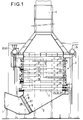
- Figure 1 is a vertical sectional view of a boiler according to the invention.
- Figure 2 shows schematically the water-steam circuit of the heat exchange stages in the case of a recovery boiler with three pressures and overheating and of a combined gas turbine and steam turbine cycle.
- the recovery boiler shown is disposed at the outlet of a gas turbine and conventionally comprises an inlet duct 1 for gases of generally horizontal direction, a deflection duct 2 for the gases connected to the preceding duct 1 and leading to a enclosure 3 of substantially vertical direction and containing a set of substantially horizontal and superimposed heat exchange stages and a smoke evacuation duct 4 at the upper end of enclosure 3.
- At least one heat exchanger 5 is disposed near the outlet of said inlet duct 1. It is inclined, its outlet surface 6 being turned towards the inlet 7 of the pregnant 3.
- the deflection pipe 2 is made of steel, preferably steel with 2.25% chromium and the inlet pipe 1 is made of stainless steel.
- the outlet surface of the inlet duct 1 and the inlet surface of the deflection duct 2 are inclined, turned towards the inlet of the enclosure 3 and connected by an expansion joint 8 and the exchanger 6 is arranged just upstream of the expansion joint 8.
- the exchanger 6 constitutes at least partially a lower heat exchange stage of the boiler.
- the exchanger 6 is double and consists of the HT 28 superheater and the HT 37 superheater.
- this HT 28 superheater and this HT 37 superheater are arranged with the other heat exchange stages in the enclosure 3 of the boiler.
- the invention consists in transfer at least one of these elements at the outlet of the inlet duct 1.
Landscapes
- Engineering & Computer Science (AREA)
- Chemical & Material Sciences (AREA)
- Combustion & Propulsion (AREA)
- Life Sciences & Earth Sciences (AREA)
- Sustainable Development (AREA)
- Sustainable Energy (AREA)
- Physics & Mathematics (AREA)
- Thermal Sciences (AREA)
- Mechanical Engineering (AREA)
- General Engineering & Computer Science (AREA)
- Heat-Exchange Devices With Radiators And Conduit Assemblies (AREA)
- Feeding And Controlling Fuel (AREA)
Abstract
Description
- La présente invention se rapporte à une chaudière de récupération de gaz chauds en particulier en sortie de turbine à gaz.
- Elle concerne plus précisément une chaudière de récupération de gaz chauds comportant un conduit d'entrée des gaz de direction générale sensiblement horizontale, un conduit de déviation des gaz raccordé au conduit précédent et débouchant sur une enceinte de direction sensiblement verticale et contenant un ensemble d'étages d'échange thermique sensiblement horizontaux et superposés et un conduit d'évacuation des fumées à l'extrémité supérieure de l'enceinte.
- Les températures des gaz en sortie d'une turbine à gaz sont très élevées et peuvent actuellement atteindre 650°C. Les conduits d'entrée et de déviation doivent donc être conçus pour résister à ces températures. Ils ne peuvent être réalisés totalement en acier inoxydable compte tenu des problèmes de dilatation qui en résulteraient étant donné leur taille importante. Ils sont donc en général constituées d'une tôle dite tiède constituée d'une tôle d'acier, d'une couche d'isolant thermique et de plaquettes en acier inoxydable disposées sous forme d'écailles. Ainsi la tôle d'acier, en particulier en acier E24, est maintenue à une température d'environ 320°C. Outre sa constitution relativement complexe, une telle tôle pose des problèmes de relative fragilité.
- La présente invention se propose de résoudre ces problèmes et pour ce faire, au moins un échangeur thermique est disposé à proximité de la sortie dudit conduit d'entrée de manière à réduire la température des gaz à la sortie de cet échangeur, ledit échangeur thermique étant incliné et sa surface de sortie étant tournée vers l'entrée de l'enceinte.
- Ainsi, le conduit, où la température est très élevée par exemple d'environ 650°C, est limité au conduit d'entrée de dimension plus réduite. Dans le conduit de déviation règne une température plus basse, par exemple de 560°C, permettant de se dégager dans ce conduit des contraintes d'isolation et en particulier ne nécessitant plus une tôle dite tiède.
- De plus par cet agencement, l'on obtient un meilleur écoulement des gaz en aval de l'échangeur grâce à la perte de charge créée par le passage dans les tubes de l'échangeur, ainsi que par la canalisation des gaz à travers l'échangeur.
- La répartition du flux de gaz est également améliorée en aval de l'échangeur avant l'entrée des gaz dans l'enceinte de la chaudière, grâce à l'inclinaison de l'échangeur et à la disposition que prennent ses chicanes antivibratoires. L'échangeur constitue ainsi un système d'homogénéisation de l'écoulement de gaz.
- Cette disposition inclinée permet de plus de réduire la hauteur de la chaudière.
- La température y étant diminuée, le conduit de déviation peut être en acier, de préférence en acier à 2,25% de chrome.
- Sa dimension étant limitée, le conduit d'entrée peut être en acier inoxydable.
- Avantageusement, la surface de sortie du conduit d'entrée et la surface d'entrée du conduit de déviation sont inclinées, tournées vers l'entrée de l'enceinte et raccordées par un joint de dilatation.
- Une telle inclinaison du joint de dilatation entraîne qu'il ne travaille pas en pur cisaillement sous l'effet de la dilatation verticale de la chaudière supportée en partie haute mais en compression cisaillement ce qui le rend plus fiable.
- Dans ce cas de préférence, l'échangeur est disposé juste en amont du joint de dilatation.
- De préférence, l'échangeur constitue au moins partiellement un étage inférieur d'échange thermique de la chaudière.
- L'invention est décrite ci-dessous en référence aux figures qui ne représentent qu'un mode préféré de l'invention.
- La figure 1 est une vue en coupe verticale d'une chaudière conforme à l'invention.
- La figure 2 schématise le circuit eau-vapeur des étages d'échange thermique dans le cas d'une chaudière de récupération à trois pressions et resurchauffe et d'un cycle combiné de turbine à gaz et de turbine à vapeur.
- La chaudière de récupération représentée est disposée en sortie d'une turbine à gaz et comporte de façon classique un conduit d'entrée 1 des gaz de direction générale sensiblement horizontale, un conduit de déviation 2 des gaz raccordé au conduit précédent 1 et débouchant sur une enceinte 3 de direction sensiblement verticale et contenant un ensemble d'étages d'échange thermique sensiblement horizontaux et superposés et un conduit d'évacuation 4 des fumées à l'extrémité supérieure de l'enceinte 3.
- HP signifiant haute pression, IP pression intermédiaire, LP basse pression, HT haute température, IT température intermédiaire et LT basse température, sont schématisés sur la figure 2:
- un préchauffeur condenseur 10
- un réservoir d'alimentation 11
- un évaporateur déaérateur 12 en parallèle à ce dernier
- une pompe alimentaire HP 20 en sortie du réservoir 11
- une pompe alimentaire IP/LP 30 en sortie du réservoir 11
- des économiseurs HP1,HP2 et HP3, 21, 22 et 23 en série et en sortie de la pompe 20
- un réservoir HP 24
- un évaporateur HP 25 en parallèle au réservoir 24
- des surchauffeurs LT, IT et HT, 26, 27 et 28 en série et en sortie desquels la vapeur est envoyée au corps HP d'une turbine à vapeur
- un économiseur IP1/LP 31 en sortie de la pompe 30
- un économiseur IP2 32 en sortie de l'économiseur 31
- un réservoir IP 33
- un évaporateur IP 34 en parallèle au réservoir 33
- un surchauffeur IP 35
- un resurchauffeur LT 36
- un resurchauffeur HT 37 en sortie duquel la vapeur est envoyée au corps IP d'une turbine à vapeur
- un réservoir LP 40 en sortie de l'économiseur 31
- un évaporateur LP 41 en parallèle du réservoir 40
- un surchauffeur LP 42 en sortie duquel la vapeur est envoyée au corps LP d'une turbine à vapeur.
- Si l'on se réfère à la figure 1, au moins un échangeur thermique 5 est disposé à proximité de la sortie dudit conduit d'entrée 1. Il est incliné, sa surface de sortie 6 étant tournée vers l'entrée 7 de l'enceinte 3.
- Le conduit de déviation 2 est en acier, de préférence en acier à 2,25% de chrome et le conduit d'entrée 1 en acier inoxydable. La surface de sortie du conduit d'entrée 1 et la surface d'entrée du conduit de déviation 2 sont inclinées, tournées vers l'entrée de l'enceinte 3 et raccordés par un joint de dilatation 8 et l'échangeur 6 est disposé juste en amont du joint de dilatation 8.
- L'échangeur 6 constitue au moins partiellement un étage inférieur d'échange thermique de la chaudière. Dans le cas décrit, l'échangeur 6 est double et constitué du surchauffeur HT 28 et du resurchauffeur HT 37.
- Selon l'art antérieur, ce surchauffeur HT 28 et ce resurchauffeur HT 37 sont disposés avec les autres étages d'échange thermique dans l'enceinte 3 de la chaudière. Dans ce cas de réalisation précis, l'invention consiste à transférer au moins l'un de ces éléments en sortie du conduit d'entrée 1.
Claims (7)
Applications Claiming Priority (2)
| Application Number | Priority Date | Filing Date | Title |
|---|---|---|---|
| FR9214317A FR2698681B1 (fr) | 1992-11-27 | 1992-11-27 | Chaudière de récupération en sortie de turbine à gaz. |
| FR9214317 | 1992-11-27 |
Publications (2)
| Publication Number | Publication Date |
|---|---|
| EP0599736A1 true EP0599736A1 (fr) | 1994-06-01 |
| EP0599736B1 EP0599736B1 (fr) | 1997-05-21 |
Family
ID=9435993
Family Applications (1)
| Application Number | Title | Priority Date | Filing Date |
|---|---|---|---|
| EP93402859A Expired - Lifetime EP0599736B1 (fr) | 1992-11-27 | 1993-11-25 | Chaudière de récupération de gaz chauds en particulier en sortie de turbine à gaz |
Country Status (5)
| Country | Link |
|---|---|
| US (1) | US5370086A (fr) |
| EP (1) | EP0599736B1 (fr) |
| DE (1) | DE69310875T2 (fr) |
| ES (1) | ES2101270T3 (fr) |
| FR (1) | FR2698681B1 (fr) |
Cited By (1)
| Publication number | Priority date | Publication date | Assignee | Title |
|---|---|---|---|---|
| AT410473B (de) * | 1995-10-16 | 2003-05-26 | Ae Energietechnik Gmbh | Tragkonstruktion für metallummantelte aufgehängte einrichtungen |
Families Citing this family (3)
| Publication number | Priority date | Publication date | Assignee | Title |
|---|---|---|---|---|
| US5762031A (en) * | 1997-04-28 | 1998-06-09 | Gurevich; Arkadiy M. | Vertical drum-type boiler with enhanced circulation |
| EP1684010A1 (fr) * | 2004-12-30 | 2006-07-26 | Oschatz Gmbh | Four et joint annulaire |
| CN103672841A (zh) * | 2013-12-18 | 2014-03-26 | 乐山市乐锅锅炉有限公司 | 立式水管燃气(黄磷)蒸汽锅炉 |
Citations (3)
| Publication number | Priority date | Publication date | Assignee | Title |
|---|---|---|---|---|
| FR1065284A (fr) * | 1951-06-18 | 1954-05-21 | Procédé et appareillage pour l'amélioration de l'utilisation des chaleurs perdues | |
| FR2374588A1 (fr) * | 1976-12-15 | 1978-07-13 | Foster Wheeler Power Prod | Perfectionnements aux generateurs de vapeur |
| DE4038813A1 (de) * | 1990-12-05 | 1992-06-11 | Siemens Ag | Kesselanordnung |
Family Cites Families (5)
| Publication number | Priority date | Publication date | Assignee | Title |
|---|---|---|---|---|
| US1666276A (en) * | 1927-04-16 | 1928-04-17 | Nat Tube Co | Boiler |
| FR1065234A (fr) * | 1952-03-04 | 1954-05-21 | Alsthom Cgee | Commande manuelle combinée avec l'utilisation d'une source additionnelle d'énergieasservie |
| US3356159A (en) * | 1966-02-16 | 1967-12-05 | Bros Inc | Hihg pressure vapor generator |
| JPS6017967B2 (ja) * | 1978-01-18 | 1985-05-08 | 株式会社日立製作所 | 排熱回収ボイラ装置 |
| JPS6155501A (ja) * | 1984-08-24 | 1986-03-20 | 株式会社日立製作所 | 排熱回収ボイラ |
-
1992
- 1992-11-27 FR FR9214317A patent/FR2698681B1/fr not_active Expired - Fee Related
-
1993
- 1993-11-24 US US08/156,698 patent/US5370086A/en not_active Expired - Fee Related
- 1993-11-25 EP EP93402859A patent/EP0599736B1/fr not_active Expired - Lifetime
- 1993-11-25 ES ES93402859T patent/ES2101270T3/es not_active Expired - Lifetime
- 1993-11-25 DE DE69310875T patent/DE69310875T2/de not_active Expired - Fee Related
Patent Citations (3)
| Publication number | Priority date | Publication date | Assignee | Title |
|---|---|---|---|---|
| FR1065284A (fr) * | 1951-06-18 | 1954-05-21 | Procédé et appareillage pour l'amélioration de l'utilisation des chaleurs perdues | |
| FR2374588A1 (fr) * | 1976-12-15 | 1978-07-13 | Foster Wheeler Power Prod | Perfectionnements aux generateurs de vapeur |
| DE4038813A1 (de) * | 1990-12-05 | 1992-06-11 | Siemens Ag | Kesselanordnung |
Non-Patent Citations (2)
| Title |
|---|
| GANAPATHY: "Heat-recovery boiler design for cogeneration", OIL AND GAS JOURNAL, vol. 83, no. 48, December 1985 (1985-12-01), TULSA US, pages 116 - 125 * |
| GERICKE: "Abhitzedampf-Erzeugersysteme: Bauelemente in verfahrenstechnischen Prozessen", BWK BRENNSTOFF WARME KRAFT, vol. 35, no. 12, December 1983 (1983-12-01), WüRZBURG DE, pages 499 - 504, XP002103730 * |
Cited By (1)
| Publication number | Priority date | Publication date | Assignee | Title |
|---|---|---|---|---|
| AT410473B (de) * | 1995-10-16 | 2003-05-26 | Ae Energietechnik Gmbh | Tragkonstruktion für metallummantelte aufgehängte einrichtungen |
Also Published As
| Publication number | Publication date |
|---|---|
| EP0599736B1 (fr) | 1997-05-21 |
| ES2101270T3 (es) | 1997-07-01 |
| FR2698681B1 (fr) | 1994-12-30 |
| DE69310875T2 (de) | 1997-08-28 |
| US5370086A (en) | 1994-12-06 |
| FR2698681A1 (fr) | 1994-06-03 |
| DE69310875D1 (de) | 1997-06-26 |
Similar Documents
| Publication | Publication Date | Title |
|---|---|---|
| US4380154A (en) | Clean coal power system | |
| JPS6330355B2 (fr) | ||
| FR2690512A1 (fr) | Réacteur à lit fluidisé circulant comportant des échangeurs extérieurs alimentés par la recirculation interne. | |
| EP0599736B1 (fr) | Chaudière de récupération de gaz chauds en particulier en sortie de turbine à gaz | |
| CN104515125B (zh) | 先进的超超临界蒸汽发生器 | |
| FR3000174A1 (fr) | Valorisation energetique des fumees d'un four de fusion | |
| JP2000510218A (ja) | セラミック製フィルタの入口温度の制御 | |
| EP0153214A1 (fr) | Echangeur de chaleur à tubes | |
| CN205560784U (zh) | 四合一硫磺回收余热利用处理装置 | |
| FR2609150A1 (fr) | Generateur thermique poly-combustibles a lit circulant integre, permettant la desulfuration in situ des gaz de combustion | |
| EP0211699B1 (fr) | Brûleur avec des caloducs pour le préchauffage de l'air et du combustible | |
| FR2543663A1 (fr) | Chaudiere de chauffage a condensation | |
| LU83207A1 (fr) | Procede et dispositif de separation des atmospheres gazeuses dans des installations de traitement thermique sous atmosphere | |
| FR2474146A1 (fr) | Installation de chaudiere a lit fluidise | |
| FR2515312A1 (fr) | Installation de recuperation de chaleur pour chaudiere a eau chaude et chaudiere a vapeur avec foyer a gaz | |
| RU2038532C1 (ru) | Котел | |
| KR100197741B1 (ko) | 연속류증기제네레이터내에서 초임계 증기파라미터를 가지는 증기발생방법 및 플랜트 | |
| FR2692966A1 (fr) | Dispositif de réchauffage par combustion de gaz chauds. | |
| SU909434A1 (ru) | Устройство дл сжигани топлива при получении контролируемой атмосферы | |
| SU418621A1 (fr) | ||
| BE449033A (fr) | ||
| FR2694382A1 (fr) | Chaudière à basse température à panneaux radiants catalytiques. | |
| FR2549589A3 (fr) | Recuperateur de chaleur de fumees, a temperature elevee | |
| FR2469661A1 (fr) | Appareil economiseur d'energie thermique destine a etre incorpore dans une installation de chauffage | |
| CN121736779A (zh) | 基于物料全程螺旋推进的内燃式炭化系统 |
Legal Events
| Date | Code | Title | Description |
|---|---|---|---|
| PUAI | Public reference made under article 153(3) epc to a published international application that has entered the european phase |
Free format text: ORIGINAL CODE: 0009012 |
|
| AK | Designated contracting states |
Kind code of ref document: A1 Designated state(s): BE DE ES FR GB IT NL |
|
| 17P | Request for examination filed |
Effective date: 19940914 |
|
| 17Q | First examination report despatched |
Effective date: 19951115 |
|
| GRAG | Despatch of communication of intention to grant |
Free format text: ORIGINAL CODE: EPIDOS AGRA |
|
| GRAH | Despatch of communication of intention to grant a patent |
Free format text: ORIGINAL CODE: EPIDOS IGRA |
|
| GRAH | Despatch of communication of intention to grant a patent |
Free format text: ORIGINAL CODE: EPIDOS IGRA |
|
| GRAA | (expected) grant |
Free format text: ORIGINAL CODE: 0009210 |
|
| AK | Designated contracting states |
Kind code of ref document: B1 Designated state(s): BE DE ES FR GB IT NL |
|
| ITF | It: translation for a ep patent filed | ||
| GBT | Gb: translation of ep patent filed (gb section 77(6)(a)/1977) |
Effective date: 19970520 |
|
| REF | Corresponds to: |
Ref document number: 69310875 Country of ref document: DE Date of ref document: 19970626 |
|
| REG | Reference to a national code |
Ref country code: ES Ref legal event code: FG2A Ref document number: 2101270 Country of ref document: ES Kind code of ref document: T3 |
|
| PLBE | No opposition filed within time limit |
Free format text: ORIGINAL CODE: 0009261 |
|
| STAA | Information on the status of an ep patent application or granted ep patent |
Free format text: STATUS: NO OPPOSITION FILED WITHIN TIME LIMIT |
|
| 26N | No opposition filed | ||
| PGFP | Annual fee paid to national office [announced via postgrant information from national office to epo] |
Ref country code: GB Payment date: 19991012 Year of fee payment: 7 |
|
| PGFP | Annual fee paid to national office [announced via postgrant information from national office to epo] |
Ref country code: NL Payment date: 19991014 Year of fee payment: 7 |
|
| PGFP | Annual fee paid to national office [announced via postgrant information from national office to epo] |
Ref country code: DE Payment date: 19991025 Year of fee payment: 7 |
|
| PGFP | Annual fee paid to national office [announced via postgrant information from national office to epo] |
Ref country code: FR Payment date: 19991027 Year of fee payment: 7 |
|
| PGFP | Annual fee paid to national office [announced via postgrant information from national office to epo] |
Ref country code: ES Payment date: 19991117 Year of fee payment: 7 |
|
| PGFP | Annual fee paid to national office [announced via postgrant information from national office to epo] |
Ref country code: BE Payment date: 19991122 Year of fee payment: 7 |
|
| PG25 | Lapsed in a contracting state [announced via postgrant information from national office to epo] |
Ref country code: GB Free format text: LAPSE BECAUSE OF NON-PAYMENT OF DUE FEES Effective date: 20001125 |
|
| PG25 | Lapsed in a contracting state [announced via postgrant information from national office to epo] |
Ref country code: ES Free format text: LAPSE BECAUSE OF NON-PAYMENT OF DUE FEES Effective date: 20001126 |
|
| PG25 | Lapsed in a contracting state [announced via postgrant information from national office to epo] |
Ref country code: BE Free format text: LAPSE BECAUSE OF NON-PAYMENT OF DUE FEES Effective date: 20001130 |
|
| BERE | Be: lapsed |
Owner name: STEIN INDUSTRIE Effective date: 20001130 |
|
| PG25 | Lapsed in a contracting state [announced via postgrant information from national office to epo] |
Ref country code: NL Free format text: LAPSE BECAUSE OF NON-PAYMENT OF DUE FEES Effective date: 20010601 |
|
| GBPC | Gb: european patent ceased through non-payment of renewal fee |
Effective date: 20001125 |
|
| PG25 | Lapsed in a contracting state [announced via postgrant information from national office to epo] |
Ref country code: FR Free format text: LAPSE BECAUSE OF NON-PAYMENT OF DUE FEES Effective date: 20010731 |
|
| NLV4 | Nl: lapsed or anulled due to non-payment of the annual fee |
Effective date: 20010601 |
|
| PG25 | Lapsed in a contracting state [announced via postgrant information from national office to epo] |
Ref country code: DE Free format text: LAPSE BECAUSE OF NON-PAYMENT OF DUE FEES Effective date: 20010801 |
|
| REG | Reference to a national code |
Ref country code: FR Ref legal event code: ST |
|
| REG | Reference to a national code |
Ref country code: ES Ref legal event code: FD2A Effective date: 20011214 |
|
| PG25 | Lapsed in a contracting state [announced via postgrant information from national office to epo] |
Ref country code: IT Free format text: LAPSE BECAUSE OF NON-PAYMENT OF DUE FEES;WARNING: LAPSES OF ITALIAN PATENTS WITH EFFECTIVE DATE BEFORE 2007 MAY HAVE OCCURRED AT ANY TIME BEFORE 2007. THE CORRECT EFFECTIVE DATE MAY BE DIFFERENT FROM THE ONE RECORDED. Effective date: 20051125 |