EP0599748A1 - Zahnärztlicher Artikulator mit eingerasteter Montageplatte - Google Patents
Zahnärztlicher Artikulator mit eingerasteter Montageplatte Download PDFInfo
- Publication number
- EP0599748A1 EP0599748A1 EP93420461A EP93420461A EP0599748A1 EP 0599748 A1 EP0599748 A1 EP 0599748A1 EP 93420461 A EP93420461 A EP 93420461A EP 93420461 A EP93420461 A EP 93420461A EP 0599748 A1 EP0599748 A1 EP 0599748A1
- Authority
- EP
- European Patent Office
- Prior art keywords
- mounting plate
- plate
- mounting
- articulator
- articulator according
- Prior art date
- Legal status (The legal status is an assumption and is not a legal conclusion. Google has not performed a legal analysis and makes no representation as to the accuracy of the status listed.)
- Granted
Links
- 238000006073 displacement reaction Methods 0.000 claims abstract description 10
- 239000002991 molded plastic Substances 0.000 claims abstract description 7
- 238000000465 moulding Methods 0.000 claims description 7
- 230000002093 peripheral effect Effects 0.000 claims description 4
- 230000000903 blocking effect Effects 0.000 claims description 3
- 210000003141 lower extremity Anatomy 0.000 claims description 3
- 238000013459 approach Methods 0.000 claims description 2
- 230000000284 resting effect Effects 0.000 claims description 2
- 230000002441 reversible effect Effects 0.000 claims description 2
- 238000004519 manufacturing process Methods 0.000 description 5
- 210000001364 upper extremity Anatomy 0.000 description 5
- 230000006978 adaptation Effects 0.000 description 4
- 230000008901 benefit Effects 0.000 description 4
- BASFCYQUMIYNBI-UHFFFAOYSA-N platinum Chemical compound [Pt] BASFCYQUMIYNBI-UHFFFAOYSA-N 0.000 description 4
- 239000002184 metal Substances 0.000 description 3
- 210000004283 incisor Anatomy 0.000 description 2
- 239000000463 material Substances 0.000 description 2
- 239000004033 plastic Substances 0.000 description 2
- 210000002105 tongue Anatomy 0.000 description 2
- 238000005452 bending Methods 0.000 description 1
- 230000005489 elastic deformation Effects 0.000 description 1
- 238000000605 extraction Methods 0.000 description 1
- 230000001815 facial effect Effects 0.000 description 1
- 238000003754 machining Methods 0.000 description 1
Images
Classifications
-
- A—HUMAN NECESSITIES
- A61—MEDICAL OR VETERINARY SCIENCE; HYGIENE
- A61C—DENTISTRY; APPARATUS OR METHODS FOR ORAL OR DENTAL HYGIENE
- A61C11/00—Dental articulators, i.e. for simulating movement of the temporo-mandibular joints; Articulation forms or mouldings
- A61C11/08—Dental articulators, i.e. for simulating movement of the temporo-mandibular joints; Articulation forms or mouldings with means to secure dental casts to articulator
-
- A—HUMAN NECESSITIES
- A61—MEDICAL OR VETERINARY SCIENCE; HYGIENE
- A61C—DENTISTRY; APPARATUS OR METHODS FOR ORAL OR DENTAL HYGIENE
- A61C11/00—Dental articulators, i.e. for simulating movement of the temporo-mandibular joints; Articulation forms or mouldings
- A61C11/02—Dental articulators, i.e. for simulating movement of the temporo-mandibular joints; Articulation forms or mouldings characterised by the arrangement, location or type of the hinge means ; Articulators with pivots
- A61C11/022—Dental articulators, i.e. for simulating movement of the temporo-mandibular joints; Articulation forms or mouldings characterised by the arrangement, location or type of the hinge means ; Articulators with pivots with two adjustable pivoting points, e.g. Argon-type articulators
-
- A—HUMAN NECESSITIES
- A61—MEDICAL OR VETERINARY SCIENCE; HYGIENE
- A61C—DENTISTRY; APPARATUS OR METHODS FOR ORAL OR DENTAL HYGIENE
- A61C11/00—Dental articulators, i.e. for simulating movement of the temporo-mandibular joints; Articulation forms or mouldings
- A61C11/06—Dental articulators, i.e. for simulating movement of the temporo-mandibular joints; Articulation forms or mouldings with incisal guide
Definitions
- the present invention relates to articulators for dentistry, used for carrying out work on occlusal analyzes and dental prostheses.
- articulator described in document WO83 / 02223, comprising a lower member, the front part of which forms a lower plate receiving a removable lower mounting plate intended to support a lower jaw molding and supports an incisal plate, and the posterior part includes two lateral branches each supporting a condylar ball.
- the condylar balls form ball joints on which an upper limb is articulated comprising a posterior hub provided with housings suitable for enclosing the condylar balls.
- the upper limb comprises an upper plate receiving a removable upper mounting plate intended to support an upper jaw molding.
- the upper plate is secured to the rear hub and its front part receives an incisal rod bearing on the incisal plate.
- the lower and upper mounting plates are made of metal, as are the lower and upper members.
- the removable mounting plates are adapted by introducing a screw secured to a mounting plate in a corresponding bore of the lower or upper member plate, and by locking the screw in the bore by a nut. Because the parts are metallic, the positioning of the mounting plates can be precise, so that the articulator can accurately reproduce the mandibular movements of the jaw molds attached to the mounting plates.
- This known articulator is made of metal.
- the general structure of this articulator is not suitable for making a molded plastic material.
- the problem proposed by the present invention is to design a new articulator structure in which special means of adapting mounting plates are provided on the plates of lower and upper limbs, these means having to ensure appropriate positioning accuracy of the plates. mounting, precision high enough to be compatible with the high definition of the mandibular movements that the articulator must reproduce, these means must also be compatible with the production of molded plastic parts.
- the invention also has the advantage of simplifying the handling of the mounting plates, which can be adapted on the articulator or removed from the articulator without long and tedious manipulation of a screw or a tightening nut.
- the invention also has the advantage of simplifying the structure of the articulator, this structure thus being more suitable for being produced in the form of molded plastic parts.
- the first and second directions are advantageously substantially perpendicular to each other.
- the male parts of the attachment and blocking means of the mounting plate are preferably placed on the plate itself, so that their possible rupture does not require the replacement of an entire member of articulator. The difficulty is then that these male parts must not hinder the stable positioning of a mounting plate turned over on a work surface.
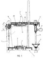
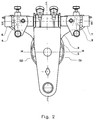
- the articulator generally comprises a lower member 1 on which an upper member 2 is articulated.
- the lower member 1 comprises a lower plate 3 whose front part supports an incisal plate 4.
- the central part of the lower plate 3 allows the adaptation of a lower mounting plate 5.
- the rear part of the lower plate 3 is connected to two vertical lateral branches 6 and 7 whose upper zones each carry a condylar ball, respectively 8 and 9.
- the condylar balls 8 and 9 are arranged opposite one another and protrude from the interior faces of the vertical branches 6 and 7.
- pivot axes 10 and 11 which correspond to the auricular axis and allow the adaptation of a facial arch.
- the upper member 2 can be plugged into the condylar balls 8 and 9, and for this purpose comprises a hub 12 secured to an upper plate 13.
- the front part of the upper plate 13 comprises a guide and blocking device 14 comprising a barrel d vertical axis and a transverse locking screw 15.
- An incisor rod 16 can be introduced and blocked in the barrel to come to bear on the incisor plate 4 and maintain the upper member 2 in the working position, position in which the upper plate 13 is generally parallel to the lower plate 3.
- the central part of the upper plate 13 comprises a positioning device on which an upper mounting plate 17 is fitted.
- the lower 5 and upper 17 mounting plates are intended to support lower and upper jaw moldings respectively.
- the hub 12 comprises, in the vicinity of each of its ends, housings suitable for enclosing the condylar balls 8 and 9.
- the two housings of the hub have a symmetrical arrangement with respect to the median anteroposterior plane II of the device, and are arranged for maintain and guide the upper limb 2 during movements substantially reproducing the anatomical movements of the human jaw.
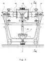
- the upper mounting plate 17 is fixed to the upper plate 13 by an elastic latching means 18, opposing the tearing forces of the mounting plate 17 away from the plate corresponding 13 as shown by arrow 19.
- a first centering means 20 opposes the lateral displacements of the mounting plate 17 in at least one first direction represented by the double arrow 21.
- a second centering means 22 opposes the lateral displacements of the mounting plate 17 in a second direction represented by the sign 23, this second direction being substantially perpendicular to the first direction 21 and parallel to the general plane of the upper plate 13.
- An abutment means 24 opposes the movements of approximation of the mounting plate 17 in the direction of the corresponding plate 13, as shown by arrow 25.
- the elastic latching means 18 comprises a latching lug 26, formed on the holding face 27 of the mounting plate 17 or face intended to come against the upper plate 13.
- a latching hole 39 is provided in the plate upper 13, to receive the snap lug 26 with little play and retain it after engagement, as shown in the figure.
- the latching lug 26 therefore has a hollow cylindrical structure with a side wall split from its end, forming a series of elastically longitudinal tongues flexible, tapered end and shoulder, the shoulder engaging behind the wall of upper plate 13 to oppose the tearing of the mounting plate 17. The plate can however be removed by exerting sufficient traction ensuring the elastic deformation of the tongues of the latching lug 26.
- the first centering means 20 comprises a first cavity 28, formed in the rigid upper plate 13 and open on the receiving face 29 of the plate receiving the mounting plate 13.
- the first cavity 28 is advantageously slightly conical in revolution.
- the first centering means 20 further comprises a first rigid centering lug 32, protruding from the holding face 27 of the mounting plate 13, the first centering lug 32 having a generally conical side wall of revolution at the angle d inclination of the conical lateral face of cavity 28.
- the first centering lug 32 fits without play in said cavity 28.
- the opposite faces 33 and 34 of the side wall of the first centering lug 32 bear without play against the corresponding side faces 30 and 31 of the cavity 28, thus preventing any movement of the mounting plate 17 in the first direction represented by the arrow 21.
- the conical shape of the first cavity 28 and the first lug 32 prevents lateral movement of the mounting plate in all directions.
- the second centering means 22 comprises a second cavity 35 and a second centering lug 36, offset laterally in the first direction 21 relative to the first centering means 20.
- the second cavity 35 is elongated parallel to the first direction 21, and comprises two lateral corner faces on which two inclined lateral walls of the second centering lug 36 engage.
- the second cavity 35 is elongated in the direction of the first direction 21, leaving a clearance 37 in the direction of this first direction 21 between the second cavity 35 and the corresponding second lug 36.
- the second cavity 35 and the corresponding second lug 36 oppose the lateral displacement of the mounting plate in the second direction 23 substantially perpendicular to the first direction 21.
- the play 37 facilitates the molding manufacturing of mounting plates, because the tolerances dimensional spacing between the two pins 32 and 36 need not be tightened.
- the clearance 37 allows lateral movement of the mounting plate in the first direction 21.
- the mounting plate 17 comprises a peripheral rib 38 projecting from its holding face 27, and coming to bear on the corresponding receiving face 29 of the plate 13 to form said abutment means 24.
- the latching means 18 and the two centering means 20 and 22 are advantageously away from the peripheral rib 38. This thus benefits from slight deformations by elastic bending of the plate mounting 17 to cause the engagement without play of the centering pins 32 and 36 in the corresponding cavities 28 and 35.
- the elastic latching means 18 is advantageously arranged in the central zone of mounting plate 17, and the first and second centering means 20 and 22 are opposite on either side of the elastic latching means 18, as shown the figure.
- the elastic snap-fastening means 18 is slightly closer to one of the two centering means 20 or 22. This produces a unique position for adapting the mounting plate to the corresponding plate.
- the mounting plates 17 and 5 and the corresponding plates 13 and 3 can be made of molded plastic, while guaranteeing sufficient precision in maintaining and positioning the mounting plate on the plate. .
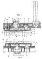
- FIG. 5 there is shown the adaptation of the lower mounting plate 5 on the lower plate 3.
- Similar means of positioning which are identified by similar reference numerals, namely: an elastic snap latch 126, protruding from the retaining face 127 and engaging in a corresponding snap-hole 139 open on the receiving face 129 of the lower plate 3, a first centering lug 132 protruding from the retaining face 127 and engaged in a first cavity 128, a second centering lug 136 projecting from the retaining face 127 and engaged in a second cavity 135, and a peripheral rib 138 also projecting from the retaining face 127, and coming to bear on the corresponding receiving face 129 of the plate 3.
- an elastic snap latch 126 protruding from the retaining face 127 and engaging in a corresponding snap-hole 139 open on the receiving face 129 of the lower plate 3
- a first centering lug 132 protruding from the retaining face 127 and engaged in a first cavity 128,
- the latching lug 26 or 126 with hollow cylindrical structure is associated with a respective corresponding cylindrical shim 40 or 41.
- Each shim 40 or 41 is removable and s' forcibly adapts in the central hollow of the respective latching lug 26 or 126.
- the shim When the shim is inserted, it prohibits the bringing together of the side wall portions of latching lug, thus prohibiting the extraction of the lug locking out of its corresponding hole 39 or 139, thus ensuring the locking of the mounting plate on the articulator and preventing any axial movement of the respective mounting plate 5 or 17.
- each wedge is provided with a respective gripping head 42 or 43, and is accessible from the outer face of the plate opposite the mounting plates, as shown in FIGS. 4 and 5.
- the prominent male elements forming part of the means for attaching the mounting plate to the corresponding plate are preferably arranged on the corresponding holding face 27 or 127 of the mounting plate, as shown in the figures.
- the reason is that such male means are liable to be degraded more easily than female means during handling, as a result of impacts, so that if a male means is broken, it suffices to change the mounting plate, without having to modify the corresponding stage or the whole member of the articulator.
- the mounting plates When in use, the mounting plates must either be adapted to the corresponding plate by the hooking means, or turned over and placed on a work surface according to their holding face. In this last position placed on a work surface, the male hooking elements then constitute a discomfort, preventing the plate from resting on the plane in a stable position.
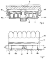
- each mounting plate comprises support elements such as the lateral elements 150 and 151, protruding from its holding face at a height H1 greater than the height H2 of the male fastening means.
- the support elements 150 and 151 are arranged to escape the corresponding plate in the assembled position, so that they do not oppose when the mounting plate approaches the plate.
- the support elements 150 and 151 are shaped to provide stable support when the mounting plate rests by these support elements on a work surface 155.
- the corresponding plate such as the bottom plate 3 has a width less than the width of the mounting plate 5.
- the elements of support 150 and 151 are then arranged at the lateral ends of the mounting plate 5, and engage on either side of the respective lateral edges 152 and 153 of the plate 3.
- Such support elements 150 and 151 can be provided in various forms, for example a set of at least four support rods or columns forming a stable support quadrilateral.
- the support elements 150 and 151 advantageously comprise two portions of arcuate ribs running along the lateral edges of the retaining face 27 or 127 of mounting plate 17 or 5, and protruding on either side of the median transverse plane MM of the mounting plate 5.
- the ends of the arcuate ribs forming the support elements 150 and 151 come to bear against the edges 152 and 153 of the corresponding plate 3 or 13 of articulator , thus participating in the transverse holding and in the rotation locking of the mounting plate 5 or 17.
- edges 152 and 153 of the plate 3 are advantageously divergent in the assembly area of the mounting plate 5.
- the arcuate ribs forming the support elements 150 and 151 allow the mounting of the plate. mounting 5 in one direction, preventing incorrect mounting.
- FIG. 6 it can be seen that the support elements 150 and 151 do not oppose the assembly of the mounting plate 5 on the plate 3, while in FIG. 7 they provide stable support for the plate mounting 5 overturned and placed on a work surface 155, allowing work on a molding 154 fixed on the mounting plate 5.
Landscapes
- Health & Medical Sciences (AREA)
- Oral & Maxillofacial Surgery (AREA)
- Dentistry (AREA)
- Epidemiology (AREA)
- Life Sciences & Earth Sciences (AREA)
- Animal Behavior & Ethology (AREA)
- General Health & Medical Sciences (AREA)
- Public Health (AREA)
- Veterinary Medicine (AREA)
- Dental Prosthetics (AREA)
- Dental Tools And Instruments Or Auxiliary Dental Instruments (AREA)
Applications Claiming Priority (4)
| Application Number | Priority Date | Filing Date | Title |
|---|---|---|---|
| FR9214272A FR2698262B1 (fr) | 1992-11-24 | 1992-11-24 | Articulateur dentaire à plaques de montage encliquetées. |
| FR9214272 | 1992-11-24 | ||
| FR9301694A FR2701384B1 (fr) | 1993-02-10 | 1993-02-10 | Articulateur dentaire à plaques de montage stabilisées. |
| FR9301694 | 1993-02-10 |
Publications (2)
| Publication Number | Publication Date |
|---|---|
| EP0599748A1 true EP0599748A1 (de) | 1994-06-01 |
| EP0599748B1 EP0599748B1 (de) | 1997-10-08 |
Family
ID=26229912
Family Applications (1)
| Application Number | Title | Priority Date | Filing Date |
|---|---|---|---|
| EP19930420461 Expired - Lifetime EP0599748B1 (de) | 1992-11-24 | 1993-11-22 | Zahnärztlicher Artikulator mit eingerasteter Montageplatte |
Country Status (3)
| Country | Link |
|---|---|
| EP (1) | EP0599748B1 (de) |
| DE (1) | DE69314435T2 (de) |
| ES (1) | ES2109458T3 (de) |
Citations (5)
| Publication number | Priority date | Publication date | Assignee | Title |
|---|---|---|---|---|
| US3510947A (en) * | 1968-07-19 | 1970-05-12 | J T Jelenko & Co Inc | Interchangeable dental articulator |
| DE7900692U1 (de) * | 1979-06-21 | Rosenberger, Reinhold, 4100 Duisburg | Zahntechnische Vorrichtung zur Fixierung eines Gebiümodelles an einem Artikulatorteil | |
| DE2922045A1 (de) * | 1979-05-30 | 1980-12-11 | Alfred Strunz | Vorrichtung fuer die herstellung von zahnprothetik |
| US4319875A (en) * | 1980-11-17 | 1982-03-16 | Beckwith Edward K | Detachable fastener for joining impressions of a mouth onto a dental articulator |
| DE3714189A1 (de) * | 1987-04-29 | 1988-11-10 | Gerd Haker | Loesbare befestigungseinrichtung fuer ein kieferabgussmodell und einen artikulationssockel bei der zahnersatzherstellung |
-
1993
- 1993-11-22 EP EP19930420461 patent/EP0599748B1/de not_active Expired - Lifetime
- 1993-11-22 DE DE1993614435 patent/DE69314435T2/de not_active Expired - Lifetime
- 1993-11-22 ES ES93420461T patent/ES2109458T3/es not_active Expired - Lifetime
Patent Citations (5)
| Publication number | Priority date | Publication date | Assignee | Title |
|---|---|---|---|---|
| DE7900692U1 (de) * | 1979-06-21 | Rosenberger, Reinhold, 4100 Duisburg | Zahntechnische Vorrichtung zur Fixierung eines Gebiümodelles an einem Artikulatorteil | |
| US3510947A (en) * | 1968-07-19 | 1970-05-12 | J T Jelenko & Co Inc | Interchangeable dental articulator |
| DE2922045A1 (de) * | 1979-05-30 | 1980-12-11 | Alfred Strunz | Vorrichtung fuer die herstellung von zahnprothetik |
| US4319875A (en) * | 1980-11-17 | 1982-03-16 | Beckwith Edward K | Detachable fastener for joining impressions of a mouth onto a dental articulator |
| DE3714189A1 (de) * | 1987-04-29 | 1988-11-10 | Gerd Haker | Loesbare befestigungseinrichtung fuer ein kieferabgussmodell und einen artikulationssockel bei der zahnersatzherstellung |
Also Published As
| Publication number | Publication date |
|---|---|
| ES2109458T3 (es) | 1998-01-16 |
| EP0599748B1 (de) | 1997-10-08 |
| DE69314435T2 (de) | 1998-05-14 |
| DE69314435D1 (de) | 1997-11-13 |
Similar Documents
| Publication | Publication Date | Title |
|---|---|---|
| FR2552318A1 (fr) | Ensemble a plateau de moulage dentaire | |
| FR2859510A1 (fr) | Structure d'assemblage | |
| EP0382771A1 (de) | Stift zum anbringen auf dem endostalen teil eines zahnimplantats. | |
| EP3589227B1 (de) | Vorrichtung zur mandibulären befestigung eines ortsmarkers | |
| EP0156089B1 (de) | Verfahren zum Herstellen und Zusammenbauen von zwischen Flanschen drehenden Organen und erhaltene Produkte insbesondere geeignet zum Anspannen und Wickeln der Kette in Schaltgetrieben für Fahrräder und gleichartige Fahrzeuge | |
| EP0599748B1 (de) | Zahnärztlicher Artikulator mit eingerasteter Montageplatte | |
| EP0223891B1 (de) | Formeinrichtung zum Spritzgiessen von Kunststoffen | |
| EP0116507B1 (de) | Zahnärztlicher Artikulator | |
| FR2701384A1 (fr) | Articulateur dentaire à plaques de montage stabilisées. | |
| EP0109404B1 (de) | Dentalartikulator | |
| EP3551121A1 (de) | Intraorale vorrichtung mit zwei gelenkigen zahnausrichtern | |
| FR2698262A1 (fr) | Articulateur dentaire à plaques de montage encliquetées. | |
| EP0599747B1 (de) | Zahnärztlicher Artikulator mit austauschbaren Stützkeilen | |
| FR2745998A1 (fr) | Support de prothese dentaire avec mecanisme anti-rotation | |
| EP0097660B1 (de) | Gebissartikulator | |
| EP1827869B1 (de) | Schreibinstrument mit patronenhalter | |
| FR2606271A1 (fr) | Porte-empreinte reglable universel | |
| EP0130152B1 (de) | Fahrradpedal | |
| EP1577698A1 (de) | Brillenfassung mit magnetischer Linsenanordnung | |
| BE1011907A3 (fr) | Conditionnement pour implant intraoculaire souple. | |
| FR2726865A1 (fr) | Collier a cheville integree pour la fixation murale, d'un conduit ou tube | |
| FR2590157A1 (fr) | Procede et dispositif pour le controle du montage des modeles mandibulaires sur un articulateur dentaire | |
| FR2558410A1 (fr) | Machine a mouler des matieres plastiques par injection equipee d'un dispositif de fermeture de moule supporte par l'intermediaire de son porte-moule fixe et d'une plaque formant butee | |
| FR2599243A1 (fr) | Dispositif de fixation d'une prothese dentaire partielle amovible et procede de fixation d'un tel organe. | |
| FR2726998A1 (fr) | Articulateur dentaire arcon - non-arcon |
Legal Events
| Date | Code | Title | Description |
|---|---|---|---|
| PUAI | Public reference made under article 153(3) epc to a published international application that has entered the european phase |
Free format text: ORIGINAL CODE: 0009012 |
|
| AK | Designated contracting states |
Kind code of ref document: A1 Designated state(s): DE ES FR GB IT SE |
|
| RAP3 | Party data changed (applicant data changed or rights of an application transferred) |
Owner name: GERBELOT-BARRILLON, PIERRE |
|
| 17P | Request for examination filed |
Effective date: 19940920 |
|
| 17Q | First examination report despatched |
Effective date: 19960930 |
|
| GRAG | Despatch of communication of intention to grant |
Free format text: ORIGINAL CODE: EPIDOS AGRA |
|
| GRAH | Despatch of communication of intention to grant a patent |
Free format text: ORIGINAL CODE: EPIDOS IGRA |
|
| GRAH | Despatch of communication of intention to grant a patent |
Free format text: ORIGINAL CODE: EPIDOS IGRA |
|
| GRAA | (expected) grant |
Free format text: ORIGINAL CODE: 0009210 |
|
| AK | Designated contracting states |
Kind code of ref document: B1 Designated state(s): DE ES FR GB IT SE |
|
| REF | Corresponds to: |
Ref document number: 69314435 Country of ref document: DE Date of ref document: 19971113 |
|
| ITF | It: translation for a ep patent filed | ||
| REG | Reference to a national code |
Ref country code: ES Ref legal event code: FG2A Ref document number: 2109458 Country of ref document: ES Kind code of ref document: T3 |
|
| GBT | Gb: translation of ep patent filed (gb section 77(6)(a)/1977) |
Effective date: 19980112 |
|
| PLBE | No opposition filed within time limit |
Free format text: ORIGINAL CODE: 0009261 |
|
| STAA | Information on the status of an ep patent application or granted ep patent |
Free format text: STATUS: NO OPPOSITION FILED WITHIN TIME LIMIT |
|
| 26N | No opposition filed | ||
| REG | Reference to a national code |
Ref country code: GB Ref legal event code: IF02 |
|
| REG | Reference to a national code |
Ref country code: FR Ref legal event code: TP |
|
| REG | Reference to a national code |
Ref country code: GB Ref legal event code: 732E |
|
| PGFP | Annual fee paid to national office [announced via postgrant information from national office to epo] |
Ref country code: FR Payment date: 20121207 Year of fee payment: 20 |
|
| PGFP | Annual fee paid to national office [announced via postgrant information from national office to epo] |
Ref country code: SE Payment date: 20121107 Year of fee payment: 20 Ref country code: GB Payment date: 20121120 Year of fee payment: 20 Ref country code: IT Payment date: 20121128 Year of fee payment: 20 Ref country code: ES Payment date: 20121025 Year of fee payment: 20 |
|
| PGFP | Annual fee paid to national office [announced via postgrant information from national office to epo] |
Ref country code: DE Payment date: 20130128 Year of fee payment: 20 |
|
| REG | Reference to a national code |
Ref country code: DE Ref legal event code: R071 Ref document number: 69314435 Country of ref document: DE |
|
| REG | Reference to a national code |
Ref country code: GB Ref legal event code: PE20 Expiry date: 20131121 |
|
| REG | Reference to a national code |
Ref country code: SE Ref legal event code: EUG |
|
| PG25 | Lapsed in a contracting state [announced via postgrant information from national office to epo] |
Ref country code: DE Free format text: LAPSE BECAUSE OF EXPIRATION OF PROTECTION Effective date: 20131123 Ref country code: GB Free format text: LAPSE BECAUSE OF EXPIRATION OF PROTECTION Effective date: 20131121 |
|
| REG | Reference to a national code |
Ref country code: ES Ref legal event code: FD2A Effective date: 20140307 |
|
| PG25 | Lapsed in a contracting state [announced via postgrant information from national office to epo] |
Ref country code: ES Free format text: LAPSE BECAUSE OF EXPIRATION OF PROTECTION Effective date: 20131123 |