EP0599760B1 - Anlage zum Reduzieren von Eisenerzen in einer durch Reduktionsgase aufgewirbelten Schicht aus festen Teilchen - Google Patents
Anlage zum Reduzieren von Eisenerzen in einer durch Reduktionsgase aufgewirbelten Schicht aus festen Teilchen Download PDFInfo
- Publication number
- EP0599760B1 EP0599760B1 EP93470030A EP93470030A EP0599760B1 EP 0599760 B1 EP0599760 B1 EP 0599760B1 EP 93470030 A EP93470030 A EP 93470030A EP 93470030 A EP93470030 A EP 93470030A EP 0599760 B1 EP0599760 B1 EP 0599760B1
- Authority
- EP
- European Patent Office
- Prior art keywords
- particles
- reactor
- segregation
- bed
- prereduction
- Prior art date
- Legal status (The legal status is an assumption and is not a legal conclusion. Google has not performed a legal analysis and makes no representation as to the accuracy of the status listed.)
- Expired - Lifetime
Links
- XEEYBQQBJWHFJM-UHFFFAOYSA-N Iron Chemical compound [Fe] XEEYBQQBJWHFJM-UHFFFAOYSA-N 0.000 title claims abstract description 121
- 239000002245 particle Substances 0.000 title claims abstract description 103
- 229910052742 iron Inorganic materials 0.000 title claims abstract description 59
- 239000007787 solid Substances 0.000 title claims abstract description 30
- 230000009467 reduction Effects 0.000 title claims description 39
- 238000009434 installation Methods 0.000 title description 44
- 239000007789 gas Substances 0.000 claims abstract description 51
- 238000005204 segregation Methods 0.000 claims abstract description 36
- 238000002309 gasification Methods 0.000 claims abstract description 14
- QVGXLLKOCUKJST-UHFFFAOYSA-N atomic oxygen Chemical compound [O] QVGXLLKOCUKJST-UHFFFAOYSA-N 0.000 claims abstract description 11
- 239000001301 oxygen Substances 0.000 claims abstract description 11
- 229910052760 oxygen Inorganic materials 0.000 claims abstract description 11
- UFHFLCQGNIYNRP-UHFFFAOYSA-N Hydrogen Chemical compound [H][H] UFHFLCQGNIYNRP-UHFFFAOYSA-N 0.000 claims description 10
- 239000003575 carbonaceous material Substances 0.000 claims description 10
- 239000001257 hydrogen Substances 0.000 claims description 10
- 229910052739 hydrogen Inorganic materials 0.000 claims description 10
- 238000000926 separation method Methods 0.000 claims description 5
- 230000032258 transport Effects 0.000 claims description 4
- 238000005192 partition Methods 0.000 claims description 3
- 238000000605 extraction Methods 0.000 abstract description 5
- 238000006722 reduction reaction Methods 0.000 description 36
- 239000000571 coke Substances 0.000 description 15
- 238000005243 fluidization Methods 0.000 description 14
- 239000000463 material Substances 0.000 description 11
- 230000004927 fusion Effects 0.000 description 9
- 238000000034 method Methods 0.000 description 8
- 230000008569 process Effects 0.000 description 8
- OKTJSMMVPCPJKN-UHFFFAOYSA-N Carbon Chemical compound [C] OKTJSMMVPCPJKN-UHFFFAOYSA-N 0.000 description 4
- 229910001018 Cast iron Inorganic materials 0.000 description 4
- 229910052799 carbon Inorganic materials 0.000 description 4
- 239000000203 mixture Substances 0.000 description 4
- XLYOFNOQVPJJNP-UHFFFAOYSA-N water Chemical compound O XLYOFNOQVPJJNP-UHFFFAOYSA-N 0.000 description 4
- 238000004519 manufacturing process Methods 0.000 description 3
- 230000015572 biosynthetic process Effects 0.000 description 2
- 239000003245 coal Substances 0.000 description 2
- 230000000694 effects Effects 0.000 description 2
- 238000002347 injection Methods 0.000 description 2
- 239000007924 injection Substances 0.000 description 2
- 239000007788 liquid Substances 0.000 description 2
- 239000002184 metal Substances 0.000 description 2
- 229910052751 metal Inorganic materials 0.000 description 2
- 210000000056 organ Anatomy 0.000 description 2
- 239000000047 product Substances 0.000 description 2
- 238000011144 upstream manufacturing Methods 0.000 description 2
- KRQUFUKTQHISJB-YYADALCUSA-N 2-[(E)-N-[2-(4-chlorophenoxy)propoxy]-C-propylcarbonimidoyl]-3-hydroxy-5-(thian-3-yl)cyclohex-2-en-1-one Chemical compound CCC\C(=N/OCC(C)OC1=CC=C(Cl)C=C1)C1=C(O)CC(CC1=O)C1CCCSC1 KRQUFUKTQHISJB-YYADALCUSA-N 0.000 description 1
- CWYNVVGOOAEACU-UHFFFAOYSA-N Fe2+ Chemical compound [Fe+2] CWYNVVGOOAEACU-UHFFFAOYSA-N 0.000 description 1
- 229910000805 Pig iron Inorganic materials 0.000 description 1
- 238000003723 Smelting Methods 0.000 description 1
- 229910000831 Steel Inorganic materials 0.000 description 1
- 241001080024 Telles Species 0.000 description 1
- 238000009825 accumulation Methods 0.000 description 1
- 239000000654 additive Substances 0.000 description 1
- 238000005054 agglomeration Methods 0.000 description 1
- 230000002776 aggregation Effects 0.000 description 1
- 238000013019 agitation Methods 0.000 description 1
- 230000008901 benefit Effects 0.000 description 1
- 230000000903 blocking effect Effects 0.000 description 1
- 238000006243 chemical reaction Methods 0.000 description 1
- -1 coal Chemical compound 0.000 description 1
- 238000004939 coking Methods 0.000 description 1
- 238000010276 construction Methods 0.000 description 1
- 230000006866 deterioration Effects 0.000 description 1
- 239000012467 final product Substances 0.000 description 1
- 239000010419 fine particle Substances 0.000 description 1
- 238000000265 homogenisation Methods 0.000 description 1
- 239000012535 impurity Substances 0.000 description 1
- 238000002844 melting Methods 0.000 description 1
- 230000008018 melting Effects 0.000 description 1
- 239000012429 reaction media Substances 0.000 description 1
- 238000010405 reoxidation reaction Methods 0.000 description 1
- 230000000717 retained effect Effects 0.000 description 1
- 239000011343 solid material Substances 0.000 description 1
- 241000894007 species Species 0.000 description 1
- 239000010959 steel Substances 0.000 description 1
Images

Classifications
-
- C—CHEMISTRY; METALLURGY
- C21—METALLURGY OF IRON
- C21B—MANUFACTURE OF IRON OR STEEL
- C21B13/00—Making spongy iron or liquid steel, by direct processes
- C21B13/0033—In fluidised bed furnaces or apparatus containing a dispersion of the material
-
- C—CHEMISTRY; METALLURGY
- C22—METALLURGY; FERROUS OR NON-FERROUS ALLOYS; TREATMENT OF ALLOYS OR NON-FERROUS METALS
- C22B—PRODUCTION AND REFINING OF METALS; PRETREATMENT OF RAW MATERIALS
- C22B5/00—General methods of reducing to metals
- C22B5/02—Dry methods smelting of sulfides or formation of mattes
- C22B5/12—Dry methods smelting of sulfides or formation of mattes by gases
- C22B5/14—Dry methods smelting of sulfides or formation of mattes by gases fluidised material
-
- Y—GENERAL TAGGING OF NEW TECHNOLOGICAL DEVELOPMENTS; GENERAL TAGGING OF CROSS-SECTIONAL TECHNOLOGIES SPANNING OVER SEVERAL SECTIONS OF THE IPC; TECHNICAL SUBJECTS COVERED BY FORMER USPC CROSS-REFERENCE ART COLLECTIONS [XRACs] AND DIGESTS
- Y02—TECHNOLOGIES OR APPLICATIONS FOR MITIGATION OR ADAPTATION AGAINST CLIMATE CHANGE
- Y02P—CLIMATE CHANGE MITIGATION TECHNOLOGIES IN THE PRODUCTION OR PROCESSING OF GOODS
- Y02P10/00—Technologies related to metal processing
- Y02P10/10—Reduction of greenhouse gas [GHG] emissions
- Y02P10/134—Reduction of greenhouse gas [GHG] emissions by avoiding CO2, e.g. using hydrogen
Definitions
- the invention relates to the field of reduction of iron ore, especially in facilities operating with a circulating fluidized bed.
- fusion reduction or “smelting” processes reduction ".
- One of them combines two reactors. One of these reactors produced from iron ore ore very greatly reduced to the metallic state, which is placed in the oven in the second reactor to be transformed into cast iron liquid. The gas circuits of these two reactors can be related to each other, or be completely independent.
- a particular embodiment of such a process is described for example in European Patent EP 255,180 and in French Patent Application No. 91.14467.
- the reduction reaction of the iron ore is carried out by reacting a circulating fluidized bed, formed by particles of ore being reduced and of semi-coke, with a reducing gas (mixture CO / CO 2 / H 2 / H 2 O) which also ensures the fluidization of solid materials. This takes place in the first part of the reactor.
- the gases loaded with particles of ore being reduced and semi-coke then pass through a cyclone.
- the gases then escape from the reactor, while the particles descend into a gasifier, where carbon or oxygen are introduced separately or together in order to form CO and hydrogen which will contribute to the reduction of the ore.
- the solids and gases then return to the first part of the reactor, from which a fraction of the solids (reduced ore and semi-coke) is extracted periodically or continuously.
- New ore is introduced into the material stream between the cyclone and the gasifier.
- the gases which have escaped from the cyclone are purified and reintroduced into the gasifier and at the base of the first part of the reactor, where they can replay their role of fluidizing and reaction medium.
- Solids extracted from the reduction reactor which has just been described are then directed to the fusion reactor to help produce cast iron liquid.
- these materials are composed for the essence of a greatly reduced iron ore mixture (at least about 75%) and semi-coke with incidentally other non-ferrous materials: impurities from ore and any additives.
- Their semi-coke content (which can reach 50%) is actually higher than necessary to form cast iron (around 5 to 25%). This would lead to excessive production of carbonaceous gases in the fusion reactor, and a high consumption of carbonaceous materials from the entire installation, consumption which it is desirable to lower.
- the object of the invention is to propose a process for the reduction of iron ore based on the principles described above, and which makes it possible on the one hand to considerably reduce the quantity of metallic iron passing through the gasifier, and on the other hand to enrich the materials extracted from the installation with metallic iron.
- the subject of the invention is
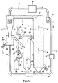
- FIG. 1 represents an example of installation, derived from the installations which are the subject of the documents cited above. It comprises a pre-reduction reactor 1 containing a circulating fluidized bed 2 formed from particles of iron ore being reduced, particles of metallic iron resulting from this reduction, and particles of semi-coke.
- a gas-permeable support 3, such as a grid, is placed at the bottom of the prereduction reactor 1 to prevent large particles from descending into the bottom of the reactor 1.
- a gas stream of fluidization crosses the assembly of the installation, and in particular the prereduction reactor 1, as symbolized by the arrows 4, 4 ′, 4 ".
- This fluidizing gas is a reducing gas, namely a CO / CO 2 / H 2 / H 2 O mixture which is injected at the base of reactor 1 through a pipe 5. It moves at a speed of the order of 2 to 10 m / s.
- the iron ore particles initially the oxidized natural state undergoes a reduction in metallic iron by the CO and the hydrogen of the fluidization gases.
- the gases and the solid particles escape from the prereduction reactor 1 via a pipe 6 and then enter a cyclone 7, in which they are separated from each other.
- the g az are discharged from the cyclone via a pipe 8, while the solid particles fall back into the lower part of the cyclone 7 and continue their journey in the installation, as will be explained below.
- the gases are purified from water vapor and from the CO 2 which they contain in an appropriate reactor 9 of a type known in itself, are returned by suitable means symbolized by the pump 10 and the pipe 11 towards the base of the reactor 1 after having passed through a preheater 12, and are again used for the fluidization and reduction of the ore inside the reactor 1.
- the installation also comprises, placed on the material circuit between the cyclone 7 and the pre-reduction reactor 1, a gasifier 13.
- a gasifier 13 This has the function of generating the gases used for the fluidization and to the circulation of particles, and to provide the energy necessary to balance the heat balance.
- injections of oxygen and carbonaceous materials, such as coal are carried out there, these carbonaceous materials being in excess.
- the temperature of the gases is of the order of 950 ° C., and the proportion of CO 2 and water vapor which they contain under steady conditions is around 30 to 40%.
- the carbonaceous materials 14 contained in a hopper 15, are introduced into the gasifier 13 through a line 16, and their admission is controlled by a valve 17.
- Oxygen, contained in a reservoir 18, is likewise blown into the gasifier 13 through a pipe 19, and its admission is controlled by a valve 20.
- CO is created by reaction of carbonaceous materials with the oxygen inside the gasifier 13. It is also possible, as proposed in the application FR 91 14467 already cited, form CO and hydrogen in a burner upstream of which lines 16 and 19 meet, so before the materials carbonaceous and oxygen do not enter the gasifier 13. This last configuration avoids reoxidation in the gasifier 13 of iron particles in contact with oxygen not yet combined with carbon. In the example shown, it is also at the gasifier 13 that place the introduction of new iron ore particles 21 in the material circuit. These particles are stored in a hopper 22 and introduced into the gasifier by a line 23 provided with a valve 24.
- the introduction into the gasifier 13 of the various solid particles and the formation of gases has the effect that in the gasifier 13, a fluidized bed 25 is formed solid particles, just like in the reactor of prereduction 1.
- the fluidization of particles is also provided by gases from a line 26, derived from line 11, and opening into the bottom of the gasifier 13.
- a gas permeable grid 27 prevents any particles too large to be fluidized only descend into line 26 and obstruct it.
- the gasifier 13 and the prereduction reactor 1 are connected by a pipe 28, and the gases and the particles composing the fluidized bed can thus circulate reactor to another.
- the solid matter resulting from the operation can be extracted from the installation so intermittent or continuous by means of a pipe 29 provided a valve 30 and connected to the base of the reactor prereduction 1.
- These materials usually consist of ore reduced to at least 75% and semi-coke, and are intended to be placed in a non-melting reactor shown where the cast iron will be produced.
- these material extraction means can be kept, but they will collect in priority particles too large to have been fluidized and which fell into the lower part of the reactor pre-reduction 1.
- the part bottom of cyclone 7 is directly connected to the gasifier 13, and the particles which were carried in the bed fluidized circulating before cyclone 7 therefore pass into the gasifier without distinction.
- the lower part of cyclone 7 leads into a third reactor 31 called “compartment of segregation ".
- this segregation compartment 31 we achieves gas circulation conditions such as particles of metallic iron and strongly iron ore reduced form the lower part of a dense fluidized bed 32, while the semi-coke and finer particles still little or not reduced ore particles are mostly driven by the gas stream, and pass in the gasifier 13 by using line 33 which connects to segregation compartment 31.
- the gases ensuring the fluidization of this dense bed 32 can advantageously (but not necessarily) also be taken from the pipe 11 and blown into the bottom of the segregation compartment 31 by a pipe 84.
- a gas permeable grid 34 placed in the lower part compartment 31 prevents particles from falling back into driving 84.
- Intermittent or continuous evacuation of materials making up the dense bed 32 is produced by a line 35 provided with a valve 36. These materials are therefore made up, for the most part, of metallic iron and very greatly reduced ore, and are ready to be placed in the fusion reactor.
- the compartment segregation 31 allows for efficient separation between iron and carbonaceous materials and thus limiting the quantity of carbonaceous materials which will be placed in the fusion reactor with iron ore strongly reduced and metallic iron.
- the exhaust pipe 29 usually present at the bottom of the pre-reduction reactor 1 can advantageously be kept to avoid possible accumulation in the bottom of reactor 1 of large agglomerated iron particles. It can also allow provide a product with higher carbon content than necessary that extracted at the level of segregation compartment 31 and can be mixed with it to optimize the conditions of operation of the fusion reactor.
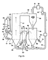
- FIG. 2 The configuration illustrated in Figure 2 is distinguishes, according to the invention, from that of FIG. 1 in that that the respective positions of the prereduction reactor and of the gasifier with respect to the cyclone are reversed, and in this that the segregation compartment is placed between the pre-reduction reactor and gasifier.
- the gasifier 37 receives, as in the example of the Figure 1, iron ore 38 stored in a hopper 39 and conveyed by a pipe 40 fitted with a valve 41, carbonaceous materials 42 stored in a hopper 43 and conveyed by a pipe 44 provided with a valve 45, and the oxygen stored in a container 46 and blown in by a line 47 provided with a valve 48.
- the gasifier 37 have therefore takes place the formation of CO and hydrogen and the circulation of bed 83 of ore particles and semi-coke. New ore begins to be reduced to wüstite.
- the solids and gas are directed through line 49 to cyclone 50 that separates them from each other.
- the gases are evacuated by line 51, decarbonated and dried in reactor 52, and returned by the pump 53 and the line 54 to the base of the various reactors of the installation to ensure the fluidization of solid particles, after passing through the preheater 55.
- solids, ore in process reduction and semi-coke they pass from cyclone 50 in the reduction reactor 56. They are fluidized there by gases (mainly CO and hydrogen) brought to the bottom of the reactor 56 via line 57, gases which are also used for complete the reduction of metallic iron ore.
- gases mainly CO and hydrogen
- the fluidization of the particles in the reactor 56 is made so as to form a bed circulating, which is sent by a pipe 60 in a segregation compartment 61. This compartment receives also, in its lower part, reducing gases of preferably taken from line 54 through line 62, and is fitted with a gas permeable grille 63.
- the conditions hydrodynamics in this compartment 61 are such that the highly reduced iron and ore particles form a dense bed 64 in its lower part, while the carbonaceous matter and fine particles of ore not still reduced remain fluidized in the upper part from reactor 61 above dense bed 64, and are sent by overflow using a line 65 in the gasifier 37 to continue their treatment.
- like gases are preferably highly reducing, they contribute to the completion of the ore reduction.
- the particles making up the lower part of the fluidized layer 64 are extracted continuously or intermittently by the line 66 provided with a valve 67, and are directed towards the fusion reactor for the production of pig iron.
- the rest of the purified gases circulating in line 54 can be directed through line 68 to the base of the gasifier 37, which has in its lower part a grid 69 avoiding blockage of the pipe 68 by any large particles present in the gasifier 37.
- This configuration like the previous one, allows you to considerably limit the amount of metallic iron circulating in the gasifier 37, since it is mostly retained in the segregation compartment 61.
- the configuration of Figure 2 where the compartment segregation is placed between the pre-reduction reactor and the gasifier, has the advantage of preventing particles of metallic iron do not pass in large quantities through the cyclone.
- the cyclone is indeed a place where, because of the high energies that are communicated to particles, risk of sticking freshly reduced iron particles the walls of the installation are particularly large. And these collages are of course to be avoided, because of the loss installation performance and deterioration of its organs they cause.
- Figure 3 shows a variant of the installation according to the invention which is similar to the previous one as to relative positions of the gasifier, the cyclone and the ore pre-reduction and segregation reactors solids.
- Figure installation organs 2 that end up with functions and configurations identical on the installation of figure 3 are marked there by the same references.
- the peculiarity of this facility is that ore reduction operations of iron and solid matter segregation, resulting in extracting a mixture very rich in iron particles metal, are combined in a single reactor 70 where the solid particles from cyclone 50 form a bed dense 71.
- the reduction reactor and segregation 70 is divided into three compartments 72, 73, 74 by transverse partitions 75, 76 which leave free the upper zone of the reactor 70.
- Lines 77, 78, 79 stuck on the pipe 54 send in these three purified and heated reducing gas compartments so to ensure the fluidization of all the particles and the iron ore reduction.
- first two compartments 72, 73 fluidization and time are ensured of residence of the various approximately uniform particles, in seeking above all the reduction of iron ore always mixed with semi-coke which prevents sticking of iron particles.
- Particles pass from compartment to the other by overflowing above partitions 75 and 76, and the finest are easily dragged downstream of the installation.
- the last compartment 74 we impose a lower fluidization speed, which has the effect to accentuate the segregation of the different species of particles according to their density.
- the lightest (semi-coke, ore not yet reduced) then make up mainly the upper part of the dense bed 71 and return by overflow into the gasifier 37, thanks to a line 80.
- the heaviest namely metallic iron, mainly make up the lower part of the dense bed 71 and can be discharged intermittently or continues through a pipe 81 provided with a valve 82 in direction of the fusion reactor.
- the division of the reactor 70 into compartments 72, 73, 74 where we mainly seek to reduce the iron ore for the first compartments, i.e. segregation of metallic iron for the latter, allows operate the plant with greater efficiency only if reactor 70 had only one compartment where operating conditions should be a compromise between the optimal conditions for each of these two functions. Indeed, the efficiency of the operation of segregation carried out in the last compartment 74 is all the greater as it is executed on particles of more homogeneous dimensions. And it's this homogenization that the division of reactor 70 into multiple compartments at adapted hydrodynamic conditions allows to approach. However, if we seek greater simplicity in the construction of the installation or if you do not wish to obtain a final product very low in semi-coke, we can content with a single compartment 70 reactor which would ensure both the reduction of the ore and the metallic iron segregation.
- the number of reactor compartments 70 can be changed (it can be two only, or at opposite greater than three), the main thing being that the last compartment at least be dedicated primarily to segregation of metallic iron particles.
Landscapes
- Chemical & Material Sciences (AREA)
- Engineering & Computer Science (AREA)
- Manufacturing & Machinery (AREA)
- Materials Engineering (AREA)
- Metallurgy (AREA)
- Organic Chemistry (AREA)
- Dispersion Chemistry (AREA)
- Mechanical Engineering (AREA)
- Manufacture Of Iron (AREA)
- Manufacture And Refinement Of Metals (AREA)
- Manufacture Of Metal Powder And Suspensions Thereof (AREA)
- Crucibles And Fluidized-Bed Furnaces (AREA)
Claims (5)
- Anlage zum Reduzieren von Eisenerz, die von einen Strom aus festen Teilchen durchströmt wird und aufweist:gekennzeichnet dadurch, daß die Anlage aufeinanderfolgend längs des Durchlaufes der festen Teilchen aufweist:Einrichtungen (39, 40, 41) zum Einführen von Eisenerzteilchen (38) in die Anlage;einen Reaktor zum Vorreduzieren (56, 70) mit einem Bett aus Teilchen (59, 71, 42), insbesondere aus Eisenerz in der Reduktionsphase, der mit Einrichtungen versehen ist, um das Bett aufzuwirbeln,undeineVorrichtung(57, 77, 78, 79) zum Injizieren eines CO und Wasserstoff enthaltenen Reduktionsgases in den Vorreduktionsreaktor (56, 70), wobei dieses Gas die Aufwirbelung des Teilchenbettes (59, 71) gewährleistet;einen Vergasungsreaktor (37) mit Einrichtungen zum Erzeugen von CO und Wasserstoff aus kohlenstoffhaltigen Materialien (42) sowie Sauerstoff, wobei die in diesem Reaktor (37) vorhandenen festen Teilchen eine zirkulierende Wirbelschicht (83) bilden;Einrichtungen (50) zum Trennen des Reduktionsgases und der von diesem transportierten Teilchen sowie Einrichtungen zum Rückführen des gereinigten Reduktionsgases in den Vorreduktionsreaktor (56, 70);Einrichtungen zum Abziehen von Teilchen insbesondere aus metallischem Eisen, die durch die Anlage erzeugt wurden, mit einem dicht mit Teilchen besetzten Wirbelbett (64, 74), welches eine Abtrennung der metallischen Eisenteilchen gewährleistet;Einrichtungen, um den Vorreduktionsreaktor (56, 70) kommunizieren zu lassen, und ein Abtrennabteil mit Einrichtungen (62, 79), um dort das dichte Wirbelbett zu bilden, und Einrichtungen (76, 67, 81, 82) zum Abziehen der Teilchen aus dem dichten Bett (64, 74);den Vergasungsreaktor (36), der die zirkulierende Wirbelschicht (83) aus den festen Teilchen einschließt;die Einrichtungen zum Trennen des Reduktionsgases und der von diesem transportierten Teilchen;eine Leitung (49), die den Vergasungsreaktor (37) mit den Einrichtungen (50) zum Trennen der Teilchen und des Reduktionsgases kommunizieren läßt, die aus dem Vergasungsreaktor (37) austritt;den Vorreduktionsreaktor (56, 70), der die Teilchen sammelt, die aus den Einrichtungen zum Trennen (50) austreten, und der die zirkulierende Wirbelschicht (59, 71, 72) einschließt;die Einrichtungen, um den Vorreduktionsreaktor (56, 70) kommunizieren zu lassen, und ein Abtrennabteil mit Einrichtungen (62, 79), um hier das dichte Wirbelbett (64, 74) zu bilden, und Einrichtungen (66, 67, 81, 82) zum Abziehen der Teilchen aus dem dichten Bett (64, 74);und eine Leitung (65, 80), die das Abtrennabteil und den Vergasungsreaktor (37) kommunizieren läßt, um dort die Gase und die festen Teilchen hinzuführen, die aus dem Abtrennabteil entweichen.
- Anlage nach Anspruch 1, dadurch gekennzeichnet, daß das Abtrennabteil einen Reaktor (61) bildet, der von dem Vorreduktionsreaktor (56, 70) verschieden ist.
- Anlage nach Anspruch 1, dadurch gekennzeichnet, daß in dem Vorreduktionsreaktor (70), in dem die festen Teilchen, die aus den Trenneinrichtungen (50) austreten, gesammelt werden, diese Teilchen aufgewirbelt werden, um das dichte Wirbelbett zu bilden, in dem die Reduktion des Eisenerzes und die Abtrennung der Teilchen stattfinden, wobei die Einrichtungen (81, 82) zum Abziehen der durch die Anlage erzeugten Teilchen mit den Vorreduktionsreaktor (70) verbunden sind.
- Anlage nach Anspruch 3, dadurch gekennzeichnet, daß der Vorreduktionsreaktor (70) zumindest eine transversale Trennwand (75, 76) aufweist, die den Vorreduktionsreaktor (70) in mehrere Abteile (72, 73, 74) aufteilt, die über ihre obere Partie miteinander kommunizieren und durch die die festen Teilchen sukzessive durchziehen, wobei die Abteile (72, 73, 74) eigene Einrichtungen (77, 79, 79) zum Aufwirbeln der darin eingeschlossenen festen Teilchen aufweisen, wobei die Einrichtungen (79) zum Aufwirbeln in zumindest dem letzten Abteil (74) so gesteuert sind, um eine Trennung der darin eingeschlossenen Teilchen als Funktion ihrer Dichte voranzutreiben, und wobei die Einrichtungen (81, 82) zum Abziehen der Teilchen mit diesem letzten Abteil (74) verbunden sind.
- Anlage nach einem der Ansprüche 1 bis 4, dadurch gekennzeichnet, daß sie Einrichtungen (52) zur Entkarbonisierung und Dehydratisierung der die Trenneinrichtungen (50) verlassenden Gase und Einrichtungen (53, 54, 57, 62, 68, 77, 78, 79, 84) aufweist, um die Gase in die Vorreduktionsreaktoren (56, 70) und/oder den Vergasungsreaktor (37) und/oder das Abtrennabteil (61, 70) zu leiten.
Applications Claiming Priority (2)
| Application Number | Priority Date | Filing Date | Title |
|---|---|---|---|
| FR9214487 | 1992-11-27 | ||
| FR9214487A FR2698637B1 (fr) | 1992-11-27 | 1992-11-27 | Installation de réduction du minerai de fer utilisant des lits de particules solides fluidisés par un gaz réducteur. |
Publications (2)
| Publication Number | Publication Date |
|---|---|
| EP0599760A1 EP0599760A1 (de) | 1994-06-01 |
| EP0599760B1 true EP0599760B1 (de) | 1999-06-02 |
Family
ID=9436124
Family Applications (1)
| Application Number | Title | Priority Date | Filing Date |
|---|---|---|---|
| EP93470030A Expired - Lifetime EP0599760B1 (de) | 1992-11-27 | 1993-11-16 | Anlage zum Reduzieren von Eisenerzen in einer durch Reduktionsgase aufgewirbelten Schicht aus festen Teilchen |
Country Status (5)
| Country | Link |
|---|---|
| EP (1) | EP0599760B1 (de) |
| AT (1) | ATE180840T1 (de) |
| DE (1) | DE69325147T2 (de) |
| ES (1) | ES2133373T3 (de) |
| FR (1) | FR2698637B1 (de) |
Families Citing this family (4)
| Publication number | Priority date | Publication date | Assignee | Title |
|---|---|---|---|---|
| FR2703070B1 (fr) * | 1993-03-26 | 1995-05-05 | Lorraine Laminage | Installation de réduction du minerai de fer utilisant un lit fluidise circulant munie d'un dispositif de réglage du débit de matières solides. |
| AT403168B (de) | 1995-11-02 | 1997-11-25 | Voest Alpine Ind Anlagen | Verfahren und einrichtung zum rückführen eines aus einem reaktorgefäss mit einem gas ausgetragenen feinteiligen feststoffes |
| AT405525B (de) * | 1996-06-28 | 1999-09-27 | Voest Alpine Ind Anlagen | Verfahren und anlage zum herstellen von flüssigem roheisen oder flüssigen stahlvorprodukten |
| DE102007009759A1 (de) * | 2007-02-27 | 2008-08-28 | Outotec Oyj | Verfahren und Vorrichtung zur Aufteilung eines Feststoffstromes |
Family Cites Families (6)
| Publication number | Priority date | Publication date | Assignee | Title |
|---|---|---|---|---|
| US2742354A (en) * | 1954-11-01 | 1956-04-17 | Exxon Research Engineering Co | Iron ore reduction process |
| US2742353A (en) * | 1954-11-01 | 1956-04-17 | Exxon Research Engineering Co | Iron ore reduction process |
| DE1767628C3 (de) * | 1968-05-30 | 1985-03-14 | Metallgesellschaft Ag, 6000 Frankfurt | Verfahren zur Durchführung endothermer Prozesse |
| DE2524540C2 (de) * | 1975-06-03 | 1986-04-24 | Metallgesellschaft Ag, 6000 Frankfurt | Verfahren zur Durchführung endothermer Prozesse |
| DE3626027A1 (de) * | 1986-08-01 | 1988-02-11 | Metallgesellschaft Ag | Verfahren zur reduktion feinkoerniger, eisenhaltiger materialien mit festen kohlenstoffhaltigen reduktionsmitteln |
| FR2683829B1 (fr) * | 1991-11-19 | 1994-07-22 | Siderurgie Fse Inst Rech | Installation de traitement de reduction du minerai de fer en lit fluidise circulant. |
-
1992
- 1992-11-27 FR FR9214487A patent/FR2698637B1/fr not_active Expired - Fee Related
-
1993
- 1993-11-16 DE DE69325147T patent/DE69325147T2/de not_active Expired - Fee Related
- 1993-11-16 EP EP93470030A patent/EP0599760B1/de not_active Expired - Lifetime
- 1993-11-16 AT AT93470030T patent/ATE180840T1/de not_active IP Right Cessation
- 1993-11-16 ES ES93470030T patent/ES2133373T3/es not_active Expired - Lifetime
Also Published As
| Publication number | Publication date |
|---|---|
| ES2133373T3 (es) | 1999-09-16 |
| EP0599760A1 (de) | 1994-06-01 |
| FR2698637A1 (fr) | 1994-06-03 |
| DE69325147T2 (de) | 1999-12-23 |
| ATE180840T1 (de) | 1999-06-15 |
| DE69325147D1 (de) | 1999-07-08 |
| FR2698637B1 (fr) | 1995-01-27 |
Similar Documents
| Publication | Publication Date | Title |
|---|---|---|
| EP0093063B1 (de) | Verfahren und Vorrichtung zur Temperaturregulierung einer Wirbelbettreaktion | |
| EP0161970B1 (de) | Verfahren und Anlage zur Materialbehandlung in einer zirkulierenden Wirbelschicht | |
| FR2507624A1 (fr) | Procede pour la gazeification du charbon et la fabrication de fonte et installation pour sa mise en oeuvre | |
| EP0173782B1 (de) | Verfahren zur Behandlung von Materialen | |
| FR2587717A1 (fr) | Procede de production d'un gaz epure contenant de l'oxyde de carbone et de l'hydrogene | |
| EP0599760B1 (de) | Anlage zum Reduzieren von Eisenerzen in einer durch Reduktionsgase aufgewirbelten Schicht aus festen Teilchen | |
| EP0156676B1 (de) | Vorrichtung zum Vergasen von Kohle | |
| EP0240483A1 (de) | Verfahren und Vorrichtung zur Vergasung von Kohle im Gleichstrom | |
| EP0626547B1 (de) | Verfahren zur Herstellung von geschmolzenem Stahl aus Kohlenstoffenreichem eisenhaltigen Material | |
| FR2703070A1 (fr) | Installation de réduction du minerai de fer utilisant un lit fluidise circulant munie d'un dispositif de réglage du débit de matières solides. | |
| JPS59142281A (ja) | 流体と微粒子物質の接触方法及びその装置 | |
| EP0543758B1 (de) | Vorrichtung zum Reduzieren eisenoxydhaltiger Materialien in einer zirkulierenden Wirbelschicht | |
| EP0585190B1 (de) | Vorrichtung zur Reduktion von Eisenerzen in einer Zirkulierenden Schwebeschicht | |
| EP0543757B1 (de) | Anlage zur Eisenerzreduktion in circulierenden Wirbelschicht | |
| WO2009098418A2 (fr) | Procede et systeme de production d'hydrogene integre a partir de matiere organique. | |
| FR2691718A1 (fr) | Procédé de séparation de matières ferreuses et carbonées à la sortie d'une installation de réduction du minerai de fer, et dispositif pour sa mise en Óoeuvre. | |
| FR2556001A1 (fr) | Procede et installation pour reduire une matiere oxydee | |
| EP0149930B1 (de) | Verfahren und Vorrichtung zur Vergasung von Kohle | |
| FR2557885A1 (fr) | Procede pour la gazeification de schlamms | |
| FR2621575A1 (fr) | Procede et dispositif pour la production continue de silicium liquide a partir de carbone et de silice | |
| FR2556002A1 (fr) | Procede et installation pour la reduction de matiere oxydees, avec generation simultanee d'un gaz approprie comme gaz combustible | |
| WO2025125637A1 (fr) | Installation de gazéification et son utilisation | |
| FR2555193A1 (fr) | Procede de production en continu d'un gaz riche en hydrogene par gazeification de matiere carbonee, notamment du charbon et installation pour sa mise en oeuvre | |
| BE513362A (de) | ||
| BE843776A (fr) | Procede pour la production d'un produit partiellement reduit et produit obtenu par ce procede |
Legal Events
| Date | Code | Title | Description |
|---|---|---|---|
| PUAI | Public reference made under article 153(3) epc to a published international application that has entered the european phase |
Free format text: ORIGINAL CODE: 0009012 |
|
| AK | Designated contracting states |
Kind code of ref document: A1 Designated state(s): AT BE DE ES GB IT LU NL PT SE |
|
| 17P | Request for examination filed |
Effective date: 19941119 |
|
| 17Q | First examination report despatched |
Effective date: 19970505 |
|
| GRAG | Despatch of communication of intention to grant |
Free format text: ORIGINAL CODE: EPIDOS AGRA |
|
| GRAG | Despatch of communication of intention to grant |
Free format text: ORIGINAL CODE: EPIDOS AGRA |
|
| GRAH | Despatch of communication of intention to grant a patent |
Free format text: ORIGINAL CODE: EPIDOS IGRA |
|
| RAP1 | Party data changed (applicant data changed or rights of an application transferred) |
Owner name: SOGEPASS Owner name: SOLLAC S.A. |
|
| GRAH | Despatch of communication of intention to grant a patent |
Free format text: ORIGINAL CODE: EPIDOS IGRA |
|
| GRAA | (expected) grant |
Free format text: ORIGINAL CODE: 0009210 |
|
| AK | Designated contracting states |
Kind code of ref document: B1 Designated state(s): AT BE DE ES GB IT LU NL PT SE |
|
| REF | Corresponds to: |
Ref document number: 180840 Country of ref document: AT Date of ref document: 19990615 Kind code of ref document: T |
|
| REF | Corresponds to: |
Ref document number: 69325147 Country of ref document: DE Date of ref document: 19990708 |
|
| GBT | Gb: translation of ep patent filed (gb section 77(6)(a)/1977) |
Effective date: 19990721 |
|
| REG | Reference to a national code |
Ref country code: ES Ref legal event code: FG2A Ref document number: 2133373 Country of ref document: ES Kind code of ref document: T3 |
|
| REG | Reference to a national code |
Ref country code: PT Ref legal event code: SC4A Free format text: AVAILABILITY OF NATIONAL TRANSLATION Effective date: 19990719 |
|
| PG25 | Lapsed in a contracting state [announced via postgrant information from national office to epo] |
Ref country code: LU Free format text: LAPSE BECAUSE OF NON-PAYMENT OF DUE FEES Effective date: 19991130 |
|
| RAP2 | Party data changed (patent owner data changed or rights of a patent transferred) |
Owner name: SOLLAC |
|
| REG | Reference to a national code |
Ref country code: GB Ref legal event code: 732E |
|
| NLT2 | Nl: modifications (of names), taken from the european patent patent bulletin |
Owner name: SOLLAC |
|
| PLBE | No opposition filed within time limit |
Free format text: ORIGINAL CODE: 0009261 |
|
| STAA | Information on the status of an ep patent application or granted ep patent |
Free format text: STATUS: NO OPPOSITION FILED WITHIN TIME LIMIT |
|
| REG | Reference to a national code |
Ref country code: PT Ref legal event code: PC4A Free format text: SOLLAC FR Effective date: 20000121 |
|
| 26N | No opposition filed | ||
| NLS | Nl: assignments of ep-patents |
Owner name: SOLLAC S.A. |
|
| REG | Reference to a national code |
Ref country code: GB Ref legal event code: IF02 |
|
| PGFP | Annual fee paid to national office [announced via postgrant information from national office to epo] |
Ref country code: PT Payment date: 20041022 Year of fee payment: 12 |
|
| PGFP | Annual fee paid to national office [announced via postgrant information from national office to epo] |
Ref country code: DE Payment date: 20041105 Year of fee payment: 12 |
|
| PGFP | Annual fee paid to national office [announced via postgrant information from national office to epo] |
Ref country code: SE Payment date: 20041109 Year of fee payment: 12 |
|
| PGFP | Annual fee paid to national office [announced via postgrant information from national office to epo] |
Ref country code: AT Payment date: 20041110 Year of fee payment: 12 |
|
| PGFP | Annual fee paid to national office [announced via postgrant information from national office to epo] |
Ref country code: NL Payment date: 20041111 Year of fee payment: 12 Ref country code: LU Payment date: 20041111 Year of fee payment: 12 |
|
| PGFP | Annual fee paid to national office [announced via postgrant information from national office to epo] |
Ref country code: GB Payment date: 20041117 Year of fee payment: 12 Ref country code: ES Payment date: 20041117 Year of fee payment: 12 |
|
| PGFP | Annual fee paid to national office [announced via postgrant information from national office to epo] |
Ref country code: BE Payment date: 20041201 Year of fee payment: 12 |
|
| PG25 | Lapsed in a contracting state [announced via postgrant information from national office to epo] |
Ref country code: IT Free format text: LAPSE BECAUSE OF NON-PAYMENT OF DUE FEES;WARNING: LAPSES OF ITALIAN PATENTS WITH EFFECTIVE DATE BEFORE 2007 MAY HAVE OCCURRED AT ANY TIME BEFORE 2007. THE CORRECT EFFECTIVE DATE MAY BE DIFFERENT FROM THE ONE RECORDED. Effective date: 20051116 Ref country code: GB Free format text: LAPSE BECAUSE OF NON-PAYMENT OF DUE FEES Effective date: 20051116 Ref country code: AT Free format text: LAPSE BECAUSE OF NON-PAYMENT OF DUE FEES Effective date: 20051116 |
|
| PG25 | Lapsed in a contracting state [announced via postgrant information from national office to epo] |
Ref country code: SE Free format text: LAPSE BECAUSE OF NON-PAYMENT OF DUE FEES Effective date: 20051117 Ref country code: ES Free format text: LAPSE BECAUSE OF NON-PAYMENT OF DUE FEES Effective date: 20051117 |
|
| PG25 | Lapsed in a contracting state [announced via postgrant information from national office to epo] |
Ref country code: BE Free format text: LAPSE BECAUSE OF NON-PAYMENT OF DUE FEES Effective date: 20051130 |
|
| PG25 | Lapsed in a contracting state [announced via postgrant information from national office to epo] |
Ref country code: PT Free format text: LAPSE BECAUSE OF NON-PAYMENT OF DUE FEES Effective date: 20060516 |
|
| PG25 | Lapsed in a contracting state [announced via postgrant information from national office to epo] |
Ref country code: NL Free format text: LAPSE BECAUSE OF NON-PAYMENT OF DUE FEES Effective date: 20060601 Ref country code: DE Free format text: LAPSE BECAUSE OF NON-PAYMENT OF DUE FEES Effective date: 20060601 |
|
| EUG | Se: european patent has lapsed | ||
| GBPC | Gb: european patent ceased through non-payment of renewal fee |
Effective date: 20051116 |
|
| REG | Reference to a national code |
Ref country code: PT Ref legal event code: MM4A Effective date: 20060516 |
|
| NLV4 | Nl: lapsed or anulled due to non-payment of the annual fee |
Effective date: 20060601 |
|
| REG | Reference to a national code |
Ref country code: ES Ref legal event code: FD2A Effective date: 20051117 |
|
| BERE | Be: lapsed |
Owner name: *SOGEPASS Effective date: 20051130 Owner name: S.A. *SOLLAC Effective date: 20051130 |