EP0599778A1 - Vorrichtung zum Herstellen von Kunststoffrohrkörpern - Google Patents
Vorrichtung zum Herstellen von Kunststoffrohrkörpern Download PDFInfo
- Publication number
- EP0599778A1 EP0599778A1 EP93810419A EP93810419A EP0599778A1 EP 0599778 A1 EP0599778 A1 EP 0599778A1 EP 93810419 A EP93810419 A EP 93810419A EP 93810419 A EP93810419 A EP 93810419A EP 0599778 A1 EP0599778 A1 EP 0599778A1
- Authority
- EP
- European Patent Office
- Prior art keywords
- mold
- platens
- portions
- mold portions
- closed position
- Prior art date
- Legal status (The legal status is an assumption and is not a legal conclusion. Google has not performed a legal analysis and makes no representation as to the accuracy of the status listed.)
- Ceased
Links
Images


Classifications
-
- B—PERFORMING OPERATIONS; TRANSPORTING
- B29—WORKING OF PLASTICS; WORKING OF SUBSTANCES IN A PLASTIC STATE IN GENERAL
- B29C—SHAPING OR JOINING OF PLASTICS; SHAPING OF MATERIAL IN A PLASTIC STATE, NOT OTHERWISE PROVIDED FOR; AFTER-TREATMENT OF THE SHAPED PRODUCTS, e.g. REPAIRING
- B29C49/00—Blow-moulding, i.e. blowing a preform or parison to a desired shape within a mould; Apparatus therefor
- B29C49/42—Component parts, details or accessories; Auxiliary operations
- B29C49/62—Venting means
-
- B—PERFORMING OPERATIONS; TRANSPORTING
- B29—WORKING OF PLASTICS; WORKING OF SUBSTANCES IN A PLASTIC STATE IN GENERAL
- B29C—SHAPING OR JOINING OF PLASTICS; SHAPING OF MATERIAL IN A PLASTIC STATE, NOT OTHERWISE PROVIDED FOR; AFTER-TREATMENT OF THE SHAPED PRODUCTS, e.g. REPAIRING
- B29C33/00—Moulds or cores; Details thereof or accessories therefor
- B29C33/10—Moulds or cores; Details thereof or accessories therefor with incorporated venting means
-
- B—PERFORMING OPERATIONS; TRANSPORTING
- B29—WORKING OF PLASTICS; WORKING OF SUBSTANCES IN A PLASTIC STATE IN GENERAL
- B29C—SHAPING OR JOINING OF PLASTICS; SHAPING OF MATERIAL IN A PLASTIC STATE, NOT OTHERWISE PROVIDED FOR; AFTER-TREATMENT OF THE SHAPED PRODUCTS, e.g. REPAIRING
- B29C33/00—Moulds or cores; Details thereof or accessories therefor
- B29C33/20—Opening, closing or clamping
- B29C33/22—Opening, closing or clamping by rectilinear movement
-
- B—PERFORMING OPERATIONS; TRANSPORTING
- B29—WORKING OF PLASTICS; WORKING OF SUBSTANCES IN A PLASTIC STATE IN GENERAL
- B29C—SHAPING OR JOINING OF PLASTICS; SHAPING OF MATERIAL IN A PLASTIC STATE, NOT OTHERWISE PROVIDED FOR; AFTER-TREATMENT OF THE SHAPED PRODUCTS, e.g. REPAIRING
- B29C49/00—Blow-moulding, i.e. blowing a preform or parison to a desired shape within a mould; Apparatus therefor
- B29C49/42—Component parts, details or accessories; Auxiliary operations
- B29C49/56—Opening, closing or clamping means
-
- B—PERFORMING OPERATIONS; TRANSPORTING
- B29—WORKING OF PLASTICS; WORKING OF SUBSTANCES IN A PLASTIC STATE IN GENERAL
- B29C—SHAPING OR JOINING OF PLASTICS; SHAPING OF MATERIAL IN A PLASTIC STATE, NOT OTHERWISE PROVIDED FOR; AFTER-TREATMENT OF THE SHAPED PRODUCTS, e.g. REPAIRING
- B29C49/00—Blow-moulding, i.e. blowing a preform or parison to a desired shape within a mould; Apparatus therefor
- B29C49/42—Component parts, details or accessories; Auxiliary operations
- B29C49/48—Moulds
- B29C2049/4879—Moulds characterised by mould configurations
- B29C2049/4887—Mould halves consisting of an independent neck and main part
-
- B—PERFORMING OPERATIONS; TRANSPORTING
- B29—WORKING OF PLASTICS; WORKING OF SUBSTANCES IN A PLASTIC STATE IN GENERAL
- B29C—SHAPING OR JOINING OF PLASTICS; SHAPING OF MATERIAL IN A PLASTIC STATE, NOT OTHERWISE PROVIDED FOR; AFTER-TREATMENT OF THE SHAPED PRODUCTS, e.g. REPAIRING
- B29C49/00—Blow-moulding, i.e. blowing a preform or parison to a desired shape within a mould; Apparatus therefor
- B29C49/42—Component parts, details or accessories; Auxiliary operations
- B29C49/48—Moulds
- B29C2049/4879—Moulds characterised by mould configurations
- B29C2049/4889—Mould halves consisting of an independent neck, main and bottom part
-
- B—PERFORMING OPERATIONS; TRANSPORTING
- B29—WORKING OF PLASTICS; WORKING OF SUBSTANCES IN A PLASTIC STATE IN GENERAL
- B29C—SHAPING OR JOINING OF PLASTICS; SHAPING OF MATERIAL IN A PLASTIC STATE, NOT OTHERWISE PROVIDED FOR; AFTER-TREATMENT OF THE SHAPED PRODUCTS, e.g. REPAIRING
- B29C49/00—Blow-moulding, i.e. blowing a preform or parison to a desired shape within a mould; Apparatus therefor
- B29C49/42—Component parts, details or accessories; Auxiliary operations
- B29C49/48—Moulds
- B29C49/54—Moulds for undercut articles
- B29C2049/542—Moulds for undercut articles having means to facilitate the removal of the blow moulded articles
- B29C2049/546—Moulds for undercut articles having means to facilitate the removal of the blow moulded articles by translatorilly actuating an auxiliary mould part while the mould is still in a closed position
-
- B—PERFORMING OPERATIONS; TRANSPORTING
- B29—WORKING OF PLASTICS; WORKING OF SUBSTANCES IN A PLASTIC STATE IN GENERAL
- B29C—SHAPING OR JOINING OF PLASTICS; SHAPING OF MATERIAL IN A PLASTIC STATE, NOT OTHERWISE PROVIDED FOR; AFTER-TREATMENT OF THE SHAPED PRODUCTS, e.g. REPAIRING
- B29C49/00—Blow-moulding, i.e. blowing a preform or parison to a desired shape within a mould; Apparatus therefor
- B29C49/42—Component parts, details or accessories; Auxiliary operations
- B29C49/62—Venting means
- B29C2049/622—Venting means for venting air between preform and cavity, e.g. using venting holes, gaps or patterned moulds
-
- B—PERFORMING OPERATIONS; TRANSPORTING
- B29—WORKING OF PLASTICS; WORKING OF SUBSTANCES IN A PLASTIC STATE IN GENERAL
- B29C—SHAPING OR JOINING OF PLASTICS; SHAPING OF MATERIAL IN A PLASTIC STATE, NOT OTHERWISE PROVIDED FOR; AFTER-TREATMENT OF THE SHAPED PRODUCTS, e.g. REPAIRING
- B29C49/00—Blow-moulding, i.e. blowing a preform or parison to a desired shape within a mould; Apparatus therefor
- B29C49/42—Component parts, details or accessories; Auxiliary operations
- B29C49/56—Opening, closing or clamping means
- B29C49/5613—Opening, closing or clamping means characterised by connected mould part movement, e.g. bottom part movement is linked to mould half movement
-
- Y—GENERAL TAGGING OF NEW TECHNOLOGICAL DEVELOPMENTS; GENERAL TAGGING OF CROSS-SECTIONAL TECHNOLOGIES SPANNING OVER SEVERAL SECTIONS OF THE IPC; TECHNICAL SUBJECTS COVERED BY FORMER USPC CROSS-REFERENCE ART COLLECTIONS [XRACs] AND DIGESTS
- Y10—TECHNICAL SUBJECTS COVERED BY FORMER USPC
- Y10S—TECHNICAL SUBJECTS COVERED BY FORMER USPC CROSS-REFERENCE ART COLLECTIONS [XRACs] AND DIGESTS
- Y10S425/00—Plastic article or earthenware shaping or treating: apparatus
- Y10S425/812—Venting
Definitions
- Plastic parisons or preforms are conventionally reheated and formed into hollow plastic articles by blow molding in a blow mold using high pressure fluid, with if desired using a stretch rod for stretch blow molding.
- the preforms are preheated in ovens immediately prior to being transferred into a blow mold.
- Stretch rods may be incorporated with the blow mold and typically enter the preforms from its open end and extend before and during the blow stage to cause biaxial orientation of polymer molecular chains of the blown article.
- a two stage reheat blowing machine of the type described in U.S. Patents 4,793,960, 4,690,633 and 4,522,581 uses a series of pallets to carry preforms through a series of processing stages: thermal conditioning, stretch-blow molding and strip-off or ejection.
- thermal conditioning thermal conditioning
- stretch-blow molding strip-off or ejection.
- stretch-blow molding station it is important that the preform is accurately aligned with the blow mold to insure that the finished blown article is symmetrically formed with respect to the neck finish.
- the present invention deals with an apparatus for venting the blow mold during the foregoing procedure.
- blow molding uses a preheated preform, or parison, which is enlarged rapidly by the admission of high pressure fluid, usually air at up to 6,9 MPa (1000 psi), to the interior of the preform to inflate it until it is pressed against the interior walls of a closed blow mold cavity. Consequently, the comparatively large volume of air trapped inside the closed blow mold cavity before the preform is inflated must escape, or be vented, as rapidly as the preform is inflated.
- the blowing portion of the cycle is less than 1 second. In the case of a 2 liter beverage bottle the volume of air to be vented is slightly less than 2 liters.
- blow mold vents typically in the parting surface of the mold, can be wider than injection molding vents, they are limited to 0,25mm (0.010'') because wider vents cause an unsightly witness line to be formed on the outer surface of the article.
- U.S. Patent 3,078,508 shows a blow mold made from porous material and provided with a vacuum-blow air pump. The air in the closed mold is evacuated before the preform is inflated to speed up the cycle and improve the part quality.
- a porous mold structure is inherently weak and the system is costly since a vacuum-blow pump and ancillary controls must be provided.
- U.S. Patent 4,489,771 shows a venting device which provides a large opening to vent a large amount of gas while providing a means to automatically close the vent when the injected resin reaches it. The complicated device only operates at very local places on the parting line, and would not function if used in a blow mold, wherein there is no easily flowing resin to close the valve.
- Copending U.S. Patent Application SN 935,632 shows a toggle mechanism including a rotatable crankshaft and linkage means connecting the crankshaft to at least one mold portion wherein the overstroked position of the crankshaft forms a vent between mold portions.
- the apparatus of the present invention comprises: a blow mold for forming a hollow plastic article from a parison including at least two relatively reciprocable mold portions affixed to platens, wherein said mold portions form a mold cavity therebetween having a shape of a desired hollow plastic article; means for holding the parison within the blow mold; means for relatively moving said mold portions from a first open position to a second closed position wherein the mold portions have a shape of a desired hollow plastic article; means operative to space apart said mold portions in the closed position thereof to form a controlled vent therebetween, preferably spacing means contacting the platens in the mold closed position; and means for introducing high pressure fluid into the parison to expand same into conformity with the mold cavity; whereby air trapped in the mold cavity is released via said controlled vent.
- Both mold portions may be movable or only one movable, and preferably the mold portions are spaced apart to form a controlled vent to the mold cavity from 0,025-0,25mm (0.001'' to 0.010'') wide.
- a first movable platen is generally connected to one mold portion and a second movable platen connected to a second mold portion wherein the means for relatively moving the mold portions moves the platens in synchronism.
- the spacing means may be affixed to one of the platens, or connected thereto by linkages, or affixed to the machine frame.
- the spacing means is a spacing bar which contacts both of the platens in the closed position of the mold portions to prevent the mold portions from contacting each other at the position of the controlled vent and to form a continuous controlled vent between the mold portions.
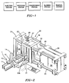
- Figure 1 shows in a block diagram the preferred cycle from injection station where the parisons or preforms are prepared, to receiving station where they are transferred to holding means including mandrels, preferably by a robot, to a temperature conditioning station where the temperature is adjusted so as to be suitable for blowing and biaxial orientation, to the blowing station, and finally to the blown article removal station.
- the cycle is shown in U.S. Patent No. 4,690,633.
- the particular features of the overall cycle are not critical to the present invention. Thus, one can readily use an apparatus as shown and described in U.S. Patent No. 4,690,633.
- the parisons may or may not be prepared in-line with the other operations and may readily be made at a different time.
- the transfer path may take the form of an oval path, a straight path, or a horse-shoe shaped path, or any convenient configuration.
- the apparatus of the present invention is directed to the blow molding station and particularly to an apparatus for releasing the air trapped in the mold cavity upon expansion of the parison therein.
- Figure 2 is an isometric schematic view of a representative blow molding station including the holding means with parison thereon aligned and ready to be received by the blow mold.
- Figure 2 shows a single holding means carrying a single parison; however, it should be understood that the present invention may readily be used when the holding means carries a plurality of parisons or when a plurality of mandrels carry a plurality of parisons.
- the present invention has been described with a single holding means carrying a single parison.
- holding means 1 includes pallets 10 retained in channel track 11 having been transferred thereto from the conditioning station by means not shown.
- Pallets 10 hold rotatable mandrels 12 which in turn hold parisons or preforms 14.
- the particular parison shape is representative only and any suitable shape can be used.
- the parison and mandrel arrives at the blow station after traversing a conditioning station on a rotating mandrel as described in the aforesaid U.S. Patent 4,690,633.
- Blow mold 20 includes fixed first platen 21 and movable second platen 22, fixed first mold portion 23 and movable second mold portion 23A forming therebetween a mold cavity 24 in the shape of the hollow article to be formed.
- Movable platen 22 moves on tie rods 25 activated by motor 26.
- Base mold 27, if used, is positioned above mold 24 to form the article bottom with piston 28 connected thereto for moving the bottom mold into appropriate alignment for formation of the desired base for the article and motive means (not shown) connected thereto for activating said piston.
- both platens and mold portions may be movable, but the present invention also contemplates one being fixed as shown in Figure 2.
- Linkage means 29 are provided connected to the movable platen 22 and bottom mold 27 in order to maintain the desired positioning thereof.
- top linkage means are shown in Figure 2.
- Channel track 30 sits spaced from but closely adjacent to channel track 11 so that pallets 10 can readily move into position in the blow mold.
- the holding means may include a depending leg or spindle or other means which may be engaged by a chain link or any other desired motive means for moving the pallet.
- Means 31 are also provided for introducing high pressure fluid from a fluid source (not shown) into the parison in the mold cavity to expand the parison into conformity with the mold cavity.
- a stretch rod may also be provided for introduction into the parison as is known in the art to provide a stretch blow molded article.
- the present invention utilizes a spacing means, as a spacing bar, which contacts the platens and which is operative to space apart the mold portions in the closed position thereof to form a controlled vent therebetween. This is clearly shown in Figures 3-4.
- Figure 3 shows blow mold 40 in the closed position and Figure 4 shows the blow mold in the open position.
- Mold portions 41 and 42 are affixed to platens 43 and 44, respectively, as for example by bolting, and in the mold closed position of Figure 3 form mold cavity 45 therebetween having a shape of a desired article.
- the platens and mold portions affixed thereto are relatively reciprocable from mold open to closed to open positions via motive means (not shown).
- both platens and mold portions may be movable, or if desired one may be fixed.
- Mold portions 41 and 42 are preferably spaced apart by spacing means or spacing bar 46 affixed to platen 44 so that when platens 43 and 44 move, mold portions 41 and 42 from the mold open to the mold closed position, spacing means 46 contacts both platens 43 and 44 and forms a controlled, predetermined vent 47 between the mold portions, preventing the mold portions from contacting each other at the position of the controlled vent.
- spacing means or spacing bar 46 may be provided to space apart the mold portions in the closed position thereof to form the controlled vent.
- Mandrel locking means 50 and 51 are each mounted to a respective platen 43 and 44 beneath mold portions 41 and 42, also acting as a shelf onto which the two mold halves are placed. This facilitates changing the mold.
- the mandrel locking means 51 and 52 include space 53 therebetween adjacent mold cavity 45 to accommodate a parison holding means or pallet.
- the mandrel locking means also serve lower mold spacing means to control the mold portions in the closed position.
- the spacing means 46 may be affixed to one of the platens as shown or linked thereto, or if desired affixed to the machine frame, or connected in any other suitable way.
- a continuous gap 47 is conveniently and expeditiously formed between the mold halves of desired dimension and without stress on moving parts. This readily allows venting of the air trapped between the inside cavity shape and the rapidly expanding preform during blowing. Moreover, in accordance with the apparatus of the present invention, the controlled vent remains uniform during repeated cycles. Means are provided above and below the mold portions to accurately and consistently provide the desired configuration and space apart the platens in the mold closed position. A predetermined space is formed between the mold faces to enable efficient venting. These two mold surfaces never contact each other and consequently do not wear or become damaged as is the case in conventional molding systems.
- a bottom mold insert 60 can be connected to the spacing bar as shown in Figures 5-6 wherein spacing bar 46 is connected to moving platens 43 and 44.
- Two sets of pivot bearings 61 are each mounted on the ends of bar 46 and platens 43 and 44. Links 62 connect the respective bearings such that when the platens move toward each other the spacing bar 46 is lowered toward the mold 45 and when the platens are moved apart bar 46 is raised away from the mold 45.
- bar 46 is used as a mounting platform for an optional mold insert 60, which is desirably a round plug, to form a recess in the base of the blown article.
- an optional mold insert 60 which is desirably a round plug, to form a recess in the base of the blown article.
- the controlled vent would desirably be on either side of the insert in the seated position shown in Figure 5.
- the vertical motion of bar 46 is required in order to extract insert 60 from the blown article before the article (still on its pallet) can be transported out of the mold area.
Landscapes
- Engineering & Computer Science (AREA)
- Mechanical Engineering (AREA)
- Manufacturing & Machinery (AREA)
- Blow-Moulding Or Thermoforming Of Plastics Or The Like (AREA)
- Moulds For Moulding Plastics Or The Like (AREA)
Applications Claiming Priority (2)
| Application Number | Priority Date | Filing Date | Title |
|---|---|---|---|
| US979892 | 1992-11-23 | ||
| US07/979,892 US5240402A (en) | 1992-11-23 | 1992-11-23 | Apparatus for preparing hollow plastic article |
Publications (1)
| Publication Number | Publication Date |
|---|---|
| EP0599778A1 true EP0599778A1 (de) | 1994-06-01 |
Family
ID=25527203
Family Applications (1)
| Application Number | Title | Priority Date | Filing Date |
|---|---|---|---|
| EP93810419A Ceased EP0599778A1 (de) | 1992-11-23 | 1993-06-11 | Vorrichtung zum Herstellen von Kunststoffrohrkörpern |
Country Status (3)
| Country | Link |
|---|---|
| US (1) | US5240402A (de) |
| EP (1) | EP0599778A1 (de) |
| JP (1) | JPH06198725A (de) |
Cited By (1)
| Publication number | Priority date | Publication date | Assignee | Title |
|---|---|---|---|---|
| FR2841495A1 (fr) * | 2002-06-27 | 2004-01-02 | Sidel Sa | Dispositif de moulage, par soufflage ou etirage-soufflage, de recipients en matiere thermoplastique |
Families Citing this family (7)
| Publication number | Priority date | Publication date | Assignee | Title |
|---|---|---|---|---|
| US6929462B1 (en) | 2000-11-08 | 2005-08-16 | Hammonton Mold Co. Inc. | Mold part guide mechanism |
| US20040151611A1 (en) * | 2003-01-30 | 2004-08-05 | Kline Kerry J. | Method for producing powder metal tooling, mold cavity member |
| US20050040566A1 (en) * | 2003-08-22 | 2005-02-24 | Harald Knueppel | Method and apparatus for blow molding |
| FR2874350B1 (fr) * | 2004-08-18 | 2007-12-21 | Faurecia Interieur Ind Snc | Moule pour moulage par injection d'une piece en matiere plastique et procede de moulage |
| US7854876B2 (en) | 2007-05-25 | 2010-12-21 | Ecovision Technologies, Llc | Apparatus and methods for modular preform mold system |
| FR2947755B1 (fr) * | 2009-07-08 | 2011-07-22 | Comep | Moule perfectionne notamment pour fond de bouteille en matiere plastique et son procede de realisation |
| CH703721A1 (de) * | 2010-09-14 | 2012-03-15 | Alpla Werke | Blasformwerkzeug mit einem abhebbaren Formteil. |
Family Cites Families (12)
| Publication number | Priority date | Publication date | Assignee | Title |
|---|---|---|---|---|
| NL84643C (de) * | 1954-06-29 | |||
| US3078508A (en) * | 1961-04-26 | 1963-02-26 | Hoover Ball & Bearing Co | Method and apparatus for blow molding hollow articles |
| JPS4860707A (de) * | 1971-12-02 | 1973-08-25 | ||
| DE2545130C3 (de) * | 1975-10-08 | 1980-06-26 | Gildemeister Corpoplast Gmbh, 2000 Hamburg | Vorrichtung zum Blasformen eines Behälters |
| US4140468A (en) * | 1977-06-13 | 1979-02-20 | Emhart Industries, Inc. | Plastic bottle forming machine with modular design |
| AU529914B2 (en) * | 1980-11-20 | 1983-06-23 | Ube Industries, Ltd. | Gas venting incorporated with a mould |
| US4421472A (en) * | 1981-08-31 | 1983-12-20 | R & B Machine Tool Company | Clamp for blow molding machine |
| US4648831A (en) * | 1984-03-28 | 1987-03-10 | Owens-Illinois, Inc. | Blow molding apparatus |
| US4690633A (en) * | 1984-09-07 | 1987-09-01 | Husky Injection Molding Systems Ltd. | Apparatus for preparing hollow plastic articles |
| US4793960A (en) * | 1985-05-14 | 1988-12-27 | Husky Injection Molding Systems Ltd. | Process for preparing hollow plastic articles |
| JPH02220757A (ja) * | 1989-02-20 | 1990-09-03 | Mazda Motor Corp | 成形型用ガス抜き装置 |
| JP3047481B2 (ja) * | 1991-03-05 | 2000-05-29 | 凸版印刷株式会社 | Petボトルの製造方法 |
-
1992
- 1992-11-23 US US07/979,892 patent/US5240402A/en not_active Expired - Fee Related
-
1993
- 1993-06-11 EP EP93810419A patent/EP0599778A1/de not_active Ceased
- 1993-06-14 JP JP5141707A patent/JPH06198725A/ja active Pending
Non-Patent Citations (1)
| Title |
|---|
| D. V. ROSATO: "blow molding handbook", 1989, HANSER VERLAG, MUNICH, 197610 * |
Cited By (3)
| Publication number | Priority date | Publication date | Assignee | Title |
|---|---|---|---|---|
| FR2841495A1 (fr) * | 2002-06-27 | 2004-01-02 | Sidel Sa | Dispositif de moulage, par soufflage ou etirage-soufflage, de recipients en matiere thermoplastique |
| WO2004002716A1 (fr) * | 2002-06-27 | 2004-01-08 | Sidel | Dispositif de moulage, par soufflage ou etirage-soufflage, de recipients en matiere thermoplastique |
| US7241130B2 (en) | 2002-06-27 | 2007-07-10 | Sidel | Device for blow-molding or stretch blow molding of thermoplastic containers |
Also Published As
| Publication number | Publication date |
|---|---|
| US5240402A (en) | 1993-08-31 |
| JPH06198725A (ja) | 1994-07-19 |
Similar Documents
| Publication | Publication Date | Title |
|---|---|---|
| US5238389A (en) | Apparatus for preparing a hollow plastic article | |
| EP0266804B1 (de) | Herstellung von hohlen Kunststoffartikeln | |
| EP0001626B1 (de) | Spritzblas-Vorrichtung und -Verfahren | |
| US4376090A (en) | Injection molding system | |
| JP2780367B2 (ja) | プラスチックボトルの製造装置及び製造方法 | |
| JPH09507178A (ja) | 熱可塑性容器、特にボトルを製造するための方法および装置 | |
| EP0086385B1 (de) | Verfahren und Vorrichtung zum Formgebung | |
| US3978184A (en) | Method of two-step blow molding employing a transfer clamp | |
| US4375947A (en) | Injection molding system | |
| US5240402A (en) | Apparatus for preparing hollow plastic article | |
| GB2293344A (en) | Cooling injection and blow moulded parisons | |
| JPH0679773A (ja) | 射出延伸吹込成形方法及び装置 | |
| US5169705A (en) | Servo electric driven stretch rods for blow molding machine | |
| US6358038B1 (en) | Injection stretch blow molding machine | |
| CA1048219A (en) | Method of and apparatus for blow molding plastic articles | |
| EP0228106B1 (de) | Verfahren zum Formen von hohlen Behältern aus molekular orientierbarem Kunststoff | |
| US4308086A (en) | Apparatus for the preparation of hollow plastic articles with a base cup | |
| EP0499136A2 (de) | Servo-elektrisch angetriebener Reckstab für Blasformmaschine | |
| US5112561A (en) | Blow-molding methods for fabricating hollow articles from an open-ended tubular body of thermoplastic material | |
| US5340302A (en) | Apparatus for preparing hollow plastic article | |
| US4207134A (en) | Apparatus for the preparation of hollow plastic articles | |
| CA1176415A (en) | Clamp device for molds used in the blow molding of hollow plastic articles | |
| US5137443A (en) | Apparatus for forming hollow plastic article | |
| US4234302A (en) | Apparatus for the preparation of hollow plastic articles | |
| US4230298A (en) | Apparatus for the preparation of hollow plastic articles |
Legal Events
| Date | Code | Title | Description |
|---|---|---|---|
| PUAI | Public reference made under article 153(3) epc to a published international application that has entered the european phase |
Free format text: ORIGINAL CODE: 0009012 |
|
| 17P | Request for examination filed |
Effective date: 19940122 |
|
| AK | Designated contracting states |
Kind code of ref document: A1 Designated state(s): AT BE CH DE DK ES FR GB GR IE IT LI LU NL PT SE |
|
| 17Q | First examination report despatched |
Effective date: 19951113 |
|
| GRAG | Despatch of communication of intention to grant |
Free format text: ORIGINAL CODE: EPIDOS AGRA |
|
| STAA | Information on the status of an ep patent application or granted ep patent |
Free format text: STATUS: THE APPLICATION HAS BEEN REFUSED |
|
| 18R | Application refused |
Effective date: 19970126 |