EP0600129A1 - Sattdampfdiffusor mit Kondensationsteilen - Google Patents
Sattdampfdiffusor mit Kondensationsteilen Download PDFInfo
- Publication number
- EP0600129A1 EP0600129A1 EP92310890A EP92310890A EP0600129A1 EP 0600129 A1 EP0600129 A1 EP 0600129A1 EP 92310890 A EP92310890 A EP 92310890A EP 92310890 A EP92310890 A EP 92310890A EP 0600129 A1 EP0600129 A1 EP 0600129A1
- Authority
- EP
- European Patent Office
- Prior art keywords
- flow
- vapor
- diffuser
- interface
- water
- Prior art date
- Legal status (The legal status is an assumption and is not a legal conclusion. Google has not performed a legal analysis and makes no representation as to the accuracy of the status listed.)
- Withdrawn
Links
Images
Classifications
-
- F—MECHANICAL ENGINEERING; LIGHTING; HEATING; WEAPONS; BLASTING
- F01—MACHINES OR ENGINES IN GENERAL; ENGINE PLANTS IN GENERAL; STEAM ENGINES
- F01D—NON-POSITIVE DISPLACEMENT MACHINES OR ENGINES, e.g. STEAM TURBINES
- F01D25/00—Component parts, details, or accessories, not provided for in, or of interest apart from, other groups
- F01D25/30—Exhaust heads, chambers, or the like
-
- F—MECHANICAL ENGINEERING; LIGHTING; HEATING; WEAPONS; BLASTING
- F01—MACHINES OR ENGINES IN GENERAL; ENGINE PLANTS IN GENERAL; STEAM ENGINES
- F01D—NON-POSITIVE DISPLACEMENT MACHINES OR ENGINES, e.g. STEAM TURBINES
- F01D25/00—Component parts, details, or accessories, not provided for in, or of interest apart from, other groups
- F01D25/08—Cooling; Heating; Heat-insulation
- F01D25/14—Casings modified therefor
-
- F—MECHANICAL ENGINEERING; LIGHTING; HEATING; WEAPONS; BLASTING
- F05—INDEXING SCHEMES RELATING TO ENGINES OR PUMPS IN VARIOUS SUBCLASSES OF CLASSES F01-F04
- F05D—INDEXING SCHEME FOR ASPECTS RELATING TO NON-POSITIVE-DISPLACEMENT MACHINES OR ENGINES, GAS-TURBINES OR JET-PROPULSION PLANTS
- F05D2260/00—Function
- F05D2260/20—Heat transfer, e.g. cooling
Definitions
- This invention applies to saturated vapor passages where high velocity conditions can be advantageously slowed by means of a flow diffuser that simultaneously causes the static pressure to rise as vapor velocity is decreased by increasing the flow area.
- An ideal diffuser would reversibly convert the high initial kinetic energy to potential energy, thus increasing the static pressure.
- Diffusers for example, are commonly employed in steam turbines. Effective diffusers can improve turbine efficiency and output. Unfortunately, the complicated flow patterns existing in such turbines as well as the design problems caused by space limiations make fully effective diffusers almost impossible to design. A frequent result is flow separation that fully or partially destroys the ability of the diffuser to raise the static pressure as the steam velocity is reduced by increasing the flow area. This is often caused by a vapor boundary layer that gets thicker along the diffuser surface in the direction of flow ultimately permitting the flow separation mentioned above.
- the turbine shaft and last stage rotating blades rotate at high speed, often at 3600 rpm, with over 1800 feet per second top speed.
- the limit occurs when the axial steam velocity in the annular space immediately downstream from the last stage rotating blade equals sonic velocity. This is typically about 1220 feet per second for wet steam at the discharge of the low pressure turbine. Any further dropping of static pressure below this condition will not result in increased output and may in fact, slightly reduce output.
- the condenser hotwell pressure is essentially established by the condenser tube geometry, the temperature of the circulating water, and the heat to be removed from the steam exhausted from the turbine.
- the static pressure of the steam exiting the exhaust hood and entering the condenser is usually close to the pressure existing in the hotwell, depending on local flow interferences such as pipes and side wall obstructions and feed water heaters. It should be recognized that if there are significant interferences, the pressure at the discharge of the exhaust hood will be higher than the hotwell.
- the static pressure at the discharge side of the diffuser will be higher than that of the exhaust hood discharge by the amount of pressure drop required to turn the flow from nearly axial to vertical and by the necessary pressure drop caused by passage of pipes, struts, and other such interferences.
- the static pressure at the annulus immediately downstream of the last stage rotating blade will be lower than that at the discharge of the diffuser by the amount of successful diffusion, that is, the degree to which the reduced average velocity has been successfully turned into higher static pressure as the steam flows along the diffusing path.
- the present invention comprises a system and means to cause the walls of a diffuser and bearing cone to be colder than the saturation temperature of the vapor being diffused. This results in portions of the boundary layer of the flow, which are in direct contact with the diffuser and bearing cone cold walls, to become condensed, preventing the boundary layer from becoming excessively thick as it flows along the diffuser and bearing cone surfaces, such thickening being one of the major causes of flow separation.
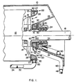
- Fig. 1 depicts a typical arrangement of a low pressure turbine of which only one end of a double flow unit is shown.
- An exhaust hood 10 surrounds an inner casing 12, which in turn, encloses and supports the stationary parts of the low pressure stages such as a last stage diaphragm 14.
- a turbine rotor 16 is turned by the force of high velocity steam which is directed against rotating blades 18 which are mounted in a full circle around the rotor. Only the last stage of the low pressure turbine is shown but it will be recognized that most low pressure turbines will include about six stages per end, although more and less would also be common.
- a diffuser 20 is securely mounted on inner casing 12 adjacent the last stage rotating blade 18.
- a bearing cone 22 supports packing rings 24 that separate the vacuum condition that exists inside exhaust hood 10 from atmospheric pressure on the outside.
- Bearing cone 22 in combination with a surface 40 to be described, also provide the inner surface diffusing flow path of steam exiting the last stage bucket in the direction of the arrows A. After leaving the diffusing path the steam must be turned downward to enter a condenser, not shown, mounted directly on the bottom of the exhaust hood.
- a hotwell also not shown, is at the bottom of the condenser. Additionally not shown are the bearings which support the shaft and which would often be mounted in the bearing cone 22.
- Diffuser 20 includes walls 25, 26 and 27 which define an internal annular cooling passage or water circulating space 28 which persists for the full 360 o of the diffuser except at the diffuser base where a divider or partition wall 30 extends across passage 28.
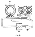
- Cold water is delivered to circulating space 28 by an inlet pipe 32 and exits from space 28 as somewhat warmed water through an exit pipe 34 located adjacent pipe 32, (see Fig. 2), with divider or partition wall 30 precluding any mingling of the cold entry water with the warmed exit water.
- Dual cooling means are provided for bearing cone 22 and include first and second cold water ducts 42 and 52 respectively, mounted within the bearing cone.
- First cold water duct 42 includes walls 40 and 41 which define an internal annular cooling passage or water circulating space 42 which persists for the full 360 o of the bearing cone except at the duct base where a divider or partition wall 44 extends across space 42.
- Cold water is delivered to circulating space 42 by an inlet pipe 46 and exits from space 42 as somewhat warmed water through an exit pipe 48 located adjacent pipe 46, (see Fig. 2), with divider or partition wall 44 precluding any mingling of the cold entry water with the warmed exit water.
- Second cold water duct 52 includes an outer wall of bearing cone 22 and inner walls 50 which define an internal annular cooling passage or water circulating space 52 which persists for the full 360 o of the bearing cone except at the duct base where a divider or partition wall 54 extends across space 52.
- Cold water is delivered to circulating space 52 by an inlet pipe 56 and exits from space 52 as somewhat warmed water through an exit pipe 58 located adjacent pipe 56, (see Fig. 2), with divider or partition wall 54 precluding any mingling of the cold entry water with the warmed exit water.
- pipes and ducts are insulated from warmer fluids by such methods as metal lagging as shown in areas indicated by 60.
- support equipment includes a pump 62, which circulates cold water through the pipe and duct system and a water cooler or chiller 64 to cool the water.
- Orifices 66 are used in each inlet pipe 32, 46 and 56 to insure the proper split and magnitude of cooling flow.
- the condensate flow could be the source of make up water for the cooling system.
- cool water is circulated so as to cool wall surface 26 of diffuser 20, wall surface 40 of duct 42 and cone surface 22 of duct 52 in the flow path A of steam exiting the last stage bucket.
- the water should be of sufficient quantity to assure condensing a small amount of the steam passing in contact with those surfaces. Up to 1% of the steam could be considered a desirable amount.
- the amount of condensation should be enough to keep flow boundary layers thin.
- the cool water should flow in sufficient quantity to pick up approximately 10 to 20 o in temperature and always be about 10 o F lower than the steam saturation temperature.
- a variety of systems could be considered to obtain water about 20 o F cooler than the saturation temperature of exhausting steam. These could include the ordinary circulating water which sometimes may be about that temperature. Sometimes makeup water to the turbine feed-water system may be the proper temperature and amount. A special cooler may be needed to create the right temperature and flow rate. A heat pump could also be used with a variety of heat rejection media including ambient air, ground water or circulating water.
- Non-water cooling is also possible using other fluids or refrigerants.
- the condensation function of the cooled diffuser and duct surfaces can benefit from a wall that has a minimum resistance to heat flow. To that end the wall should be thin or of high conductivity. It is recognized that in the turbine example, the outer diffuser and duct walls will be exposed to high velocity water droplets that are known to erode materials such as carbon steel. A harder or better protected surface will be required in such areas.
- the diffuser surface could be perforated or slotted so that suction applied to the hollow diffuser wall could continuously draw boundary layer flow away to accomplish the same effect provided by the condensation systems described earlier.
- duct 42 is made separate from duct 52 and is bolted to the lower half.
- duct 42 remains in place and the part of the bearing cone that rises is short enough to avoid contact with diffuser 20.
- the same effect could be accomplished by having a portion of diffuser 20 removable so that it would permit the entire bearing cone to be lifted vertically. In such a case, ducts 42 and 52 could be combined into one duct.
- the combined axial length of the chilled surfaces provided by ducts 42 and 52 need only be long enough to insure that the steam flow is fully in contact with the bearing cone surface and that the increased wall static pressure caused by turning the flow is great enough to insure against flow separation.
- the improved system and apparatus of the invention affords an efficient and effective way of increasing diffuser effectiveness and turbine performance.
Landscapes
- Engineering & Computer Science (AREA)
- Mechanical Engineering (AREA)
- General Engineering & Computer Science (AREA)
- Engine Equipment That Uses Special Cycles (AREA)
- Control Of Turbines (AREA)
Priority Applications (2)
| Application Number | Priority Date | Filing Date | Title |
|---|---|---|---|
| US07/819,879 US5167123A (en) | 1992-01-13 | 1992-01-13 | Flow condensing diffusers for saturated vapor applications |
| EP92310890A EP0600129A1 (de) | 1992-01-13 | 1992-11-30 | Sattdampfdiffusor mit Kondensationsteilen |
Applications Claiming Priority (2)
| Application Number | Priority Date | Filing Date | Title |
|---|---|---|---|
| US07/819,879 US5167123A (en) | 1992-01-13 | 1992-01-13 | Flow condensing diffusers for saturated vapor applications |
| EP92310890A EP0600129A1 (de) | 1992-01-13 | 1992-11-30 | Sattdampfdiffusor mit Kondensationsteilen |
Publications (1)
| Publication Number | Publication Date |
|---|---|
| EP0600129A1 true EP0600129A1 (de) | 1994-06-08 |
Family
ID=26132281
Family Applications (1)
| Application Number | Title | Priority Date | Filing Date |
|---|---|---|---|
| EP92310890A Withdrawn EP0600129A1 (de) | 1992-01-13 | 1992-11-30 | Sattdampfdiffusor mit Kondensationsteilen |
Country Status (2)
| Country | Link |
|---|---|
| US (1) | US5167123A (de) |
| EP (1) | EP0600129A1 (de) |
Cited By (2)
| Publication number | Priority date | Publication date | Assignee | Title |
|---|---|---|---|---|
| EP0838595A3 (de) * | 1996-10-23 | 1998-11-25 | Asea Brown Boveri AG | Schaufelträger für einen Verdichter |
| EP1655458A1 (de) * | 2004-11-04 | 2006-05-10 | Siemens Aktiengesellschaft | Diffusor für Dampfturbine |
Families Citing this family (8)
| Publication number | Priority date | Publication date | Assignee | Title |
|---|---|---|---|---|
| IL121546A (en) * | 1997-08-14 | 2003-07-06 | Arie Raz | Compression and condensation of turbine exhaust steam |
| US6484503B1 (en) | 2000-01-12 | 2002-11-26 | Arie Raz | Compression and condensation of turbine exhaust steam |
| US8161749B2 (en) | 2009-04-07 | 2012-04-24 | General Electric Company | Cooled exhaust hood plates for reduced exhaust loss |
| US8221054B2 (en) * | 2009-05-28 | 2012-07-17 | General Electric Company | Corrugated hood for low pressure steam turbine |
| US8221053B2 (en) * | 2009-05-28 | 2012-07-17 | General Electric Company | Shaped and stiffened lower exhaust hood sidewalls |
| US8439633B2 (en) * | 2010-01-04 | 2013-05-14 | General Electric Company | Hollow steam guide diffuser having increased pressure recovery |
| US10392968B2 (en) * | 2017-04-24 | 2019-08-27 | United Technologies Corporation | Turbine casing cooling structure |
| US10794225B2 (en) * | 2018-03-16 | 2020-10-06 | Uop Llc | Turbine with supersonic separation |
Citations (6)
| Publication number | Priority date | Publication date | Assignee | Title |
|---|---|---|---|---|
| FR488782A (fr) * | 1918-02-04 | 1918-11-14 | Albert Delas | Éjecteur à vapeur |
| FR491620A (fr) * | 1918-09-06 | 1919-06-10 | Albert Delas | Éjecteur à vapeur à diffuseur refroidi et son application à un système à condenseur intermédiaire |
| GB291374A (en) * | 1927-05-31 | 1928-09-06 | Francois Xavier Joseph Albert | Method and device for increasing the speed and output of a fluid current chiefly in steam turbines |
| US1688413A (en) * | 1919-11-22 | 1928-10-23 | Delas Condenser Corp | Method of and apparatus for increasing the vacuum of turbines |
| DE907180C (de) * | 1951-03-08 | 1954-03-22 | Rolf Roeder Dipl Ing | Auslassdiffusor kurzer Baulaenge fuer Dampfturbinen |
| DE1054791B (de) * | 1954-11-11 | 1959-04-09 | Licentia Gmbh | Grenzschichtabsaugungseinrichtung fuer von einem kondensierbaren Dampf bestroemte Waende |
Family Cites Families (10)
| Publication number | Priority date | Publication date | Assignee | Title |
|---|---|---|---|---|
| US1091581A (en) * | 1911-02-24 | 1914-03-31 | Ljungstroems Angturbin Ab | Diffuser for steam turbines, compressors, pumps, blasts, and the like. |
| US1131645A (en) * | 1914-02-07 | 1915-03-09 | Charles Volney Kerr | Exhaust for steam-turbines. |
| US1269998A (en) * | 1915-02-01 | 1918-06-18 | Westinghouse Electric & Mfg Co | Steam-turbine. |
| US2810545A (en) * | 1947-07-31 | 1957-10-22 | Buchi Alfred | Diffusers |
| US2762560A (en) * | 1950-09-02 | 1956-09-11 | Burmeister & Wains Mot Mask | Diffuser for the conversion of kinetic energy into pressure energy and axialflow engine provided with such a diffuser |
| US3306575A (en) * | 1964-03-05 | 1967-02-28 | Ass Elect Ind | Steam turbines |
| US3338052A (en) * | 1965-10-22 | 1967-08-29 | Westinghouse Electric Corp | High recovery condenser |
| US3498062A (en) * | 1966-08-24 | 1970-03-03 | English Electric Co Ltd | Turbine plant |
| FR2401311A1 (fr) * | 1977-08-25 | 1979-03-23 | Europ Turb Vapeur | Dispositif d'echappement pour turbine axiale a fluide condensable |
| DE3627306A1 (de) * | 1986-02-28 | 1987-09-03 | Mtu Muenchen Gmbh | Einrichtung zur belueftung von rotorbauteilen fuer verdichter von gasturbinentriebwerken |
-
1992
- 1992-01-13 US US07/819,879 patent/US5167123A/en not_active Expired - Fee Related
- 1992-11-30 EP EP92310890A patent/EP0600129A1/de not_active Withdrawn
Patent Citations (6)
| Publication number | Priority date | Publication date | Assignee | Title |
|---|---|---|---|---|
| FR488782A (fr) * | 1918-02-04 | 1918-11-14 | Albert Delas | Éjecteur à vapeur |
| FR491620A (fr) * | 1918-09-06 | 1919-06-10 | Albert Delas | Éjecteur à vapeur à diffuseur refroidi et son application à un système à condenseur intermédiaire |
| US1688413A (en) * | 1919-11-22 | 1928-10-23 | Delas Condenser Corp | Method of and apparatus for increasing the vacuum of turbines |
| GB291374A (en) * | 1927-05-31 | 1928-09-06 | Francois Xavier Joseph Albert | Method and device for increasing the speed and output of a fluid current chiefly in steam turbines |
| DE907180C (de) * | 1951-03-08 | 1954-03-22 | Rolf Roeder Dipl Ing | Auslassdiffusor kurzer Baulaenge fuer Dampfturbinen |
| DE1054791B (de) * | 1954-11-11 | 1959-04-09 | Licentia Gmbh | Grenzschichtabsaugungseinrichtung fuer von einem kondensierbaren Dampf bestroemte Waende |
Cited By (2)
| Publication number | Priority date | Publication date | Assignee | Title |
|---|---|---|---|---|
| EP0838595A3 (de) * | 1996-10-23 | 1998-11-25 | Asea Brown Boveri AG | Schaufelträger für einen Verdichter |
| EP1655458A1 (de) * | 2004-11-04 | 2006-05-10 | Siemens Aktiengesellschaft | Diffusor für Dampfturbine |
Also Published As
| Publication number | Publication date |
|---|---|
| US5167123A (en) | 1992-12-01 |
Similar Documents
| Publication | Publication Date | Title |
|---|---|---|
| US5494413A (en) | High speed fluid pump powered by an integral canned electrical motor | |
| EP0704603A2 (de) | Verfahren und Vorrichtung zur Wellendichtung und zur Kühlung auf der Abgasseite einer axialdurchströmten Gasturbine | |
| EP0298011B1 (de) | In einer Rotorkappe montiertes Schmier- und Kühlsystem | |
| JPH0281930A (ja) | ターボエンジン | |
| RU2472946C2 (ru) | Устройство для отбора энергии из потока сжатого газа | |
| US7455150B1 (en) | Rotating shaft scavenging scoop | |
| CN1043679C (zh) | 从轴承装置中排出润滑剂的装置 | |
| US5167123A (en) | Flow condensing diffusers for saturated vapor applications | |
| JPH08218812A (ja) | ターボ機関のころがり軸受の自動潤滑のための方法と装置 | |
| JPH04224234A (ja) | 軸流式のガスタービン | |
| US3424234A (en) | Rotary heat exchangers | |
| US8157512B2 (en) | Heat pipe intercooler for a turbomachine | |
| KR960001439A (ko) | 저온성 정류장치에 사용되는 팽창 터어빈 | |
| KR19980019177A (ko) | 가스 터빈 엔진의 베이링 격실 실 및 액체 밀봉장치(gas turbine engine bearing compartment seal) | |
| US5215429A (en) | Regenerative turbine having predetermined clearance relationship between channel ring and impeller | |
| JP2021167600A (ja) | タービンシャフト継手を冷却するためのシステム | |
| KR20000048758A (ko) | 증기 터빈 및 환기 작업 시 증기 터빈을 냉각하는 방법 | |
| CN116006513A (zh) | 离心式水蒸气压缩机 | |
| US5967743A (en) | Blade carrier for a compressor | |
| US4695223A (en) | Turbomolecular vacuum pump with a rotor and at least one antifriction bearing | |
| EP2239426A2 (de) | Gekühltes Abgasgehäuse einer Dampfturbine | |
| JP2003515690A (ja) | タービン機械のロータとステータとの間に形成された半径方向間隙における流れを冷却するための方法及び装置 | |
| US3933008A (en) | Multistage heat exchanger | |
| PL78278B1 (de) | ||
| US6835044B2 (en) | Draining and cooling system for gas turbine cushions |
Legal Events
| Date | Code | Title | Description |
|---|---|---|---|
| PUAI | Public reference made under article 153(3) epc to a published international application that has entered the european phase |
Free format text: ORIGINAL CODE: 0009012 |
|
| AK | Designated contracting states |
Kind code of ref document: A1 Designated state(s): CH DE FR GB IT LI SE |
|
| 18D | Application deemed to be withdrawn |
Effective date: 19941209 |