EP0600145B1 - Sportschuhe - Google Patents
Sportschuhe Download PDFInfo
- Publication number
- EP0600145B1 EP0600145B1 EP93101367A EP93101367A EP0600145B1 EP 0600145 B1 EP0600145 B1 EP 0600145B1 EP 93101367 A EP93101367 A EP 93101367A EP 93101367 A EP93101367 A EP 93101367A EP 0600145 B1 EP0600145 B1 EP 0600145B1
- Authority
- EP
- European Patent Office
- Prior art keywords
- walking
- degrees
- angle
- sole
- sole portion
- Prior art date
- Legal status (The legal status is an assumption and is not a legal conclusion. Google has not performed a legal analysis and makes no representation as to the accuracy of the status listed.)
- Revoked
Links
- 230000008878 coupling Effects 0.000 claims description 2
- 238000010168 coupling process Methods 0.000 claims description 2
- 238000005859 coupling reaction Methods 0.000 claims description 2
- 210000003371 toe Anatomy 0.000 description 56
- 210000002683 foot Anatomy 0.000 description 46
- 210000003205 muscle Anatomy 0.000 description 41
- 210000003127 knee Anatomy 0.000 description 32
- 238000010586 diagram Methods 0.000 description 29
- 230000000694 effects Effects 0.000 description 24
- 210000003423 ankle Anatomy 0.000 description 19
- 238000012549 training Methods 0.000 description 19
- 210000000544 articulatio talocruralis Anatomy 0.000 description 16
- 210000003414 extremity Anatomy 0.000 description 16
- 230000035939 shock Effects 0.000 description 15
- 244000309466 calf Species 0.000 description 14
- 238000002474 experimental method Methods 0.000 description 12
- 230000008859 change Effects 0.000 description 11
- 210000002414 leg Anatomy 0.000 description 11
- 208000007623 Lordosis Diseases 0.000 description 9
- 230000006870 function Effects 0.000 description 8
- 210000004394 hip joint Anatomy 0.000 description 8
- 210000000629 knee joint Anatomy 0.000 description 8
- 208000008035 Back Pain Diseases 0.000 description 7
- 208000008930 Low Back Pain Diseases 0.000 description 7
- 238000005452 bending Methods 0.000 description 6
- 230000006872 improvement Effects 0.000 description 6
- 238000006073 displacement reaction Methods 0.000 description 5
- 210000001503 joint Anatomy 0.000 description 5
- 238000005259 measurement Methods 0.000 description 5
- 210000001872 metatarsal bone Anatomy 0.000 description 5
- 210000000878 metatarsophalangeal joint Anatomy 0.000 description 5
- 235000017166 Bambusa arundinacea Nutrition 0.000 description 4
- 235000017491 Bambusa tulda Nutrition 0.000 description 4
- 241001330002 Bambuseae Species 0.000 description 4
- 235000015334 Phyllostachys viridis Nutrition 0.000 description 4
- 239000011425 bamboo Substances 0.000 description 4
- 230000005484 gravity Effects 0.000 description 4
- 230000003155 kinesthetic effect Effects 0.000 description 4
- 238000010521 absorption reaction Methods 0.000 description 3
- 230000009471 action Effects 0.000 description 3
- 238000012937 correction Methods 0.000 description 3
- 230000003247 decreasing effect Effects 0.000 description 3
- 210000000610 foot bone Anatomy 0.000 description 3
- 230000007246 mechanism Effects 0.000 description 3
- 238000000034 method Methods 0.000 description 3
- 230000002787 reinforcement Effects 0.000 description 3
- 210000001137 tarsal bone Anatomy 0.000 description 3
- 210000000689 upper leg Anatomy 0.000 description 3
- 206010024453 Ligament sprain Diseases 0.000 description 2
- 208000010040 Sprains and Strains Diseases 0.000 description 2
- 239000008280 blood Substances 0.000 description 2
- 210000004369 blood Anatomy 0.000 description 2
- 210000000988 bone and bone Anatomy 0.000 description 2
- 210000001624 hip Anatomy 0.000 description 2
- 230000003014 reinforcing effect Effects 0.000 description 2
- 238000005096 rolling process Methods 0.000 description 2
- 230000035807 sensation Effects 0.000 description 2
- 208000006820 Arthralgia Diseases 0.000 description 1
- 208000025978 Athletic injury Diseases 0.000 description 1
- 208000002193 Pain Diseases 0.000 description 1
- 206010041738 Sports injury Diseases 0.000 description 1
- 208000027418 Wounds and injury Diseases 0.000 description 1
- 210000003489 abdominal muscle Anatomy 0.000 description 1
- 239000010426 asphalt Substances 0.000 description 1
- 230000017531 blood circulation Effects 0.000 description 1
- 230000037396 body weight Effects 0.000 description 1
- 230000009194 climbing Effects 0.000 description 1
- 230000002860 competitive effect Effects 0.000 description 1
- 210000000458 cuboid bone Anatomy 0.000 description 1
- 210000000460 cuneiform bone Anatomy 0.000 description 1
- 230000006378 damage Effects 0.000 description 1
- 230000000994 depressogenic effect Effects 0.000 description 1
- 210000003108 foot joint Anatomy 0.000 description 1
- 208000014674 injury Diseases 0.000 description 1
- 208000024765 knee pain Diseases 0.000 description 1
- 239000010985 leather Substances 0.000 description 1
- 210000003041 ligament Anatomy 0.000 description 1
- 210000003141 lower extremity Anatomy 0.000 description 1
- 230000003387 muscular Effects 0.000 description 1
- 210000000450 navicular bone Anatomy 0.000 description 1
- 210000005036 nerve Anatomy 0.000 description 1
- 210000004197 pelvis Anatomy 0.000 description 1
- 230000002265 prevention Effects 0.000 description 1
- 230000008569 process Effects 0.000 description 1
- 108091008706 proprioceptors Proteins 0.000 description 1
- 210000003314 quadriceps muscle Anatomy 0.000 description 1
- 206010039073 rheumatoid arthritis Diseases 0.000 description 1
- 210000002435 tendon Anatomy 0.000 description 1
- 210000002303 tibia Anatomy 0.000 description 1
- 239000002023 wood Substances 0.000 description 1
Images











Classifications
-
- A—HUMAN NECESSITIES
- A43—FOOTWEAR
- A43B—CHARACTERISTIC FEATURES OF FOOTWEAR; PARTS OF FOOTWEAR
- A43B13/00—Soles; Sole-and-heel integral units
- A43B13/14—Soles; Sole-and-heel integral units characterised by the constructive form
- A43B13/143—Soles; Sole-and-heel integral units characterised by the constructive form provided with wedged, concave or convex end portions, e.g. for improving roll-off of the foot
-
- A—HUMAN NECESSITIES
- A43—FOOTWEAR
- A43B—CHARACTERISTIC FEATURES OF FOOTWEAR; PARTS OF FOOTWEAR
- A43B13/00—Soles; Sole-and-heel integral units
- A43B13/14—Soles; Sole-and-heel integral units characterised by the constructive form
- A43B13/143—Soles; Sole-and-heel integral units characterised by the constructive form provided with wedged, concave or convex end portions, e.g. for improving roll-off of the foot
- A43B13/146—Concave end portions, e.g. with a cavity or cut-out portion
Definitions
- the present invention relates to sports shoes and, more specifically, to sports shoes allowing stretching and reinforcement of muscle strength.
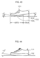
- Fig. 43 is a front view of conventional standard casual shoes
- Fig. 44 is a front view showing conventional standard sports shoes.
- a conventional casual shoe is formed of an instep 101 and a sole 102.
- the sole 102 includes a heel portion 103 and a toe portion 104.
- the heel portion 103 is generally formed to have the height of about 3cm, and a line extending from a lower surface of a ball joint (toe supporting portion) of the wearer to the lower surface of the heel forms an angle of 9 degrees (hereinafter referred to as a toe angle) with the plane of walking.
- the heel portion 103 occupies 31% of the entire area of the sole 102.
- the toe portion 104 has a curved shape, and an angle formed by the tip end portion thereof and the walking plane is generally 13°.
- a conventional sport shoe is formed by an instep 101 and a sole 112.
- the sole 112 has an approximately flat shape and only the tip end portion thereof forms an angle of 10 degrees with the plane of walking.
- Fig. 45 schematically shows configuration of foot bones.
- one's foot is constituted by a number of small bones. More specifically, the bones of one's foot include region phalanges 120, region metatarsal bones 130 and region tarsal bones 140.
- Various joints across the region metatarsal bones and the region tarsal bones 140 are fixed by muscles and ligaments and therefore the joints hardly flex.
- foot joints which bent during walking are the ankle joint, the metatarsophalangeal joint (a joint at the root of the region phalanges, between five metatarsal bones and the proximal phalanges in contact therewith), and a joint at the region phalanges.
- Figs. 46 to 48 are schematic diagrams showing movable range of the ankle joint (ankle).
- movable ranges of planter flexion in which one's foot is bent toward one's calf and of dorsiflexion in which one's foot is bent toward the sole are most important.
- the movable range of the planter flexion is from 0 to 20 degrees and the movable range of the dorsiflexion is from 0 to 40 degrees with one's knee bent, though these ranges, particularly the last 10 degrees much depend on personal differences.
- Fig. 49 is a schematic diagram used for describing the position of the center-of-gravity line of one's body.
- the center-of-gravity line of the body extends from the center-of-gravity of the hip joint, generally passes through the front side of knee joint, and through a position about 2cm in front of the center of one's foot, that is, the ankle.
- the position of the center-of-gravity moves toward one's heels because of fatigue of antigravity muscles, such as erector spinae.
- lumber vertebra bends forward (lordosis) to change one's attitude to relieve burden of antigravity muscles.
- the heel portion 103 of the conventional casual shoes shown in Fig. 43 has influence to the movement of the center-of-gravity toward the heels. More specifically, since the heel portion 103 is a higher position than the toe portion 104 the conventional casual shoes shown in Fig. 43, movement rearward is controlled by utilizing the inclination from the toe portion 104 to heel portion 103, by moving the center-of-gravity to the heel portion 103. In this manner, when one wears the conventional casual shoes shown in Fig. 43 and stands for a long period of time and keeps standing posture for a long period of time, the center-of-gravity moves rearward, causing low-back pain.
- a shoe for supporting directly the foot of a person providing a rigid supporting structure. Therefore a rigid layer of wood or plastic is arranged between a plane of walking and the inner sole of the shoe. The rigid layer and the walking sole do not have a special inclination but a relatively flat form.
- EP 0 049 019 describing a running surface consisting of three flat parts whereby the foremost part is curved upwards from the center part under an angle between 25° and 35° and the hindmost part under an angle between 15° and 25°.
- the purpose of the arrangement of three flat parts is to provide a running surface for approaching a natural movement during the walking process.
- the present invention was made to solve the above described problems and the object of the present invention as stated in claim 1 is to provide sports shoes which effectively prevent low-back pain even when the person wearing the shoes keeps standing posture for a long period of time, which provide effects of reinforcement of muscles and stretching of calves and which improves stability during walking.
- the sports shoes each includes an inner sole formed to be closely in contact with human foot and an outer sole formed to be in contact with the plane of walking.
- the outer sole includes a front sole having a first sole surface supporting the toe portion of one's foot which can be in contact with the plane of walking and a rear sole having a second sole surface supporting the heel portion of one's foot, forming a prescribed angle with the first sole surface and which can be in contact with the plane of walking.
- the inner sole and the front sole are formed such that when the first sole surface is in contact with the plane of walking, a line connecting the lower surface of the toe supporting point and the lower surface of the heel of one's foot forms an angle in the range of 10 to 15 degrees with respect to the plane of walking.
- the front sole and the rear sole are formed such that when at least a portion of the second sole is in contact with the plane of walking, the first sole surface forms an angle in the range from 20 to 25 degrees with respect to the plane of walking.
- the front sole is formed to include a region through which a vertical line including the center-of-gravity of one's body passes and a support point is formed between the front sole portion and the rear sole portion and said support point is formed at a position 30 to 40% of the entire length of said sport shoe from the rear end of the sole portion.
- the inner sole and the front sole are formed such that when the first sole surface of the front sole is in contact with the plane of walking, a line connecting the lower surface of the toe support point of one's foot and the lower surface of the heel forms an angle in the range of 10 to 15 degrees with respect to the plane of walking, and since this angle in the range of 10 to 15 degrees is most suitable for the muscle to fix the movement of the joint as the tension of muscles around the joints are even, stability in standing posture can be obtained.
- the angle of the sole of the kicking foot during walking becomes about 15 degrees with respect to the plane of walking, the area in contact with the ground of the kicking foot is increased as compared with the prior art because of the inclination in the range from 10 to 15 degrees mentioned above, which improves stability in kicking, and strength of muscles are more effectively exhibited.
- the front sole and the rear sole are formed such that when at least a portion of the second sole surface is in contact with the plane of walking, the first sole surface forms an angle in the range from 20 to 25 degrees with the plane of walking, when one wears the sports shoes and brings his or her heel into contact with the plane of walking, the ankle is flexed with the angle in the range of about 7 to about 10 degrees.
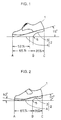
- Fig. 1 is a front view showing the sport shoe in accordance with the first embodiment of the present invention in the toe standing state.
- Fig. 2 is a front view showing the sport shoe in accordance with the first embodiment of the present invention with the toe raised a little.
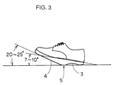
- Fig. 3 is a front view showing the sport shoe in accordance with the first embodiment of the present invention in the heel standing state.
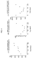
- Fig. 4 shows correlation between the length of body sway of the center-of-gravity (A), the area of body sway of the center-of-gravity (B) and the displacement of the center-of-gravity (C) when the toe angle of one's foot is changed.
- Fig. 5 shows the center-of-gravity when the toe angle is 5 degrees.
- Fig. 6 shows the center-of-gravity when the toe angle is 7 degrees.
- Fig. 7 shows the center-of-gravity when the toe angle is 10 degrees.
- Fig. 8 shows the center-of-gravity when the toe angle is 15 degrees.
- Fig. 9 shows the center-of-gravity when the toe angle is 17 degrees.
- Fig. 10 shows the center-of-gravity when the toe angle is 20 degrees.
- Fig. 11 is a first schematic diagram showing extension of the hip joint.
- Fig. 12 is a second schematic diagram showing the extension of the hip joint.
- Fig. 13 is a diagram for comparison showing the states of ankle joint and knee joint during walking with the walker wearing conventional shoes and the shoes of the first embodiment.
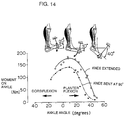
- Fig. 14 shows correlation between the angle of the ankle and the moment (muscle strength exhibited by the calf) applied to the ankle.
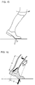
- Fig. 15 is a first schematic diagram explaining the force to flex the knee exerted at the time of kicking during walking.
- Fig. 16 is a schematic diagram explaining force to flex the knee exerted at the time of kicking during walking.
- Fig. 17 shows correlation between the length of body sway of the center-of-gravity (A), the area of body sway of the center-of-gravity (B) and the displacement of gravity (C) when the heel ankle is changed.
- Fig. 18 shows the center-of-gravity when the heel angle is 15 degrees.
- Fig. 19 shows the center-of-gravity when the heel angle is 17 degrees.
- Fig. 20 shows the center-of-gravity when the heel angle is 20 degrees.
- Fig. 21 shows the center-of-gravity when the heel angle is 25 degrees.
- Fig. 22 shows the center-of-gravity when the heel angle is 27 degrees.
- Fig. 23 shows the center-of-gravity when the heel angle is 30 degrees.
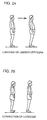
- Fig. 24 is a schematic diagram showing lordosis of lumber vertebra when one keeps standing posture for a long time.
- Fig. 25 is a schematic diagram showing correction of lordosis when the sports shoes of the present invention are used when one keeps standing posture for a long period of time.
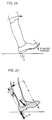
- Fig. 26 is a first schematic diagram for explaining the force of flexing the knee exerted when the heel touches the ground during walking.
- Fig. 27 is a second schematic diagram for explaining the force to flex the knee exerted when the heel touches the ground during walking.
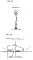
- Fig. 28 shows a concept of the conventional generally known rocker sole.
- Fig. 29 is a front view showing the rocker sole configuration of the sports shoes in accordance with the first embodiment.
- Fig. 30 is an illustration of balance training using a conventional kinesthetic board.
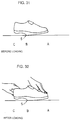
- Fig. 31 is a first front view showing bending of the sports shoes in accordance with the first embodiment.
- Fig. 32 is a second front view showing the bending of the support point of the sport shoe in accordance with the first embodiment.
- Fig. 33 is a schematic diagram showing distribution of shock by an arch configuration of the sport shoe in accordance with the first embodiment of the present invention.
- Fig. 34 is a first front view showing the bent state of the arch configuration of the sport shoe in accordance with the first embodiment.
- Fig. 35 is a second front view showing the bent state of the arch configuration of the sport shoe in accordance with the first embodiment.
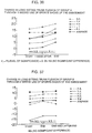
- Fig. 36 is a graph showing the change in long sitting trunk flexion values when a group A used the sports shoes of the present invention for two weeks in a first experiment.
- Fig. 37 is a graph showing the change in the long sitting trunk flexion values when a group B used the sports shoes in accordance with the present embodiment for one week in the first experiment.
- Fig. 38 is a front view of a sport shoe in accordance with the second embodiment of the present invention.
- Fig. 39 is a front view showing a sport shoe in accordance with the third embodiment of the present invention.
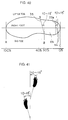
- Fig. 40 is a bottom view showing the shape of the sole of a sport shoe in accordance with the fourth embodiment of the present invention.
- Fig. 41 is a schematic diagram showing the angle of the step of one's foot toward the direction of walking.
- Fig. 42 is a schematic diagram for explaining the movements of inversion and eversion of the foot.
- Fig. 43 is a plan view showing a conventional general casual shoe (leather shoe).
- Fig. 44 is a front view showing a conventional general sport shoe.
- Fig. 45 is a schematic diagram showing structure of foot bones.
- Fig. 46 is a first schematic diagram showing movement of a human foot.
- Fig. 47 is a second schematic diagram showing the movement of one's foot.
- Fig. 48 is a third schematic diagram showing the movement of one's foot.
- Fig. 49 is a schematic diagram showing the position of the line of the center-of-gravity of one's body.
- Figs. 1 to 3 are plan views showing sport shoes in accordance with one embodiment of the present invention.
- the sports shoes of the present invention is each formed of an instep 1 and a sole 2.
- the sole 2 is formed such that a line extending from a lower surface of the toe support point of the person wearing the sports shoes to the lower surface of the heel is inclined by 10 to 15 degrees (toe angle) with respect to the plane of walking when the surface thereof is in contact with the plane of walking, and the area of the toe portion 4 occupies 65% of the entire sole 2.
- the heel portion 3 occupies 35% of the sole 2 and is cut to have an arch. As shown in Fig.
- the ankle joint can be bent rearward (dorsiflexion) by about 7 to 10 degrees, resulting in appropriate stretching of the triceps surae (calf).
- the position of the center-of-gravity of the person wearing the sports shoes passes through a position 52% from the toe. More specifically, when the person wearing the sports shoes takes the toe standing posture as shown in Fig. 1, the line of the center-of-gravity is included in the region of the toe 4, and therefore stability in the standing posture can be obtained even though the heel portion 3 is not in contact with the ground.
- toe angle toe bending angle
- Fig. 4 shows correlation between the change of the toe angle of the sports shoes in accordance with the present invention shown in Figs.
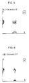
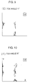
- Figs. 5 to 10 show the center-of-gravity when the toe angle is changed in the range from 5 to 20 degrees, respectively.
- Figs. 5 to 10 it can be seen that the center-of-gravity is most stable when the toe angle is at 10 and 15 degrees.
- the heel portion 3 does not contact the plane of walking (see Fig. 1), and therefore the person stands slightly tiptoe, which stimulates metatarsophalangeal joint. Therefore, antigravity muscles such as represented by the triceps surae (calves) related to the straight standing posture can be reinforced. Further, since the person stands tiptoe, toes of his or her feet are stimulated, function of grasping the ground is improved and thus the strength for supporting the body can be improved.
- Figs. 11 and 12 are schematic diagrams for explaining extension of the hip joint. Referring to Figs. 11 and 12, when forward rotation of the pelves is limited, the range of movement of extension of the hip joint is 15 degrees. Assuming that the ankle joint is perpendicular, the angle formed by the limb and the sole of the foot is 15 degrees. This corresponds to the kicking foot during walking in the state of kicking.
- the sports shoes has the toe angle in the range from 10 to 15 degrees in the state of kicking and 65% of the entire heel portion is in contact with the ground. Therefore, the kicking foot has sufficient area in contact with the ground, which makes stable the support of the standing legs. Therefore, the knee of the forward limb can be extended at ease, and at the same time, the time of flexion of the knee of the rearward limb can be retarded which increases the strength of the kicking foot, enabling smooth movement of the center-of-gravity.
- Fig. 13 is a diagram for comparing walking with the conventional casual shoes and with the sports shoes of the present invention. Referring to Fig.
- the third effect is that by setting the toe angle in the range from 10 to 15 degrees, strength of muscles can be efficiently exhibited.
- Fig. 14 shows the force which can be exhibited by the triceps surae (calf) corresponding to the change in the angle of the ankle joint. The force is strongest when the knee joint is extended and the ankle joint is at 10 degrees of planter flexion. It can be also seen from Fig. 14 that the force exhibited by muscles is decreased when one's knee is flexed. Accordingly, the rear leg can exhibit strongest kicking force during walking when his knee is extended and the ankle is at 10 degrees of planter flexion. As already described with reference to Figs. 11 and 12, extension of the hip joint is 15 degrees which corresponds to the kicking foot being about to kick during walking.
- FIGS. 15 and 16 are schematic diagrams for explaining the force to flex the knee exerted at the time of kicking by the rear limb.
- the force to flex the knee is more easily exerted as the area of toe in contact with the ground is smaller.
- the sports shoes of the present embodiment shown in Figs. 1 to 3 can provide sufficient area at the toe portion 4 in contact with the ground (65%), and therefore the force to flex the knee can be reduced and the force of muscles can be efficiently exhibit at the time of kicking.
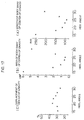
- Fig. 17 is a graph showing length of body sway of the center-of-gravity (A), the area of body sway of the center-of-gravity (B) and the displacement of the gravity (C) with the heel angle changed.
- A the length and area of body sway of the center-of-gravity
- B the area of body sway of the center-of-gravity
- C the displacement of the gravity
- Figs. 18 to 23 show the center-of-gravity with the heel angle changed in the range from 15 to 30 degrees. Referring to Figs. 18 to 23, it can be well understood that the center-of-gravity is stable when the heel angle is in the range of 20 to 25 degrees. In this manner, by setting the heel angle in the range from 20 to 25 degrees, stability of the standing posture can be obtained.
- the effect of stretching the triceps surae can be obtained. It is determined that the movable range of dorsiflexion of the ankle joint is measured with the subject setting with his knees flexed to release tension of the two-joint muscle (gastrocnemius) and the ankle moved by another person (manually operated by the measurer). Under this condition of measurement, the movable range of the joint of dorsiflexion shows the range from 0 to 20 degrees. However, when the knee is extended, the tension of the gastrocnemius is increased, and therefore the range is decreased to 14 degrees.
- the movable range is decreased to 10 degrees because of resistance of gastrocnemius and soleus, even when the knee is flexed. Further, when the knee is extended and dorsiflexion is done by the subject himself, the measured movable range is about 6 degrees. Therefore, when one stands with the heel 3 of the sports shoes in accordance with the present invention in contact with the plane of walking as shown in Fig. 3, the angle of dorsiflexion of the ankle is in the range from about 7 to about 9 degrees, and as this state, the triceps surae (calves) and hamstrings (muscle on the backside of thigh) are sufficiently stretched.
- Fig. 24 is a schematic diagram for explaining lordosis of lumber vertebra.
- a person keeps standing posture for a long period of time, the center-of-gravity moves toward the heels because of fatigue of antigravity muscles such as electro spinae and lumber vertebra is bent forward (lordosis) to change the posture to lessen burden on the antigravity muscles.
- this posture with lumber vertebra bent forward is a main factor causing low-back pain.
- Fig. 25 is a schematic diagram for explaining correction of lordosis when one wears the sports shoes of this embodiment.
- Fig. 25 when one keeps standing posture wearing the sport shoes of the present embodiment such as in the state shown in Fig. 3, tension of tibialis anterior, quadriceps femoris and abdominal muscle are induced in the front side of the body, so that lordosis of lumber vertebra can be corrected. Consequently, important factor of the low-back pain can be removed.
- the heel angle in the range from 20 to 25 degrees, stability of the forward limb during walking can be obtained. More specifically, it is generally known that largest shock is exerted when the forward limb reaches the ground and thereafter the sole as a whole is brought into contact with the ground during walking, as described above. Further, since the position of the heel portion 103 is higher than the position of the toe portion or toe 104 in the conventional casual shoes shown in Fig. 43, a force is exerted on the foot in the shoes to slip forward when at the moment when the sole 102 reaches the floor, the knee of the forward limb is relaxed and flexed, which applies a large force to the knee. By contrast, the sports shoes of the present embodiment shown in Fig.
- Figs. 26 and 27 are schematic diagrams for explaining the force to flex the knee exerted when the forward limb reaches the ground. Referring to Figs. 26 and 27, the knee tends to flex because of the rotational movement with the point in contact with the ground of the heel being the fulcrum in case of the conventional shoes.
- the sports shoes of the present embodiment the area for support across the heel portion 3 to the central portion of the sole can be ensured when the arch shaped heel 3 reaches the ground as shown in steps 3 and 4 of movement in Fig.
- the angle of dorsiflexion of the ankle joint can be made within the range of 7 to 10 degrees by the heel angle of 20 to 25 degrees so that slip of the foot forward in the shoes can be prevented, and rotational movement to the knee can be suppressed so that the knee is not flexed. Therefore, as shown in step 5 of the movement of Fig. 13, the leg extends straight and the weight can be supported by the entire sole.
- This way of walking is a highly skilled way of walking popular in competitive walking and it is the basic way of walking fast and smart. The force exerted to the knee can be reduced, and prevention of knee pain and of deformity of joint can be expected.
- the sports shoes of this embodiment has the toe angle in the range from 10 to 15 degrees, and within this range, the center-of-gravity of the wearer keeping standing posture is at a position approximately 52% from the tip end of the toe. Therefore, the support surface is effective when the supporting point 5 is behind this position.
- the support point 5 should not preferably be positioned at the region metatarsal bones, since the region metatarsal bones is not very strong.
- the support point 5 since the support point 5 also serves to support the arch, it should preferably be positioned at the region tarsal bones constituted by three cuneiform bone, navicular bone and cuboid bone (see Fig. 45) which approximately correspond to the center of the longitudinal arch. Therefore, the support point 5 should preferably be positioned in the range from 30 to 40% from the heel. In this embodiment, correspondingly, the support point is at the position 35% from the heel.
- Fig. 28 is a schematic diagram showing the concept of rocker sole deviced for those who having weak or enfeebled walking capability.
- the rocker sole absorbs shock to knees and hip joints and therefore it is suitable for use in shoes for aged persons, shoes for patients suffering from rheumatoid arthritis or shoes for persons with their legs became rigid.
- the rocker sole is rather inferior in stability at the standing posture.
- the rocker sole is adapted such that the center thereof is positioned at the central portion of the hip joint.
- FIG. 29 is a front view for explaining the rocker sole configuration of the sports shoes in accordance with the present invention.
- the sports shoes of the present embodiment each has a shape near an arch, which is similar to the rocker sole shown in Fig. 28. Accordingly, the center-of-gravity can be moved smooth. In addition, the stability, which could not be obtained by the rocker sole, is ensured by the heel portion 3 cut to have arch shaped in the sports shoes of this embodiment.
- Fig. 30 is a schematic diagram showing balance training using kinesthetic board.
- the same effect as the balance (proprioceptor kinesthetic sensation) training utilizing the kinesthetic board shown in Fig. 30 can be obtained by standing with the support point 5 of the sports shoes of the present embodiment shown in Figs. 1 to 3 being the center. This contributes to facilitation of muscles and nerves and improves balancing capability of one's body.
- Such training is called joint training. More specifically, by reinforcing muscles surrounding joints at the intermediate position which is most natural position of the joint, sprain of ankle joint, which is most popular among sport injury, can be prevented.
- FIGs. 31 and 32 are front views showing state of bending when the toe and the heel are depressed by both hands with the shoes supported only by the support point 5. Referring to Figs. 31 and 32, after loading, the toe and the heel are bent by about 5mm as compared with the state before loading, with the support point 5 being the center. It can be understood that such bending provides the function of supporting the arch of the sole in the sport shoes of the present embodiment.
- Fig. 33 is an illustration showing the mechanism of the arch configuration for dispersing shock. Referring to Fig. 33, when there is a load applied at the upper central portion of the arch configuration, the load is dispersed toward the lateral directions from both ends of the arch configuration.
- Figs. 34 and 35 are front views showing states before and after loading when the load of stand is applied on one foot wearing the sports shoe of the first embodiment. Referring to Figs. 34 and 35, by the load of stand on one foot, the arch of the heel portion 3 becomes lower by about 3mm, which can relieve the shock when the heel reaches the ground.
- the line B stimulates the arch of the foot, stretches the muscles on the sole, promotes blood flow and the effect of so called stamping on green bamboo section can be obtained.
- the B line When the wearer walks by using the line B and the AB surface of the sole, the B line simultaneously carries out the function of arch support and of stamping on green bamboo section and in addition, since the center-of-gravity of the shoes is in front, weight of one's body can be moved smooth.
- the BC arch absorbs shock during walking, and the wearer naturally walks in the correct manner because of the arch support, the effect of bamboo stamping, and of smooth movement of his or her weight.
- Ten women students are divided into group A (five students) and group B (five students) and the students wore the sports shoes of the first embodiment in campus and on the way to and from the campus.
- the students were suggested to bring into contact the arched heel of the sports shoes of the embodiment to stand, and to walk with the arched heel of the shoes reaching the ground first while walking, when they wore the sports shoes of the first embodiment.
- the items measured for determining the effects of the shoes were range of movement of ankle dorsiflexion and long sitting trunk flexion.
- the range of movement of ankle dorsiflexion was measured with the subjects' knees extended with the ankle moved by others (moved by hands of measurers).
- the measurement was carried out at the start of experiment, one week after the start of experiment and at the end of the experiment for the group A, while the measurement was carried out at the start of the experiment, at the end of the experiment and one week after the end of the experiment for the group B.
- the time of use of the sports shoes in accordance with the first embodiment was about 3.7 hours in average per day for the former one week, and about 3 hours in average per day for the latter one week in group A.
- the number of steps of the group A was about 2800 in average in the former half, while it was about 2300 in average per day for the latter week in group A.
- the time of use of the sports shoes in accordance with the present invention by the first group was about 4 hours in average per day in group B, and the average number of steps was about 1600 per a day.
- the change in the range of movement of ankle dorsiflexion under such condition was as shown in Tables 1 and 2 below.
- Fig. 36 is a graph showing the change in the long sitting trunk flexion when the group A used the sports shoes in accordance with the first embodiment for two weeks
- Fig. 37 is a graph showing the change in the long sitting trunk flexion when the group B used the sport shoes of the first embodiment for one week.
- the movable range of ankle dorsiflexion is improved by about one week, and as for the long sitting trunk flexion, flexibility is improved by about 2 weeks. It means that the effect of stretching of the triceps surae (calves) appears by about one week while the effect of stretching of hamstrings muscle appears by about two weeks.
- Use of the sports shoes in accordance with the first embodiment prevent decrease of flexibility caused by advance in age, and keeps and promotes function of controlling force exerted on joints.
- the physical capability is improved in every item: long sitting trunk flexion, 6cm; standing long jump, 16cm; vertical jump, 5cm; side step, 3 times; and 50m run, 0.3sec.
- these improvements have statistically significant meaning.
- the group not used the sports shoes of the embodiment exhibited improvements in items except 50m run, such improvements are not significant statistically.
- the sports shoes of the first embodiment allow zigzag or meandering as well as linear running, and allows free jumps and side steps in which the wearer moves rapidly in left and right directions. Therefore, training can be done in movements very close to the actual movement during sports. Therefore, not only the muscles but the muscular power can be trained.
- Fig. 38 is a front view showing a sport shoe in accordance with a second embodiment of the present invention.
- the support point portion 15 at the interface between the heel portion 13 and the toe portion 14 is formed by an area coupling a support point 15a and a support point 15b. Consequently, the rolling effect can be improved as compared with the first embodiment shown in Figs. 1 to 3.
- stability at foot flat state (the sole is flat) can be improved, and therefore shock absorbing capability can be improved.
- Fig. 39 is a front view showing a sport shoe in accordance with a third embodiment of the present invention.
- the sport shoe of the third embodiment has a heel portion 23 provided with two arches 23a and 23b.
- Fig. 40 is a bottom view showing the shape of the sole of the sport shoe in accordance with a fourth embodiment of the present invention.
- the shape of cutting 35 of the support point B is adapted such that it has inclination of 10 to 15 degrees from a position 35% from the rear end of the heel.
- the shape of cutting 33a of the surface 33c in contact with the ground at the heel is adapted to have an inclination in the range from 10 to 15 degrees.
- Fig. 41 is a schematic diagram showing this state.
- the angle of toe turned outward by about 10 to 15 degrees in the direction of walking is referred to as the angle of step.
- Such angle of step is caused as the tibia of the leg and the axis of the tibiotarsal joint of the foot are positioned at the lateral rotation angle of 10 to 15 degrees, which enables inversion and eversion movements (movement of center-of-gravity from the outer side to the inner side with respect to the ground), and shock absorption and stability are improved.
- FIG. 42 is a schematic diagram for explaining the movements of inversion and eversion during walking and during running.
- the movements of inversion and eversion during walking is plotted by the solid line while the movement of inversion and eversion during running is plotted by the dotted line. It is understood that the movement of inversion and eversion becomes larger during running than during walking. Since the shape of cutting 35 at the support point B and the shape of cutting 33a at the surface of the heel in contact with the ground 33c are formed to have inclinations in the range from 10 to 15 degrees in the sport shoes of the fourth embodiment shown in Fig. 40, this movement of inversion and eversion can be done smooth. As a result, movement of the ankle joint can be made more smooth.
- the present invention is not limited thereto and sports shoes having the configurations disclosed in these embodiments combined may be provided. In that case, sports shoes having the effects of the embodiments combined can be obtained.
- shock absorption and stability during strong movement on a hard ground such as asphalt can be improved, and shock absorption and movement of almost all sports can be enabled.
- the inner sole portion and the front sole portion are formed such that a line connecting the lower surface of the toe support point of one's foot and the lower surface of the heel portion forms an angle in the range from 10 to 15 degrees with respect to the plane of walking when a first bottom surface supporting the toe of one's foot which can be in contact with the plane of walking is brought into contact with the plane of walking, whereby when the wearer stands in tip toe state with the first bottom surface being in contact with the ground, muscles of calves can be trained, and the posture can be corrected.
- the front sole portion having the first surface and the rear sole portion having the second surface such that the first surface forms an angle in the range from 20 to 25 degrees with respect to the plane of walking when at least a portion of the second surface, which has a prescribed angle with the first surface supports the heel portion of one's foot and is capable of being in contact with the plane of walking, is brought into contact with the plane of walking, when the wearer stands with the second surface being in contact with the plane of walking, the calves can be stretched.
- the support portion at which the first and second surfaces interface with each other balancing sensation can be trained and the effect of the so called bamboo stamping can be obtained.
- a so called milking action of bringing back the blood at one's feet to the heart can be obtained.
Landscapes
- Footwear And Its Accessory, Manufacturing Method And Apparatuses (AREA)
Claims (5)
- Sportschuh mit:einem inneren Sohlenabschnitt, so daß ein Fuß einer Person in engem Kontakt damit ist; undeinem äußeren Sohlenabschnitt, der geformt ist, um fähig zu sein, mit einer Laufebene in Kontakt zu sein;wobei der äußere Sohlenabschnitt einen vorderen Sohlenabschnitt (4), der den Zehenabschnitt des Fußes einer Person hält, und eine erste Oberfläche besitzt, die in Kontakt mit der Laufebene sein kann, undeinen hinteren Sohlenabschnitt (3), der den Fersenabschnitt des Fußes einer Person abstützt, und eine zweite Oberfläche besitzt, die einen Winkel mit der ersten Oberfläche bildet, und die in Kontakt mit der Laufebene sein kann, umfaßt, dadurch gekennzeichnet, daß
der innere Sohlenabschnitt und der vordere Sohlenabschnitt (4) so geformt sind, daß eine Linie, die eine untere Oberfläche eines Zehenabstützpunkts des Fußes einer Person und eine untere Oberfläche der Ferse verbindet, einen Winkel im Abschnitt von 10 bis 15 Grad hinsichtlich der Laufebene bildet, wenn die erste Oberfläche in Kontakt mit der Laufebene ist,
wobei der vordere Sohlenabschnitt und der hintere Sohlenabschnitt so geformt sind, daß die erste Oberfläche einen Winkel im Bereich von 20 bis 25 Grad mit Bezug zu der Laufebene bildet, wenn zumindest ein Bereich der zweiten Oberfläche in Kontakt mit der Laufebene ist, wobei ein Stützpunkt (5, 15, 25, 35) zwischen dem vorderen Sohlenabschnitt (4, 14) und dem hinteren Sohlenabschnitt (3, 13, 23, 33) gebildet ist, und
der Stützpunkt (5, 15, 25, 35) an einer Position 30 bis 40 % von der gesamten Länge des Sportschuhs von dem hinteren Ende des Sohlenabschnitts (3, 13, 23, 33) gebildet ist,
und der vordere Sohlenabschnitt (4) ausgebildet ist, um einen Bereich zu umfassen, durch den eine vertikale Linie verläuft, die den Schwerpunkt des Körpers der Person enthält. - Sportschuh nach Anspruch 1, dadurch gekennzeichnet, daß die erste Oberfläche (3) eine gekrümmte Form hat.
- Sportschuh nach Anspruch 2, dadurch gekennzeichnet, daß die zweite Oberfläche (23) eine Vielzahl an gekrümmten Abschnitten (23a, 23b) umfaßt.
- Sportschuh nach Anspruch 1, dadurch gekennzeichnet, daß ein Stützbereich (15a, 15b, 15) mit einer dritten Oberfläche (15) zwischen dem vorderen Sohlenabschnitt (14) und dem hinteren Sohlenabschnitt (13) geformt ist.
- Sportschuh nach Anspruch 1, dadurch gekennzeichnet, daß ein Stützpunkt (35), der durch einen mit Bezug auf eine Richtung quer zu der Laufrichtung geneigten Winkel im Bereich von 10 bis 15 Grad geschnitten wird, an einer Grenzfläche zwischen dem vorderen Sohlenabschnitt und dem hinteren Sohlenabschnitt (33a, 33b, 33c) gebildet ist.
Applications Claiming Priority (2)
| Application Number | Priority Date | Filing Date | Title |
|---|---|---|---|
| JP82885/92U | 1992-12-01 | ||
| JP082885U JPH0645503U (ja) | 1992-12-01 | 1992-12-01 | 運動靴 |
Publications (2)
| Publication Number | Publication Date |
|---|---|
| EP0600145A1 EP0600145A1 (de) | 1994-06-08 |
| EP0600145B1 true EP0600145B1 (de) | 1997-09-03 |
Family
ID=13786731
Family Applications (1)
| Application Number | Title | Priority Date | Filing Date |
|---|---|---|---|
| EP93101367A Revoked EP0600145B1 (de) | 1992-12-01 | 1993-01-29 | Sportschuhe |
Country Status (4)
| Country | Link |
|---|---|
| EP (1) | EP0600145B1 (de) |
| JP (1) | JPH0645503U (de) |
| DE (1) | DE69313589T2 (de) |
| ES (1) | ES2106899T3 (de) |
Families Citing this family (8)
| Publication number | Priority date | Publication date | Assignee | Title |
|---|---|---|---|---|
| JPH07136001A (ja) * | 1993-11-11 | 1995-05-30 | Asuteiko:Kk | トレーニングシューズ |
| EP0838169A3 (de) * | 1996-09-07 | 1998-12-02 | Youngsoul Park | Fersenlose Schuhsohle mit Polsterung |
| ATE281086T1 (de) * | 1996-12-23 | 2004-11-15 | Svante Berggren | Sohlenaufbau |
| JP2791658B1 (ja) * | 1997-02-25 | 1998-08-27 | 京阪通商株式会社 | 靴の底およびそれを含む靴ならびにサンダル |
| EP0890322A1 (de) * | 1997-07-08 | 1999-01-13 | Dong-Hong Park | Schuhsohle |
| KR100652012B1 (ko) * | 2004-12-20 | 2006-11-30 | 코전트모션 주식회사 | 후방밸란스 워킹화 |
| US9629413B2 (en) | 2015-03-23 | 2017-04-25 | Karl Stien | Footwear with tapered heel, support plate, and impact point measurement methods therefore |
| CN105029828B (zh) * | 2015-07-24 | 2016-11-23 | 泉州市金运来工贸有限公司 | 一种高效健身跑步鞋 |
Citations (1)
| Publication number | Priority date | Publication date | Assignee | Title |
|---|---|---|---|---|
| US4722144A (en) * | 1985-07-12 | 1988-02-02 | Louis Beerli | Ski boot |
-
1992
- 1992-12-01 JP JP082885U patent/JPH0645503U/ja active Pending
-
1993
- 1993-01-29 DE DE69313589T patent/DE69313589T2/de not_active Revoked
- 1993-01-29 ES ES93101367T patent/ES2106899T3/es not_active Expired - Lifetime
- 1993-01-29 EP EP93101367A patent/EP0600145B1/de not_active Revoked
Patent Citations (1)
| Publication number | Priority date | Publication date | Assignee | Title |
|---|---|---|---|---|
| US4722144A (en) * | 1985-07-12 | 1988-02-02 | Louis Beerli | Ski boot |
Non-Patent Citations (5)
| Title |
|---|
| EP-A- 0 049 019 * |
| EP-A- 0 083 449 * |
| EP-A- 0 291 874 * |
| EP-A- 0 458 174 * |
| US-A- 4 722 144 * |
Also Published As
| Publication number | Publication date |
|---|---|
| JPH0645503U (ja) | 1994-06-21 |
| DE69313589T2 (de) | 1998-04-16 |
| EP0600145A1 (de) | 1994-06-08 |
| DE69313589D1 (de) | 1997-10-09 |
| ES2106899T3 (es) | 1997-11-16 |
Similar Documents
| Publication | Publication Date | Title |
|---|---|---|
| US9788597B2 (en) | Proprioceptive/kinesthetic apparatus and method | |
| US5507106A (en) | Exercise shoe with forward and rearward angled sections | |
| US6782639B1 (en) | Footwear for a dynamic, rolling walking-action | |
| US7603794B2 (en) | Rear balance walking shoes | |
| US9730489B2 (en) | High heel for exercising achilles tendons while walking | |
| US20190374813A1 (en) | Physical Training and Rehabilitation Device and Methods for Using Same | |
| KR102338412B1 (ko) | 발바닥 근육 강화용 패드, 이를 포함하는 인솔 | |
| KR100960562B1 (ko) | 중족부에 운동성을 부여할 수 있는 기능성 신발 깔창 | |
| EP0600145A1 (de) | Sportschuhe | |
| JP2001511375A (ja) | スポーツシューズ内で足を支持するための装置 | |
| Subotnick | Foot orthoses: an update | |
| EP2949234B1 (de) | Propriozeptive/kinästhetische vorrichtung und verfahren | |
| US20120000093A1 (en) | Perfect Gait Shoe | |
| JP3019544U (ja) | 運動靴 | |
| RU2759112C1 (ru) | Обувь для укрепления и расслабления мышц ступни и голени (варианты) и комплект для повышения общей физической подготовленности организма | |
| US11511153B2 (en) | Apparatus reducing compensatory leg, ankle and foot movements during heel raise exercises in rehabilitation and fitness | |
| KR200301689Y1 (ko) | 기능성 건강신발 | |
| JP2024175628A (ja) | インソールおよび履物 | |
| KR200172186Y1 (ko) | 역방향 기능성 워킹화 | |
| JPH07136001A (ja) | トレーニングシューズ | |
| Humble et al. | Hockey Skate Boots | |
| KR20060048563A (ko) | 자세교정 및 다이어트용 신발 | |
| KR19990084044A (ko) | 역방향 기능성 워킹화 | |
| JPH10286104A (ja) | 先端部分を後部より高くした履物 | |
| JPH11285401A (ja) | 靴の底 |
Legal Events
| Date | Code | Title | Description |
|---|---|---|---|
| PUAI | Public reference made under article 153(3) epc to a published international application that has entered the european phase |
Free format text: ORIGINAL CODE: 0009012 |
|
| 17P | Request for examination filed |
Effective date: 19930901 |
|
| AK | Designated contracting states |
Kind code of ref document: A1 Designated state(s): DE ES FR GB IT |
|
| 17Q | First examination report despatched |
Effective date: 19960701 |
|
| GRAG | Despatch of communication of intention to grant |
Free format text: ORIGINAL CODE: EPIDOS AGRA |
|
| GRAH | Despatch of communication of intention to grant a patent |
Free format text: ORIGINAL CODE: EPIDOS IGRA |
|
| GRAH | Despatch of communication of intention to grant a patent |
Free format text: ORIGINAL CODE: EPIDOS IGRA |
|
| GRAA | (expected) grant |
Free format text: ORIGINAL CODE: 0009210 |
|
| AK | Designated contracting states |
Kind code of ref document: B1 Designated state(s): DE ES FR GB IT |
|
| ITF | It: translation for a ep patent filed | ||
| REF | Corresponds to: |
Ref document number: 69313589 Country of ref document: DE Date of ref document: 19971009 |
|
| ET | Fr: translation filed | ||
| REG | Reference to a national code |
Ref country code: ES Ref legal event code: FG2A Ref document number: 2106899 Country of ref document: ES Kind code of ref document: T3 |
|
| PGFP | Annual fee paid to national office [announced via postgrant information from national office to epo] |
Ref country code: GB Payment date: 19980109 Year of fee payment: 6 |
|
| PGFP | Annual fee paid to national office [announced via postgrant information from national office to epo] |
Ref country code: FR Payment date: 19980119 Year of fee payment: 6 |
|
| PGFP | Annual fee paid to national office [announced via postgrant information from national office to epo] |
Ref country code: ES Payment date: 19980126 Year of fee payment: 6 |
|
| PGFP | Annual fee paid to national office [announced via postgrant information from national office to epo] |
Ref country code: DE Payment date: 19980323 Year of fee payment: 6 |
|
| PLBQ | Unpublished change to opponent data |
Free format text: ORIGINAL CODE: EPIDOS OPPO |
|
| PLBI | Opposition filed |
Free format text: ORIGINAL CODE: 0009260 |
|
| PLBF | Reply of patent proprietor to notice(s) of opposition |
Free format text: ORIGINAL CODE: EPIDOS OBSO |
|
| 26 | Opposition filed |
Opponent name: YOUNGSOUL PARK Effective date: 19980602 |
|
| PLBF | Reply of patent proprietor to notice(s) of opposition |
Free format text: ORIGINAL CODE: EPIDOS OBSO |
|
| PG25 | Lapsed in a contracting state [announced via postgrant information from national office to epo] |
Ref country code: GB Free format text: LAPSE BECAUSE OF NON-PAYMENT OF DUE FEES Effective date: 19990129 |
|
| PG25 | Lapsed in a contracting state [announced via postgrant information from national office to epo] |
Ref country code: ES Free format text: LAPSE BECAUSE OF NON-PAYMENT OF DUE FEES Effective date: 19990130 |
|
| PLBF | Reply of patent proprietor to notice(s) of opposition |
Free format text: ORIGINAL CODE: EPIDOS OBSO |
|
| PLBF | Reply of patent proprietor to notice(s) of opposition |
Free format text: ORIGINAL CODE: EPIDOS OBSO |
|
| GBPC | Gb: european patent ceased through non-payment of renewal fee |
Effective date: 19990129 |
|
| PG25 | Lapsed in a contracting state [announced via postgrant information from national office to epo] |
Ref country code: FR Free format text: LAPSE BECAUSE OF NON-PAYMENT OF DUE FEES Effective date: 19990930 |
|
| PG25 | Lapsed in a contracting state [announced via postgrant information from national office to epo] |
Ref country code: DE Free format text: LAPSE BECAUSE OF NON-PAYMENT OF DUE FEES Effective date: 19991103 |
|
| REG | Reference to a national code |
Ref country code: FR Ref legal event code: ST |
|
| RDAH | Patent revoked |
Free format text: ORIGINAL CODE: EPIDOS REVO |
|
| RDAG | Patent revoked |
Free format text: ORIGINAL CODE: 0009271 |
|
| STAA | Information on the status of an ep patent application or granted ep patent |
Free format text: STATUS: PATENT REVOKED |
|
| 27W | Patent revoked |
Effective date: 19991224 |