EP0600158B1 - Dispositif de conduction de la lumière pour le couplage électro-optique vers le panneau d'affichage d'un instrument électronique - Google Patents
Dispositif de conduction de la lumière pour le couplage électro-optique vers le panneau d'affichage d'un instrument électronique Download PDFInfo
- Publication number
- EP0600158B1 EP0600158B1 EP93112826A EP93112826A EP0600158B1 EP 0600158 B1 EP0600158 B1 EP 0600158B1 EP 93112826 A EP93112826 A EP 93112826A EP 93112826 A EP93112826 A EP 93112826A EP 0600158 B1 EP0600158 B1 EP 0600158B1
- Authority
- EP
- European Patent Office
- Prior art keywords
- light
- light pipes
- electronic instrument
- display panel
- printed circuit
- Prior art date
- Legal status (The legal status is an assumption and is not a legal conclusion. Google has not performed a legal analysis and makes no representation as to the accuracy of the status listed.)
- Expired - Lifetime
Links
Images


Classifications
-
- G—PHYSICS
- G09—EDUCATION; CRYPTOGRAPHY; DISPLAY; ADVERTISING; SEALS
- G09F—DISPLAYING; ADVERTISING; SIGNS; LABELS OR NAME-PLATES; SEALS
- G09F9/00—Indicating arrangements for variable information in which the information is built-up on a support by selection or combination of individual elements
- G09F9/30—Indicating arrangements for variable information in which the information is built-up on a support by selection or combination of individual elements in which the desired character or characters are formed by combining individual elements
- G09F9/305—Indicating arrangements for variable information in which the information is built-up on a support by selection or combination of individual elements in which the desired character or characters are formed by combining individual elements being the ends of optical fibres
-
- G—PHYSICS
- G01—MEASURING; TESTING
- G01D—MEASURING NOT SPECIALLY ADAPTED FOR A SPECIFIC VARIABLE; ARRANGEMENTS FOR MEASURING TWO OR MORE VARIABLES NOT COVERED IN A SINGLE OTHER SUBCLASS; TARIFF METERING APPARATUS; MEASURING OR TESTING NOT OTHERWISE PROVIDED FOR
- G01D11/00—Component parts of measuring arrangements not specially adapted for a specific variable
- G01D11/28—Structurally-combined illuminating devices
-
- G—PHYSICS
- G02—OPTICS
- G02B—OPTICAL ELEMENTS, SYSTEMS OR APPARATUS
- G02B6/00—Light guides; Structural details of arrangements comprising light guides and other optical elements, e.g. couplings
- G02B6/0001—Light guides; Structural details of arrangements comprising light guides and other optical elements, e.g. couplings specially adapted for lighting devices or systems
- G02B6/0005—Light guides; Structural details of arrangements comprising light guides and other optical elements, e.g. couplings specially adapted for lighting devices or systems the light guides being of the fibre type
- G02B6/0006—Coupling light into the fibre
-
- G—PHYSICS
- G02—OPTICS
- G02B—OPTICAL ELEMENTS, SYSTEMS OR APPARATUS
- G02B6/00—Light guides; Structural details of arrangements comprising light guides and other optical elements, e.g. couplings
- G02B6/0001—Light guides; Structural details of arrangements comprising light guides and other optical elements, e.g. couplings specially adapted for lighting devices or systems
- G02B6/0005—Light guides; Structural details of arrangements comprising light guides and other optical elements, e.g. couplings specially adapted for lighting devices or systems the light guides being of the fibre type
- G02B6/0008—Light guides; Structural details of arrangements comprising light guides and other optical elements, e.g. couplings specially adapted for lighting devices or systems the light guides being of the fibre type the light being emitted at the end of the fibre
-
- G—PHYSICS
- G02—OPTICS
- G02B—OPTICAL ELEMENTS, SYSTEMS OR APPARATUS
- G02B6/00—Light guides; Structural details of arrangements comprising light guides and other optical elements, e.g. couplings
- G02B6/24—Coupling light guides
- G02B6/42—Coupling light guides with opto-electronic elements
- G02B6/4298—Coupling light guides with opto-electronic elements coupling with non-coherent light sources and/or radiation detectors, e.g. lamps, incandescent bulbs, scintillation chambers
-
- Y—GENERAL TAGGING OF NEW TECHNOLOGICAL DEVELOPMENTS; GENERAL TAGGING OF CROSS-SECTIONAL TECHNOLOGIES SPANNING OVER SEVERAL SECTIONS OF THE IPC; TECHNICAL SUBJECTS COVERED BY FORMER USPC CROSS-REFERENCE ART COLLECTIONS [XRACs] AND DIGESTS
- Y10—TECHNICAL SUBJECTS COVERED BY FORMER USPC
- Y10S—TECHNICAL SUBJECTS COVERED BY FORMER USPC CROSS-REFERENCE ART COLLECTIONS [XRACs] AND DIGESTS
- Y10S362/00—Illumination
- Y10S362/80—Light emitting diode
Definitions
- This invention relates generally to the electro-optical coupling to display panels for certain electronic instruments from the internal electronics thereof. More particularly, this invention relates to the use of light pipes to create a novel and cost effective design and construction for the opto-electronics of computers, printers, copiers, or other similar electronic equipment.
- PCBs printed circuit boards
- LEDs light emitting diodes
- DE-A-3048288 discloses an arrangement comprising a plurality of LEDs supported on a support plate and further comprising a reflector body having a plurality of light exit openings for deflecting the light emitted by the LEDs through the openings in a direction which is essentially parallel to the major surface of the support plate.
- EP-A-0310889 and US-A-4,106,231 disclose curved light pipes.
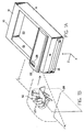
- Figure 1A is a perspective view of a printer or copier housing in which the present invention may be used.
- Figure 1B is an enlarged perspective view showing the one piece molded light pipe construction as it is oriented vertically within the electronic instrument housing of Figure 1A, and with the beveled edges of the vertical frame pieces abutting the far surface of the printed circuit board.
- Figure 2 is a plan view looking from left to right into the left hand side of the printer or copier shown in Figure 1A and toward the far facing surface of the PC board shown in Figure 1B.
- Figure 2 shows the LED mounting arrangement on the printed circuit board and the light pipe coupling from the LEDs and along an approximate 90° curved path to the top of the printer or copier housing.
- Figure 3A is an enlarged perspective view showing the one piece molded construction for the light pipes and supporting frame members therefor and removed from the printed circuit board of Figure 1B.
- Figure 3B is a reverse angle perspective view of the one piece molded construction for the light pipe arrangement shown in Figure 3A.
- Figure 4 is a perspective view of a single light pipe to better illustrate its precise external contours and to show a light emitting diode located adjacent to the lower end of the light pipe.
- Figure 5A is an enlarged cross-section view of a single light pipe which shows the radius of curvature, R, the maximum light pipe thickness, t, and the internal light transmission characteristics of the light pipe.
- Figure 5B shows an alternative LED mounting arrangement which may be used for the above light pipes.
- a printer or copier housing 10 which will typically include a top wall 12, side walls 14 and 15, and a front wall 16 of conventional construction.
- a printer and in the example herein as shown in Figure 1, an input paper cassette 18 is received in an opening in the front wall 16, and printed sheets of paper are collected in an output sheet receiving tray or bin 20.
- the section 22 of the printer 10 which is bounded by the far side wall 15 is configured to receive internal thereto the light pipe apparatus shown in the enlarged perspective view of Figure 1B and also in plan view in Figure 2 described below.
- This section 22 includes a display panel 24 therein, and this display panel may contain letters, numbers (e.g. 1, 2, 3, 4 code numbers), or symbols which are lighted by the selective energization of the LEDs on the PC board described below.
- the code numbers 1, 2, 3, 4 are merely representative of four (4) parameters of printer or copier operation which provide a visual indication to the user of the presence or absence of certain operating conditions of the printer or copier.
- FIG. 1B there is shown an enlarged perspective view of how the one piece molded light pipe assembly 25 is mounted on a top section of a printed circuit board 28, both of which are described in greater detail below.
- the upper ends of the four curved light pipes, e.g. light pipe 52, are optically coupled respectively into the four display lens, e.g. lens code number 1, in the display panel 24 in Figure 1A.
- These light emitting diodes (LEDs) 30, 32, 34, and 36 shown in the remaining figures are selectively energized by electrical signals received from the PC board 28 to in turn propagate light upwardly in each of these light pipes and into the lens (1, 2, 3, 4) within the display panel 24.
- LEDs light emitting diodes
- the printed circuit board 28 is multi-functional in purpose and operation in that it has been previously set and connected in place using only one set of electrical cabling within the instrument housing 10.
- the PC board 28 is used for also performing other electronic signal processing functions in addition to the electro-optical ones described herein.
- the printed circuit board 28 will now include, in addition to its previously existing components and functions, a plurality of light emitting diodes 30, 32, 34, and 36 mounted as shown in the upper right hand corner of the PC board 28.
- Each LED is electro-optically coupled to a corresponding one of a plurality of curved light pipes 38, 40, 42, and 44, respectively.
- These light pipes 38, 40, 42, and 44 are of a tapered configuration as shown, with the light output ends 46, 48, 50, and 52 thereof extending into individual output display lens areas of the top region 22 of the electronic instrument housing 10.
- the light pipes 46, 48, 50, and 52 are preferably constructed of a polycarbonate material and are joined together in a one-piece molded construction which includes a single horizontal cross piece or frame member 54 and two alignment pieces or frame members 56 and 58.
- the vertical frame members 56 and 58 are formed in the configuration shown and are used to align the light pipes in the Z axis, or perpendicular to the plane of the printed circuit board 28.
- the horizontal cross piece 54 has a downwardly contoured and angled end portion 59 which is received in a mating U-shaped slot 60 in the PC board 28 for aligning the light pipes 38, 40, 42, and 44 perpendicular to both the X and Y components of the light pipes within the instrument housing 10.
- the alignment frame members 56 and 58 extend vertically as shown adjacent to the abutting major surface of the PC board 28 and have beveled edges described below which operate to provide a slight physical separation between the lower ends of the light pipes 38, 40, 42, and 44 and the LEDs 30, 32, 34, and 36.
- these LEDs serve to propagate light upwardly through the light pipes 38, 40, 42, and 44 and along an approximate 90° radius of curvature and into the code 1-4 lens areas on the upper surface 26 of the printer or copier housing 10 which cover the smaller upper light projecting ends 46, 48, 50, and 52 of these light pipes.
- FIG. 3A and 3B there is shown in two oppositely oriented perspective views the one piece molded part in which the plurality of upwardly curved light pipes 38, 40, 42, and 44 are integrally attached to the horizontal support member or platform 54 having the downwardly extending flange 59 which is contoured to engage the mating angled slot 60 in the printed circuit board 28 shown in Figure 2.
- the pair of vertical upstanding rib members 56 and 58 are also integrated into the one piece molded construction 25 and include the downwardly extending beveled ends 62 and 64 which are operative to receive the upper edges of the printed circuit board 28 as the assembly 25 is positioned in place as shown in Figure 1B and Figure 2.
- This edge-to-PC board abutment serves to gradually separate the printed circuit board 28 from the lower ends of the light pipes 38, 40, 42, and 44 and thereby provide a small space of about 0.020 inches between these light pipe ends and the corresponding facing surfaces of the light emitting diodes 30, 32, 34, and 36. This feature thus provides the assembly tolerances which are necessary to prevent damage to the LEDs 30, 32, 34, and 36.
- the upper ends of the upstanding rib members 56 and 58 include the flat plate fixtures 66 and 68 having therein openings 70 and 72, respectively, for being bolted to the upper surface of an instrument housing 10.
- This bolting to the upper cover 22 of the instrument housing 10 is done prior to aligning the cover 22 to the printed circuit board 28.
- the instrument assembler can readily ease the angled extended flange 59 into the mating receiving slot 60 on the PC board 28 by self alignment without actually seeing this 59-60 fitting and with the cover 22 being oriented in the visually shielding position shown in Figure 1A.
- Each individual light pipe 38, 40, 42, and 44 is integrally joined to the horizontal support member or platform 54 by means of a plurality of horizontally extending rib members 74, 76, 78, and 80, each of which extend into direct and integral contact with the respective light pipes at approximately the center point 82 of the 90° radius of curvature for each these light pipes.
- the light receiving ends, e.g. 63 and 65, of the light pipes are preferably flat in order to minimize transmission losses due to misalignment with the centers of the respective LEDs 30, 32, 34, and 36.
- Figure 4 there is shown in an enlarged perspective view a single light pipe 44 in order to better illustrate the exact shape and contour of each pipe.
- Figure 4 shows the 90° radius of curvature from the light receiving face 81 to the light projecting face 83.
- Figure 4 also shows the taper of the light pipe from an area of 4 X 5 millimeters at the light receiving end 81 down to an area of 1.5 X 4 millimeters at the light projecting end 83 thereof.
- the light receiving face 81 is located very closely adjacent to the LED 85 as previously indicated, and the light pipe 44 will preferably be constructed of a polycarbonate material such as a material sold under the tradename LEXAN Color No. 111-N and available from the Plastics Division of the General Electric Company.
- the radius of curvature R shown therein is equal to, or greater than, three times the thickness dimension, t, at its point 82 of maximum thickness.
- the exact location of the light pipe surface region joining the rib support members 74 is not critical inasmuch as there will be very little light impinging on the inside surface of the light pipe wall adjacent to the light void region 84 as indicated in Figure 5A.
- This light void region 84 is defined by the direction of the propagated light waves shown in Figure 5A which emanate from the light emitting diode or LED 85 mounted closely adjacent to the lower flat surface 81 of the light pipe 44.
- the present invention may be also used in scanners and facsimile machines as well as printers or copiers, and it may be employed with a variety of LED configurations constructed on a major surface of a printed circuit board.
- the present invention is not limited to the particular configuration and curvature of the plurality of light pipes or to the specific design of the one-piece molded construction of which the light pipes are an integral part.
- the angled flange 59 may be made vertical if desired.
- the present invention is intended to cover the transmission of light from any type of PC board source to various types of display panels containing numbers, letters, symbols, or other types of display characters thereon.
- the PC board 28 may be mounted horizontally within the instrument housing 10 and used with the curved light pipes to project light onto a vertical front or side wall of the instrument housing on which a display panel is mounted.
Landscapes
- Physics & Mathematics (AREA)
- General Physics & Mathematics (AREA)
- Optics & Photonics (AREA)
- Engineering & Computer Science (AREA)
- Theoretical Computer Science (AREA)
- Devices For Indicating Variable Information By Combining Individual Elements (AREA)
- Illuminated Signs And Luminous Advertising (AREA)
- Accessory Devices And Overall Control Thereof (AREA)
Claims (10)
- Conduit de lumière courbé (38, 40, 42, 44) susceptible d'être utilisé dans un dispositif de conduction et d'alignement de la lumière pour le couplage electro-optique vers le panneau d'affichage d'un instrument électronique (10) du type comportant au moins une carte de circuit imprimé (28) montée dans celui-ci, pour modifier le chemin de parcours de la lumière, de 90° environ depuis une direction normale à une surface majeure de la carte de circuit imprimé (28), vers une direction normale au panneau d'affichage (24), caractérisé en ce que le rayon de courbure R (figure 5A) dudit conduit de lumière (38, 40, 42, 44) est égal ou supérieur à trois fois l'épaisseur maximale t dudit conduit de lumière.
- Conduit de lumière (39, 40, 42, 44) selon la revendication 1, dans lequel une extrémité (81) dudit conduit de lumière (44), dans laquelle doit s'engager un dispositif électroluminescent (85), est soit plate, soit parabolique, et l'autre extrémité plus petite (83) dudit conduit de lumière, destinée à propager la lumière vers ledit panneau d'affichage, est soit plate, soit ondulée soit concave, soit tissée.
- Structure unitaire comprenant:a. une pluralité de conduits de lumière (38, 40, 42, 44) selon la revendication 1 ou 2, et contigus à un organe formant support horizontal (54), qui aligne lesdits conduits sur des axes d'orientation X et Y, situés à l'intérieur du boîtier dudit instrument électronique (10), etb. une paire d'organes formant nervures droites (56, 58) qui traversent ou qui sont adjacents audit organe formant support horizontal (54), pour aligner lesdits conduits de lumière (38, 40, 42, 44) sur l'axe d'orientation Z, situé à l'intérieur du boîtier dudit instrument électronique (10).
- Dispositif de conduction et d'alignement de la lumière pour le couplage electro-optique vers le panneau d'affichage d'un instrument électronique (10) du type comportant au moins une carte de circuit imprimé (28) montée dans celui-ci, comprenant:a. une pluralité de diodes électroluminescentes (LED) (30, 32, 34, 36), situées sur une surface majeure de la carte de circuit imprimé (28), qui est positionnée de façon sensiblement normale par rapport à la surface du panneau d'affichage (24) du boîtier d'un instrument électronique (10), etb. une pluralité de conduits de lumière (38, 40, 42, 44) selon la revendication 1 ou 2.
- Dispositif selon la revendication 4, dans lequel ladite pluralité de conduits de lumière (38, 40, 42, 44) sont réunis en organes formant cadres verticaux (56, 58) et horizontaux (54) d'une construction en un élément moulé, et fonctionnent en alignant lesdits conduits sur l'ensemble des axes X, Y et Z, situés à l'intérieur du boîtier dudit instrument électronique.
- Dispositif selon les revendications 4 ou 5, dans lequel un organe formant cadre horizontal (54) aligne lesdits conduits (38, 40, 42, 44) sur les axes X et Y, et une paire d'organes formant cadres verticaux (56, 58) alignent lesdits conduits sur l'axe Z du boîtier dudit instrument électronique (10).
- Dispositif selon les revendications 4, 5 ou 6, dans lequel lesdits conduits (38, 40, 42, 44) sont effilés depuis une grande extrémité (81), où est située chaque LED, et vers une petite extrémité (83), qui est couplée optiquement audit panneau d'affichage (24) du boîtier dudit instrument électronique (10).
- Dispositif selon les revendications 5, 6 ou 7, dans lequel lesdits organes formant cadres verticaux (56, 58) comportent des fixations pour boulonnage (66, 68) à leurs extrémités supérieures, pour la fixation d'un organe formant couvercle (22) dudit instrument électronique (10), de façon qu'un monteur puisse aligner lesdits conduits de lumière avec lesdites LED, en plaçant ledit couvercle (22) au-dessus dudit boîtier (10).
- Dispositif selon la revendication 8, dans lequel ledit organe formant support horizontal (54) a une partie d'extrémité faisant saillie (59), pour s'engager dans une fente (60) située dans ladite carte de circuit imprimé (28), de façon à faciliter l'alignement automatique desdits conduits de lumière avec lesdites LED.
- Dispositif selon les revendications 8 ou 9, dans lequel lesdits organes formant nervures droites (56, 58) comportent un bord biseauté à une extrémité (62, 64) de ceux-ci, pour venir en contact avec un bord de ladite carte de circuit imprimé (28), et éloigner lesdites diodes électroluminescentes (30, 32, 34, 36) situées sur celle-ci, d'une faible longueur prédéterminée, des surfaces d'extrémité adjacentes desdits conduits de lumière (38, 40, 42, 44), comme requis par les tolérances de montage.
Applications Claiming Priority (2)
| Application Number | Priority Date | Filing Date | Title |
|---|---|---|---|
| US984035 | 1992-12-01 | ||
| US07/984,035 US5268823A (en) | 1992-12-01 | 1992-12-01 | Light transmission apparatus for electro-optically coupling to a display panel for an electronic instrument |
Publications (2)
| Publication Number | Publication Date |
|---|---|
| EP0600158A1 EP0600158A1 (fr) | 1994-06-08 |
| EP0600158B1 true EP0600158B1 (fr) | 1997-02-12 |
Family
ID=25530254
Family Applications (1)
| Application Number | Title | Priority Date | Filing Date |
|---|---|---|---|
| EP93112826A Expired - Lifetime EP0600158B1 (fr) | 1992-12-01 | 1993-08-10 | Dispositif de conduction de la lumière pour le couplage électro-optique vers le panneau d'affichage d'un instrument électronique |
Country Status (4)
| Country | Link |
|---|---|
| US (1) | US5268823A (fr) |
| EP (1) | EP0600158B1 (fr) |
| JP (1) | JP3604712B2 (fr) |
| DE (1) | DE69308108T2 (fr) |
Families Citing this family (44)
| Publication number | Priority date | Publication date | Assignee | Title |
|---|---|---|---|---|
| US5349504A (en) * | 1993-07-12 | 1994-09-20 | Dialight Corporation | Multi-level lightpipe design for SMD LEDs |
| US5504660A (en) * | 1994-01-03 | 1996-04-02 | Illinois Tool Works Inc. | Lens retention structure |
| US5613750A (en) * | 1994-11-07 | 1997-03-25 | Delco Electronics Corporation | Fluorescent backlighting device for an instrument panel |
| US5790041A (en) * | 1995-02-14 | 1998-08-04 | Advanced Micro Devices, Inc. | Apparatus and method to display network connection status on a jack panel |
| US5515244A (en) * | 1995-04-03 | 1996-05-07 | Apple Computer, Inc. | Light-transmitting pipe |
| AU695608B2 (en) * | 1995-06-07 | 1998-08-20 | Toyoda Gosei Co. Ltd. | Light-driven display device |
| US5785404A (en) * | 1995-06-29 | 1998-07-28 | Siemens Microelectronics, Inc. | Localized illumination device |
| WO1997001728A1 (fr) * | 1995-06-29 | 1997-01-16 | Siemens Components, Inc. | Eclairage localise realise selon la technique de la reflexion totale |
| JPH0997016A (ja) * | 1995-10-02 | 1997-04-08 | Oki Electric Ind Co Ltd | 電子機器の表示装置 |
| US5938324A (en) * | 1996-10-07 | 1999-08-17 | Cisco Technology, Inc. | Light pipe |
| US5861815A (en) * | 1997-01-24 | 1999-01-19 | Silicon Graphics, Inc. | Light bar and reflector assembly |
| US5877863A (en) * | 1997-03-20 | 1999-03-02 | Bayer Corporation | Readhead for a photometric diagnostic instrument |
| US6095851A (en) * | 1997-11-17 | 2000-08-01 | Xircom, Inc. | Status indicator for electronic device |
| DE19847789B4 (de) * | 1998-10-16 | 2017-02-23 | Sew-Eurodrive Gmbh & Co Kg | Umrichterbaureihe |
| FR2786573B1 (fr) * | 1998-12-01 | 2002-06-14 | Eastman Kodak Co | Systeme de signalisation pour locaux obscurs utilisant des conducteurs de lumiere et procede de couplage d'une diode et d'un conducteur de lumiere |
| DE19857862A1 (de) * | 1998-12-15 | 2000-06-29 | Mannesmann Vdo Ag | Anzeigeeinheit |
| US6457992B2 (en) | 1999-02-08 | 2002-10-01 | 3Com Corporation | Visual feedback system for electronic device |
| US6527411B1 (en) * | 2000-08-01 | 2003-03-04 | Visteon Corporation | Collimating lamp |
| WO2002027697A2 (fr) * | 2000-09-29 | 2002-04-04 | Ge Fanuc Automation North America, Inc. | Appareil a conduit de lumiere |
| DE10112640C1 (de) * | 2001-03-16 | 2002-12-19 | Diehl Ako Stiftung Gmbh & Co | Anzeigeeinrichtung |
| US6899273B2 (en) | 2001-05-02 | 2005-05-31 | Hand Held Products, Inc. | Optical reader comprising soft key including permanent graphic indicia |
| US6608750B2 (en) | 2001-06-27 | 2003-08-19 | Sun Microsystems, Inc. | Handle-mounted light conduit for a storage device carrier |
| US6473300B1 (en) | 2001-06-27 | 2002-10-29 | Sun Microsystems, Inc. | Light conduit for a storage device carrier assembly |
| US7592972B2 (en) * | 2001-11-15 | 2009-09-22 | Continental Automotive Systems Us, Inc. | Thin instrument cluster |
| JP3753117B2 (ja) * | 2002-09-17 | 2006-03-08 | ヤマハ株式会社 | 電子機器およびその表示器取付方法 |
| US20040097912A1 (en) * | 2002-11-18 | 2004-05-20 | Gonnering Wayne J. | Electrosurgical generator and method with removable front panel having replaceable electrical connection sockets and illuminated receptacles |
| US7193405B2 (en) * | 2004-06-07 | 2007-03-20 | The Stanley Works | Electronic multi-depth object locator with self-illuminating optical element warning and detection |
| US7209627B2 (en) * | 2004-08-31 | 2007-04-24 | Hewlett-Packard Development Company, L.P. | Lightpipe with multiple projections |
| DE102005013804A1 (de) * | 2005-03-24 | 2006-09-28 | BSH Bosch und Siemens Hausgeräte GmbH | Beleuchtetes Anzeigefenster für LED- und/oder LC-Anzeigen |
| US7673804B1 (en) | 2005-11-14 | 2010-03-09 | Hand Held Products, Inc. | Handle for portable data terminal |
| US7748632B2 (en) * | 2006-07-25 | 2010-07-06 | Hand Held Products, Inc. | Portable data terminal and battery therefor |
| DE102007016923A1 (de) * | 2007-04-05 | 2008-10-09 | Odelo Gmbh | Lichtleitkörper und Leuchteinheit mit Lichtleitkörper |
| US8178802B2 (en) | 2008-07-31 | 2012-05-15 | Electrolux Home Products, Inc. | Unitized appliance control panel assembly and components of the assembly |
| GB2464963A (en) * | 2008-10-31 | 2010-05-05 | Siemens Ag | A display comprising cranked light guides |
| CN101751824B (zh) * | 2008-12-19 | 2012-06-20 | 鸿富锦精密工业(深圳)有限公司 | 显示装置 |
| JP2011165608A (ja) * | 2010-02-15 | 2011-08-25 | Sanyo Electric Co Ltd | 表示装置および投写型表示装置 |
| US9189669B2 (en) | 2010-06-24 | 2015-11-17 | Metrologic Instruments, Inc. | Distinctive notice for different symbology information |
| US9589164B2 (en) | 2010-06-24 | 2017-03-07 | Metrologic Instruments, Inc. | Distinctive notice for different symbology information |
| JP5561153B2 (ja) * | 2010-12-27 | 2014-07-30 | ティアック株式会社 | 電子機器および導光レンズの取り付け方法 |
| ITTO20120707A1 (it) * | 2012-08-06 | 2014-02-07 | Magneti Marelli Spa | Procedimento di realizzazione per ottenere un dispositivo guida-luce atto ad illuminare una pluralita' di indicatori in un quadro di controllo, e dispositivo guida-luce realizzato secondo tale procedimento |
| CN104838204A (zh) * | 2012-09-20 | 2015-08-12 | 汤姆逊许可公司 | 面板照明系统 |
| JP2015173057A (ja) * | 2014-03-12 | 2015-10-01 | ヤマハ株式会社 | 音響機器及びその線状照明具用ブラケット |
| JP2017527967A (ja) | 2014-09-10 | 2017-09-21 | トムソン ライセンシングThomson Licensing | 電子機器のための多重ライトパイプ構造 |
| CA3015210A1 (fr) | 2016-02-26 | 2017-08-31 | Magic Leap, Inc. | Systeme d'affichage ayant une pluralite de conducteurs de lumiere pour une pluralite d'emetteurs de lumiere |
Family Cites Families (11)
| Publication number | Priority date | Publication date | Assignee | Title |
|---|---|---|---|---|
| US3142235A (en) * | 1960-11-21 | 1964-07-28 | American Optical Corp | Catadioptric optical systems for cameras and the like |
| US3439157A (en) * | 1966-02-11 | 1969-04-15 | Singer General Precision | Point light source |
| JPS52138947A (en) * | 1976-05-17 | 1977-11-19 | Copal Co Ltd | Light diffuser |
| US4106231A (en) * | 1976-12-06 | 1978-08-15 | Master Specialties Company | Low level light indicator |
| DE3048288A1 (de) * | 1980-12-20 | 1982-07-29 | Licentia Patent-Verwaltungs-Gmbh, 6000 Frankfurt | Anordnung aus wenigstens einem lichtemittierendem halbleiterbauelement |
| US4431966A (en) * | 1981-05-12 | 1984-02-14 | Sangamo Weston, Inc. | Modular backlighted analog/digital instrument display |
| JPS57201735A (en) * | 1981-06-03 | 1982-12-10 | Nissan Motor Co Ltd | Display device for vehicle |
| EP0310889A3 (fr) * | 1987-10-09 | 1991-07-03 | Andreas Peiker | Dispositif d'affichage comprenant plusieurs sources de lumière |
| EP0324147A3 (fr) * | 1988-01-11 | 1990-07-04 | Seiko Epson Corporation | Appareil d'affichage à guidage de lumière |
| IT1228311B (it) * | 1988-02-13 | 1991-06-11 | Autoflug Fahrzeugtechnik | Chiusura illuminata per cintura di sicurezza. |
| US5043716A (en) * | 1988-07-14 | 1991-08-27 | Adaptive Micro Systems, Inc. | Electronic display with lens matrix |
-
1992
- 1992-12-01 US US07/984,035 patent/US5268823A/en not_active Expired - Lifetime
-
1993
- 1993-08-10 EP EP93112826A patent/EP0600158B1/fr not_active Expired - Lifetime
- 1993-08-10 DE DE69308108T patent/DE69308108T2/de not_active Expired - Fee Related
- 1993-11-30 JP JP32634393A patent/JP3604712B2/ja not_active Expired - Fee Related
Also Published As
| Publication number | Publication date |
|---|---|
| JPH06208330A (ja) | 1994-07-26 |
| JP3604712B2 (ja) | 2004-12-22 |
| DE69308108D1 (de) | 1997-03-27 |
| EP0600158A1 (fr) | 1994-06-08 |
| US5268823A (en) | 1993-12-07 |
| DE69308108T2 (de) | 1997-08-14 |
Similar Documents
| Publication | Publication Date | Title |
|---|---|---|
| US5268823A (en) | Light transmission apparatus for electro-optically coupling to a display panel for an electronic instrument | |
| US5349504A (en) | Multi-level lightpipe design for SMD LEDs | |
| US7359012B2 (en) | Liquid crystal display device | |
| US5387901A (en) | Led indicating light assembly for a computer housing | |
| US6594143B2 (en) | Liquid crystal module mounting structure and mobile terminal mounted with the same | |
| EP0961155B1 (fr) | Dispositif d'affichage à cristal liquide | |
| US5966191A (en) | Liquid crystal display device with retained light guide plate | |
| US8292488B2 (en) | Backlight unit | |
| EP2490051B1 (fr) | Ensemble de rétroéclairage, dispositif d'affichage l'incluant et procédé d'assemblage dudit dispositif | |
| US4733093A (en) | Electronic apparatus with circuit cards and signals optically coupled therebetween | |
| US7143467B2 (en) | Vacuum cleaner with light guiding element | |
| CN102077012A (zh) | 照明装置以及具备该照明装置的液晶显示装置 | |
| KR19980042439A (ko) | 투명 광 가이드 부재 | |
| US8436974B2 (en) | Illuminating device and liquid crystal display device provided with the same | |
| US8469581B2 (en) | Backlight unit | |
| GB2192084A (en) | Planar light emitting device | |
| US5963681A (en) | Circuit board guide and light conduit | |
| US20060187373A1 (en) | Liquid crystal display module with frame having point light source fixed therein | |
| KR20070121670A (ko) | Led 및/또는 디스플레이를 위한 조명된 디스플레이 윈도 | |
| US6161758A (en) | Modular bar code scanner and scale assembly | |
| EP0422685B1 (fr) | Commutateur photo-électrique | |
| JP2023131521A (ja) | 表示装置及び画像形成装置 | |
| GB2410828A (en) | Information display module | |
| JP2003036715A (ja) | 面光源装置および液晶表示装置 | |
| WO2002027697A2 (fr) | Appareil a conduit de lumiere |
Legal Events
| Date | Code | Title | Description |
|---|---|---|---|
| PUAI | Public reference made under article 153(3) epc to a published international application that has entered the european phase |
Free format text: ORIGINAL CODE: 0009012 |
|
| AK | Designated contracting states |
Kind code of ref document: A1 Designated state(s): DE FR GB IT |
|
| 17P | Request for examination filed |
Effective date: 19940422 |
|
| 17Q | First examination report despatched |
Effective date: 19950626 |
|
| GRAG | Despatch of communication of intention to grant |
Free format text: ORIGINAL CODE: EPIDOS AGRA |
|
| GRAH | Despatch of communication of intention to grant a patent |
Free format text: ORIGINAL CODE: EPIDOS IGRA |
|
| GRAH | Despatch of communication of intention to grant a patent |
Free format text: ORIGINAL CODE: EPIDOS IGRA |
|
| GRAA | (expected) grant |
Free format text: ORIGINAL CODE: 0009210 |
|
| AK | Designated contracting states |
Kind code of ref document: B1 Designated state(s): DE FR GB IT |
|
| ITF | It: translation for a ep patent filed | ||
| REF | Corresponds to: |
Ref document number: 69308108 Country of ref document: DE Date of ref document: 19970327 |
|
| ET | Fr: translation filed | ||
| PLBE | No opposition filed within time limit |
Free format text: ORIGINAL CODE: 0009261 |
|
| 26N | No opposition filed | ||
| REG | Reference to a national code |
Ref country code: GB Ref legal event code: 732E |
|
| REG | Reference to a national code |
Ref country code: FR Ref legal event code: TP |
|
| REG | Reference to a national code |
Ref country code: GB Ref legal event code: IF02 |
|
| PGFP | Annual fee paid to national office [announced via postgrant information from national office to epo] |
Ref country code: GB Payment date: 20060825 Year of fee payment: 14 |
|
| PGFP | Annual fee paid to national office [announced via postgrant information from national office to epo] |
Ref country code: FR Payment date: 20060831 Year of fee payment: 14 |
|
| PGFP | Annual fee paid to national office [announced via postgrant information from national office to epo] |
Ref country code: DE Payment date: 20061002 Year of fee payment: 14 |
|
| PGFP | Annual fee paid to national office [announced via postgrant information from national office to epo] |
Ref country code: IT Payment date: 20070830 Year of fee payment: 15 |
|
| GBPC | Gb: european patent ceased through non-payment of renewal fee |
Effective date: 20070810 |
|
| REG | Reference to a national code |
Ref country code: FR Ref legal event code: ST Effective date: 20080430 |
|
| PG25 | Lapsed in a contracting state [announced via postgrant information from national office to epo] |
Ref country code: DE Free format text: LAPSE BECAUSE OF NON-PAYMENT OF DUE FEES Effective date: 20080301 |
|
| PG25 | Lapsed in a contracting state [announced via postgrant information from national office to epo] |
Ref country code: FR Free format text: LAPSE BECAUSE OF NON-PAYMENT OF DUE FEES Effective date: 20070831 |
|
| PG25 | Lapsed in a contracting state [announced via postgrant information from national office to epo] |
Ref country code: GB Free format text: LAPSE BECAUSE OF NON-PAYMENT OF DUE FEES Effective date: 20070810 |
|
| PG25 | Lapsed in a contracting state [announced via postgrant information from national office to epo] |
Ref country code: IT Free format text: LAPSE BECAUSE OF NON-PAYMENT OF DUE FEES Effective date: 20080810 |