EP0600323B1 - Récipient de traitement de produit alimentaire - Google Patents
Récipient de traitement de produit alimentaire Download PDFInfo
- Publication number
- EP0600323B1 EP0600323B1 EP93118669A EP93118669A EP0600323B1 EP 0600323 B1 EP0600323 B1 EP 0600323B1 EP 93118669 A EP93118669 A EP 93118669A EP 93118669 A EP93118669 A EP 93118669A EP 0600323 B1 EP0600323 B1 EP 0600323B1
- Authority
- EP
- European Patent Office
- Prior art keywords
- cover
- receptacle
- container
- pair
- locking
- Prior art date
- Legal status (The legal status is an assumption and is not a legal conclusion. Google has not performed a legal analysis and makes no representation as to the accuracy of the status listed.)
- Expired - Lifetime
Links
Images


Classifications
-
- A—HUMAN NECESSITIES
- A47—FURNITURE; DOMESTIC ARTICLES OR APPLIANCES; COFFEE MILLS; SPICE MILLS; SUCTION CLEANERS IN GENERAL
- A47G—HOUSEHOLD OR TABLE EQUIPMENT
- A47G19/00—Table service
- A47G19/26—Butter or cheese dishes or covers, with or without cooling or heating devices; Protective covers for food containers
-
- A—HUMAN NECESSITIES
- A23—FOODS OR FOODSTUFFS; TREATMENT THEREOF, NOT COVERED BY OTHER CLASSES
- A23B—PRESERVATION OF FOODS, FOODSTUFFS OR NON-ALCOHOLIC BEVERAGES; CHEMICAL RIPENING OF FRUIT OR VEGETABLES
- A23B7/00—Preservation of fruit or vegetables; Chemical ripening of fruit or vegetables
- A23B7/10—Preserving with acids; Acid fermentation
-
- A—HUMAN NECESSITIES
- A23—FOODS OR FOODSTUFFS; TREATMENT THEREOF, NOT COVERED BY OTHER CLASSES
- A23B—PRESERVATION OF FOODS, FOODSTUFFS OR NON-ALCOHOLIC BEVERAGES; CHEMICAL RIPENING OF FRUIT OR VEGETABLES
- A23B7/00—Preservation of fruit or vegetables; Chemical ripening of fruit or vegetables
- A23B7/10—Preserving with acids; Acid fermentation
- A23B7/105—Leaf vegetables, e.g. sauerkraut
-
- A—HUMAN NECESSITIES
- A47—FURNITURE; DOMESTIC ARTICLES OR APPLIANCES; COFFEE MILLS; SPICE MILLS; SUCTION CLEANERS IN GENERAL
- A47J—KITCHEN EQUIPMENT; COFFEE MILLS; SPICE MILLS; APPARATUS FOR MAKING BEVERAGES
- A47J36/00—Parts, details or accessories of cooking-vessels
- A47J36/06—Lids or covers for cooking-vessels
- A47J36/10—Lid-locking devices
-
- A—HUMAN NECESSITIES
- A47—FURNITURE; DOMESTIC ARTICLES OR APPLIANCES; COFFEE MILLS; SPICE MILLS; SUCTION CLEANERS IN GENERAL
- A47J—KITCHEN EQUIPMENT; COFFEE MILLS; SPICE MILLS; APPARATUS FOR MAKING BEVERAGES
- A47J45/00—Devices for fastening or gripping kitchen utensils or crockery
- A47J45/06—Handles for hollow-ware articles
- A47J45/065—Bails, e.g. for pails, for kettles
-
- B—PERFORMING OPERATIONS; TRANSPORTING
- B65—CONVEYING; PACKING; STORING; HANDLING THIN OR FILAMENTARY MATERIAL
- B65D—CONTAINERS FOR STORAGE OR TRANSPORT OF ARTICLES OR MATERIALS, e.g. BAGS, BARRELS, BOTTLES, BOXES, CANS, CARTONS, CRATES, DRUMS, JARS, TANKS, HOPPERS, FORWARDING CONTAINERS; ACCESSORIES, CLOSURES, OR FITTINGS THEREFOR; PACKAGING ELEMENTS; PACKAGES
- B65D25/00—Details of other kinds or types of rigid or semi-rigid containers
- B65D25/28—Handles
-
- Y—GENERAL TAGGING OF NEW TECHNOLOGICAL DEVELOPMENTS; GENERAL TAGGING OF CROSS-SECTIONAL TECHNOLOGIES SPANNING OVER SEVERAL SECTIONS OF THE IPC; TECHNICAL SUBJECTS COVERED BY FORMER USPC CROSS-REFERENCE ART COLLECTIONS [XRACs] AND DIGESTS
- Y10—TECHNICAL SUBJECTS COVERED BY FORMER USPC
- Y10S—TECHNICAL SUBJECTS COVERED BY FORMER USPC CROSS-REFERENCE ART COLLECTIONS [XRACs] AND DIGESTS
- Y10S220/00—Receptacles
- Y10S220/19—Rubber plugs and caps
Definitions
- the present invention generally relates to food processing containers, and is particularly concerned with containers specifically adapted for preparation of kimchi, a national dish of Korea prepared as a "vegetable pickle” seasoned with garlic, red pepper and ginger.
- Kimchi is prepared through a fermentation process, typically within large crockery pots with lids adapted to contain elevated pressures generated during the fermentation process.
- the length of the fermentation process is normally approximately eight days. However, this is rather inexact and may vary in accord with the specific quantity and quality of the ingredients.
- the lid of the pot is removed and the contents inspected. This of course releases the internal gases and the pressure generated thereby.
- the conventional crockery pot there is no good or accurate way to determine the progress of the fermentation process without an actual opening of the pot and a visual inspection of the contents. If, upon removal of the cover, it is found that the fermentation process has not in fact progressed to an acceptable point, it may be necessary to start the process all over again. By the same token, if the process has proceeded beyond an acceptable point, the resultant product itself may be unacceptable.
- the preparation of kimchi using conventional means is a trial and error procedure at least until one reaches a degree of skill enabling proper preparation based on developed knowledge.
- the gases generated during the fermentation process can be quite odiferous.
- the instantaneous and total release thereof by a removal of the cover for a direct inspection of the contents of the pot can be unsettling, particularly to those new to the preparation of kimchi.
- Prior art document US-A-5065885 discloses a food container having a receptacle with a rim, a cover with a sealing means and having a retainer means clamping said cover against said receptacle.
- This clamping means involves rotational movement of the clamping element and as such is unsuitable for use with a container whose contents are subject to a pressure increase.
- Rotational clamps have both a horizontal and vertical force component and as such can become unsecure when a vertical force is applied to the cover due to a pressure increase.
- US-A-4 678 082 discloses a container containing a vacuum packed product and having a closure with an indicator portion which is moveable in response to a pressure increase within the receptacle.
- An object of the present invention is to provide a food processing container particularly suitable for the preparation of kimchi, with the container being equally adapted for use by both of those skilled in the art of kimchi preparation and those new to the preparation of kimchi.
- a food processing container comprising an upwardly opening receptacle and a cover removably mounted in overlaying and sealing relation to said receptacle; said receptacle including peripheral wall means, with peripheral upper rim means, defining an open top to said receptacle, and a closed bottom; said cover including peripheral seal means coextensive and engageable with said receptacle rim means for sealing said cover to said receptacle, and retainer means, mounted on said receptacle and movable relative thereto between a first position engaging and clamping said cover against said receptacle and a second position released from said cover to allow removal of said cover from said receptacle; characterised in that said retainer means, includes a pair of spaced retainer bars overlying opposed peripheral portions of said cover, each bar mounting at least one depending locking clip, said receptacle wall means, having locking lugs thereon one aligned with each of said clips and means, mounting each retainer bar for
- a container wherein provision is made for a positive locking of the cover to the receptacle for a retention of the cover during the fermentation process and the internal generation of pressurizing gas.
- a preferred embodiment of the invention provides for a positive visual indication of the progress of the fermentation process without requiring an opening of the container or an otherwise visual inspection of the interior of the container. In this manner, premature or late termination of the fermentation process is substantially avoided.
- the container, with the prepared kimchi can be brought back into the house and the cover removed without being subjected to the odours normally experienced upon the opening of a kimchi container.
- the preferred container includes an upwardly opening rectangular receptacle, with the peripheral walls thereof including opposed parallel end walls and opposed parallel side walls.
- the closed bottom of the preferred container is rigidified by a permanent upward doming of the central portion thereof.
- the upper edges of the walls of the preferred container, defining the upwardly directed mouth of the receptacle, are outwardly rolled and continuous about the container.
- An upwardly directed and slightly outwardly inclined sealing flange is integrally formed with the outwardly rolled upper edges and also extends continuously about the container.
- a pair of fixed handles or hand grips are formed integral with the outwardly rolled upper edges of the opposed end walls centrally therealong.
- Relatively shorter locking lugs are preferably similarly formed to the opposite sides of each hand grip.
- a pair of elongate mounting flanges are integrally formed centrally along the outwardly rolled upper edges of the opposed side walls and depend substantially vertically in outwardly spaced relation to the corresponding side walls.
- Each of these mounting flanges includes a pair of aligned longitudinally extending elongate slots.
- the receptacle in its preferred form, is selectively sealed by an overlying cover which is of a rectangular configuration similar to that of the receptacle and includes a peripheral downwardly directed continuous sealing groove adapted to receive and seal to the sealing flange of the receptacle.
- the cover preferably includes an enlarged central domed panel peripherally engaged with the adjacent portion of the cover by an integral or living hinge with the domed portion initially being flexed inwardly toward the interior of the container, and responsive to generation of a predetermined internal gaseous pressure to invert outwardly and thus provide a visual indication of a pressurized interior.
- the cover also preferably includes a small port therethrough selectively closed by a manually openable plug-type closure for the controlled venting of interior pressure without requiring removal of the cover.
- the container in its preferred form, includes a pair of handles, generally in the nature of bails, with the opposed inner ends of arms of the handles being slidably and pivotally mounted within the elongate slots in the opposed mounting flanges.
- the outer ends of the arms of each handle include a cross bar with projecting clips adapted, upon a longitudinal inward shifting of the downwardly folded handles, to engage beneath the locking lugs on the receptacle end walls.
- the cross bars of the handle overlie and engage against the cover at at least selected points along the periphery thereof immediately above the sealing groove formed therein.
- the food processing kimchi container 10 basically comprises an upwardly opening receptacle 12, a cover 14 and a pair of multipurpose retaining handles 16. All of these components are preferably molded of an appropriate synthetic resinous material.
- the receptacle 12 while not specifically limited thereto, is preferably rectangular as illustrated and includes a bottom 18, opposed end walls 20, and opposed side walls 22 which may be of equal or greater width relative to the end walls 20.
- the walls 20 and 22 are integrally formed with the bottom 18 and extend upwardly therefrom to terminate in an outwardly rolled upper edge portion 24 extending continuously about the upper periphery of the receptacle 12 and defining the receptacle mouth.
- the container 10 will, as a result of the fermentation process, be internally pressurized, it is preferred that the enlarged generally planar bottom 18 be rigidified by the provision of a central permanently upwardly domed portion 26 therein.
- the continuous outwardly rolled upper edge portion 24 of the peripheral walls has an integral upwardly and outwardly inclined sealing flange 28 coextensive therewith.
- a pair of hand grips or handles 30 are integrally formed with the outwardly rolled upper edge portion 24 centrally of each of the opposed end walls 20.
- the hand grips 30 extend outwardly and downwardly, and terminate in a bulbous lower edge to provide for a ready grasping and handling of the container.
- a locking lug 32 is integrally formed with the outwardly rolled upper edge portion 24 to each side of each of the hand grips 30 and is both slightly spaced therefrom and substantially coplanar therewith so as to extend outwardly and downwardly relative to the upper edge portion 24.
- Each of the locking lugs 32 a pair thereof being associated with each end wall 20, is substantially shorter than the hand grip 30 therebetween, and terminates in a slightly bulbous outer edge 34.
- both the hand grips 30 and the elongate locking lugs 32 are formed outward of the upwardly directed sealing flange 28.
- a pair of elongate mounting flanges 36 are integrally formed with the outwardly rolled upper edge portion 24 and depend downwardly in outwardly spaced generally parallel relationship to the associated side wall 22.
- Each mounting flange 36 includes a pair of aligned elongate slots 38 therein.
- Each of the slots 38 has a centrally located enlarged opening 40 between the opposed end portions of the slot.
- the mounting flanges 36 may be rigidified by a plurality of spaced gussets 42 integral with and extending between each mounting flange and the adjoining side wall 22.
- the outwardly rolled edge portion 24, beyond each of the opposed ends of each mounting flange 36 can include an integral outwardly and downwardly directed rigidifying length 44 which in cross-section is generally similar to the locking lugs 32.
- the cover 14 is configured to overlie and close the open upper end or mouth of the receptacle 12, and hence in the illustrated embodiment is rectangular.
- the cover includes a continuous peripheral edge portion 46 with a depending outer skirt 48 terminating in a lower enlarged or bulbous gripping edge portion 50.
- the peripheral edge portion 46 immediately inward of the skirt 48, is configured to define a continuous downwardly opening sealing groove 52, the configuration of which is such as to intimately and sealingly receive the sealing flange 28.
- the inherent flexible resiliency of the material of the cover can be used to insure the desired sealed engagement.
- peripheral edge portion 46 of the cover 14, within which the sealing groove 52 is defined is upwardly offset from the general plane of the cover to define a peripheral rim 54 about the cover.
- the cover 14 in addition to its function of sealing the container, incorporates structure to perform two additional significant functions, a visual indication of internal pressure conditions, and a means for venting the interior of the container.
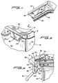
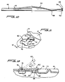
- the major central portion of the cover 14 is formed in a concavo-convex configuration and comprises a central disc 56 peripherally joined with the surrounding portion of the cover by an integral living hinge structure 58 which allows for a flexing of the disc 56 between an inwardly directed convex position, as in Figures 3 and 4 wherein there is little pressure differential between the interior and exterior of the container, and a second outwardly convex position, as in Figures 2 and 10, which will result from a predetermined buildup of internal pressure from the fermentation process.
- the nature of the living hinge and the specific configuration of the flexing disc 56 are such whereby full movement of the disc 56 to its outer or pressure-extended position occurs when the internal generated pressure is consistent with arrival at the desired fermentation level, thereby providing a ready visual indication of the completion of the fermentation without requiring an opening of the container or an exposure of the contents.
- a closure 62 associated with the port 60 includes a handling flap 64 with a depending plug 66 which frictionally engages within and seals the port 60.
- the plug 66 as illustrated, may have a peripherally enlarged leading end to effect a positive snap lock within the port 60.
- the plug is preferably provided with a central downwardly opening conical recess 68 whereby internal pressure generated within the container will also act within the recess and tend to laterally outwardly bias the plug for enhanced sealing engagement within the port 60.
- the rigid flap 64 includes a slightly upwardly bowed edge portion immediately adjacent the plug 66 which defines a finger grip 70.
- the cover 14 immediately outward of the finger grip 70 has a recess 72 defined therein to allow ready access to the finger grip 70 for an upward pivoting of the closure 62 to disengage the plug 66 from the port 60.
- the flap 64 diametrically opposed from the finger grip 72, is hinged to the cover 14 by a transverse pin 74 engaged through aligned knuckles 76 formed from the closure flap 64 and the top panel of the cover.
- a closed chamber 78 is provided immediately below the hinged joinder of the closure 62 to the top panel of the cover 14 to accommodate pivotal movement of the closure flap 64 to its open position, and to allow formation of the hinge assembly without perforation of the cover.
- the handles 16 function alternately as a means for locking the cover 14 to the receptacle 12 during the fermentation process, and as a carrying means for the container upon release from their locking position.
- Each handle 16 includes a pair of opposed arms 80 positioned to the opposite sides of the container 12 and mounting inwardly directed pivot pins 82 engaged within a pair of opposed slots 38 within the mounting flange 36.
- each pivot pin includes an enlarged head on the outer end thereof which passes freely through the enlarged central opening 40 of the slot but which, upon longitudinal shifting of the pin 82 within the slot 38, precludes lateral withdrawal from the slot.
- actual engagement and disengagement of the pins 82 from the slots 38 will require a slight outward flexing of the arms 80 of the handles 16.
- each handle 16 The outer ends of the arms 80 of each handle 16 are integrally interconnected by a crossbar 84 in the nature of a retention or retainer member for the cover as will be apparent subsequently.
- each handle 16 in the downwardly swung position thereof as in Figures 2 and 9 in particular, includes a top panel 86 which overlies the peripheral rim 54 of the cover 14 and which is relatively wider at and extends generally diagonally across the corners defined between the bar 84 and associated arms 80 as generally indicated at reference numeral 88.
- the inner edge of the top panel 86 includes a depending pressure flange 90 which, across the corresponding end of the receptacle, is inwardly spaced from the cover rim 54, but which, at the generally diagonal corners, overlies and engages against the cover rim. This feature will be noted at 92 in Figures 2 and 9.
- each of the retainer bars 84 also includes a pair of spaced transverse pressure ribs 94 integral with the top panel 86 and extending outward from the pressure flange 90 to an outer bulbous portion 96 defining the outer periphery of the top panel 86 of the handle 16.
- the pressure ribs 94 are of a depth so as to overlie and engage on the cover rim 54 centrally along the end wall portion thereof simultaneously with engagement of the corner portions of the associated pressure rib 90 with the cover rim at points 92 located on the side wall portions of the cover in close proximity to the associated end wall portion.
- Each of the handles 16 additionally includes a pair of integral depending locking clips 98 aligned with the corresponding end wall locking lugs 32 and longitudinally spaced along the crossbar 84 so as to pass to the opposite sides of the receptacle hand grip 30.
- Each of the locking clips 98 includes a laterally inwardly directed bottom flange 100 adapted to slidably engage, with a positive friction fit, beneath the bulbous lower edge 34 of the corresponding locking lug 32 upon an inward sliding of the crossbar 84, accommodated by the sliding movement of the pivot pins 82 within the corresponding elongate slots 38 at the inner ends of the corresponding handle arms 80.
- each crossbar 84 in order to provide for a generally parallel positioning of each crossbar 84 over and relative to the cover in the locking position thereof, the corresponding mounting arms 80 have the inner portions thereof angled downwardly to position the corresponding pivot pins 82 below the cover 14 and in alignment with the pin receiving slots 38 in the depending side flanges 36.
- the length of the slots 38 is such that when it is desired to release the clamping pressure on the cover 14, the opposed handles 16 are merely horizontally outwardly shifted, the pivot pins 82 moving easily along the corresponding slots 38.
- the longitudinal spacing of the locking clips 98 is such as to provide a hand grip area therebetween.
- the hand grips 30 extend substantially outward beyond the locking clips 98 for ready access thereto to allow for a carrying of the closed and sealed container.
- the appropriate ingredients are placed within the receptacle 12.
- the cover 14, with the central panel 56 depressed is sealed to the receptacle by frictional engagement of the receptacle sealing flange 28 within the peripheral sealing groove 52 of the cover 14.
- the two handles 16 are then swung outwardly and downwardly to a generally horizontal position with the locking clips 98 in outward alignment with the locking lugs 32.
- the handles 16 are then shifted laterally inward to frictionally engage the lower flanges 100 of the clips 98 with and immediately below the locking lugs 32. So positioned, the pressure flanges 90 and pressure ribs 94 are retained in downward clamping engagement against the rim 54 of the cover.
- the container is then set aside and the fermentation process takes place.
- the fermentation process will create enough pressure within the container to cause the central indicator disc 56 to bulge or dome outwardly, flexing about the peripheral living hinge 58. It is contemplated that this will occur approximately eight days after initiation of the fermentation process, and will provide a positive visual indication that the fermentation process is complete or at least has reached a substantially complete stage.
- the container preferably after removal from the house because of the odiferous nature of the gases, is vented through the venting port 60 by upwardly flipping the closure 62 to disengage the plug 66 from the port.
- the cover can be safely removed and the contents inspected. If, as is normally the case, the fermentation process is completed, nothing further need be done. Should it be decided that more "pickling" is necessary or desired, the central indicator disc 56 of the cover can be downwardly inverted, and the container resealed.
- the components are economically formed, preferably moulded of an appropriate synthetic resinous material, and capable of providing, when closed, a positive gas-tight seal.
- the container described can be easily closed and locked, and equally easily unlocked and opened.
Landscapes
- Engineering & Computer Science (AREA)
- Chemical & Material Sciences (AREA)
- Food Science & Technology (AREA)
- Life Sciences & Earth Sciences (AREA)
- Polymers & Plastics (AREA)
- Wood Science & Technology (AREA)
- Zoology (AREA)
- General Chemical & Material Sciences (AREA)
- Chemical Kinetics & Catalysis (AREA)
- Mechanical Engineering (AREA)
- Closures For Containers (AREA)
- Preparation Of Fruits And Vegetables (AREA)
- Storage Of Fruits Or Vegetables (AREA)
- Control And Other Processes For Unpacking Of Materials (AREA)
- General Preparation And Processing Of Foods (AREA)
- Food-Manufacturing Devices (AREA)
- Cookers (AREA)
Claims (12)
- Un récipient de traitement de produit alimentaire (10) comprenant un réceptacle à ouverture vers le haut (12) et un couvercle (14) monté de façon amovible selon une relation de recouvrement et d'étanchéité par rapport audit réceptable (12); ledit réceptacle (12) comprenant des moyens à paroi périphérique (20), (22) avec des moyens à rebord supérieur périphériques (24), (28) définissant un dessus ouvert audit réceptacle et un fond fermé (18); ledit couvercle (14) comprenant des moyens d'étanchéité périphérique (52) de même dimension et susceptibles de venir au contact avec lesdits moyens à rebord de réceptacle (28) pour étanchéifier ledit couvercle (14) audit réceptacle (12) et des moyens de retenue (84), (98) montés sur ledit réceptacle et mobiles par rapport à celui-ci entre une première position de prise et de serrage dudit couvercle (14) contre ledit réceptacle (12) et une deuxième position de dégagement dudit couvercle pour permettre le retrait dudit couvercle à partir dudit réceptacle, caractérisé en ce que lesdits moyens de retenue (84), (98) comprennent une paire de barres de retenue espacées (84) capables de recouvrir les parties périphériques opposées dudit couvercle (14) chaque barre (84) ayant au moins un clip de blocage pendant (98), lesdits moyens à paroi de réceptacle (20), (22) renfermant des pattes de blocage (32) chacune étant capable d'être alignée avec l'un desdits clips (98) et des moyens (36), (80) de montage de chaque barre de retenue (84) audit réceptacle pour un mouvement horizontal net entre ladite première position dans laquelle ledit clip (98) sur ceux-ci est mis en prise avec la patte associée (32) pour empêcher le mouvement vers le haut dudit couvercle par rapport audit réceptacle et une seconde position dans laquelle ledit clip sur ceux-ci est aligné mais décalé horizontalement à partir de la patte associée pour permettre le mouvement vers le haut dudit couvercle par rapport audit réceptacle, ledit couvercle comportant une partie indicatrice (56) formée sur celui-ci et étant apte à être déplacé en réponse à une augmentation de pression dans ledit réceptacle.
- Le récipient suivant la revendication 1, dans lequel le moyen de montage de chaque barre de retenue (84) comprend une paire de bras espacés latéralement (80) fixés et s'étendant à partir de la barre de retenue (84) et se terminant dans les extrémités intérieures en prise de façon coulissante et pivotante avec lesdits moyens à paroi de réceptacle sur un axe espacé à partir de la barre de retenue et parallèle à celle-ci pour un mouvement de pivotement de la barre de retenue.
- Le récipient suivant la revendication 2, dans lequel ladite partie indicatrice (56) dudit couvercle (14) est mobile sélectivement entre une première position s'étendant vers l'intérieur par rapport audit réceptacle (12) et indiquant l'absence de toute augmentation de pression gazeuse sensible dans ledit récipient (10) et une deuxième position se prolongeant vers l'extérieur par rapport audit réceptacle (12) et indiquant une augmentation de pression gazeuse prédéterminée dans ledit récipient (10).
- Le récipient suivant la revendication 3, dans lequel ladite partie indicatrice (56) présente une configuration concave-convexe avec une articulation active d'un seul tenant (58) reliant à la périphérie ladite partie à la partie environnante dudit couvercle.
- Le récipient suivant la revendication 4, dans lequel ladite partie indicatrice (56) est au repos dans chacune desdites première et deuxième positions de celle-ci et est susceptible de revenir manuellement à partir de ladite deuxième position vers ladite première position lors de la libération de la pression gazeuse accrue sur celle-ci.
- Le récipient suivant la revendication 5, dans lequel ledit couvercle (14) comprend, en outre, un orifice de libération de pression (60) au travers de celui-ci et un moyen de fermeture susceptible d'être dégagé manuellement (62) pour ouvrir sélectivement ledit orifice (60).
- Le récipient suivant la revendication 2 ou la revendication 6, dans lequel ledit moyen à rebord comprend une partie de bord supérieur continue (24) sur lesdits moyens à paroi (20), (22) et une bride d'étanchéité dirigée vers le haut (28) de même dimension avec ladite partie de bord supérieur (24), lesdites pattes de blocage (32) étant solidaires avec lesdits moyens à paroi contigus à ladite partie de bord supérieur (24) et en dessous de ladite bride d'étanchéité (28), lesdites pattes (32) se prolongeant vers le bas et vers l'extérieur par rapport à ladite partie de bord supérieur.
- Le récipient suivant la revendication 7, dans lequel chaque clip de blocage (98) comprend une partie d'extrémité inférieure tournée latéralement (100) susceptible d'être mise en prise par le dessous et par le haut contre la patte de blocage associée (32), ladite partie d'extrémité inférieure (100) étant positionnée par rapport à la barre de retenue associée (84) si bien que cette barre vient en prise sur le dessus et vers le bas contre le couvercle monté (14) simultanément avec la prise de la partie d'extrémité inférieure (100) contre la patte de blocage associée (32) pour un serrage dudit couvercle (14) audit réceptacle (12).
- Le récipient suivant la revendication 8 comprenant une paire de poignées (30) solidaires et se prolongeant vers l'extérieur de zones opposées (20) desdits moyens à paroi contigus à ladite partie de bord supérieur (24).
- Le récipient suivant les revendications 2 et 9, dans lequel lesdits moyens à parois périphériques (20), (22), dudit réceptacle comportent des parois d'extrémité opposées (20) et des parois latérales opposées (22), lesdites pattes de blocage (32) se prolongeant à partir desdites parois d'extrémité (20), lesdits moyens (36), (80) de montage de chaque barre de retenue (84) comprenant, en outre une paire de brides de montage (36), l'une étant solidaire avec chaque paroi latérale (22) selon une relation généralement parallèle espacée vers l'extérieur à partir de celle-ci, chaque bride de montage (36) ayant une paire de fentes alignées espacées (38) définies dans celle-ci, ladite paire de bras espacés (80) de chaque barre de retenue (84) ayant ses extrémités intérieures alignées avec une paire de l'une correspondante desdites fentes (38), l'une dans chaque bride de montage (36) et une tige à pivot (82) fixée à chaque extrémité intérieure de bras, les deux tiges étant retenues de façon coulissante et pivotante dans la fente alignée (38) si bien que chacun de ladite barre de retenue et desdits bras associés est susceptible d'être pivoté vers le haut pour positionner la barre espacée au-dessus et transversalement au niveau du réceptacle et du couvercle et est pivoté vers le bas dans une position généralement horizontale avec les clips de blocage (98) à l'alignement extérieur avec les pattes de blocage (32) de façon à mettre en prise ladite barre sur ledit couvercle et chaque barre de retenue (84) avec les bras associés (80) est, lorsqu'elle est en prise sur ledit couvercle (14) susceptible de coulisser pour sélectivement venir en prise et libérer lesdits clips (98) avec lesdites pattes de blocage (32).
- Le récipient suivant la revendication 10, dans lequel une paire de pattes de blocage (32) se prolonge à partir de chaque paroi d'extrémité (20) dans des points espacés latéralement sur celle-ci, l'une desdites poignées (30) se prolongeant à partir de chaque paroi d'extrémité (20) entre les pattes de blocage correspondantes (32).
- Le récipient suivant la revendication 1, dans lequel ladite partie indicatrice (56) dudit couvercle (14) est mobile sélectivement entre une première position s'étendant vers l'intérieur par rapport audit réceptacle (12) et indiquant l'absence de toute augmentation de pression gazeuse sensible dans ledit récipient (10) et une deuxième position se prolongeant vers l'extérieur par rapport audit réceptacle (12) et indiquant une augmentation de pression gazeuse prédéterminée dans ledit récipient (10), ladite partie indicatrice (56) étant au repos dans chacune desdites première et deuxième positions de celui-ci et étant apte à être ramenée manuellement à partir de ladite deuxième position vers ladite première position lors de la libération de la pression gazeuse accrue sur celui-ci.
Applications Claiming Priority (2)
| Application Number | Priority Date | Filing Date | Title |
|---|---|---|---|
| US983932 | 1992-12-01 | ||
| US07/983,932 US5337910A (en) | 1992-12-01 | 1992-12-01 | Food processing container |
Publications (2)
| Publication Number | Publication Date |
|---|---|
| EP0600323A1 EP0600323A1 (fr) | 1994-06-08 |
| EP0600323B1 true EP0600323B1 (fr) | 1997-10-22 |
Family
ID=25530191
Family Applications (1)
| Application Number | Title | Priority Date | Filing Date |
|---|---|---|---|
| EP93118669A Expired - Lifetime EP0600323B1 (fr) | 1992-12-01 | 1993-11-19 | Récipient de traitement de produit alimentaire |
Country Status (9)
| Country | Link |
|---|---|
| US (1) | US5337910A (fr) |
| EP (1) | EP0600323B1 (fr) |
| JP (1) | JPH07108179B2 (fr) |
| KR (1) | KR960001519B1 (fr) |
| AT (1) | ATE159491T1 (fr) |
| AU (1) | AU5046593A (fr) |
| DE (1) | DE69314752T2 (fr) |
| MY (1) | MY110146A (fr) |
| PH (1) | PH30165A (fr) |
Families Citing this family (49)
| Publication number | Priority date | Publication date | Assignee | Title |
|---|---|---|---|---|
| KR960004757Y1 (ko) * | 1993-10-16 | 1996-06-08 | 장근홍 | 과일상자 |
| US5456164A (en) * | 1995-01-10 | 1995-10-10 | Donghwan Ind. Corp. | Kimchi fermentation or cool storage system using a thermoelectric module |
| US5715968A (en) * | 1996-09-27 | 1998-02-10 | Fink; Stacey M. | Hand carried shopping basket |
| US5878881A (en) * | 1997-06-02 | 1999-03-09 | Hunt; Ricardo | Storage saver system |
| USD403581S (en) * | 1997-07-24 | 1999-01-05 | Berry Plastics Corporation | Container cover |
| USD405014S (en) * | 1997-07-24 | 1999-02-02 | Berry Plastics Corporation | Container |
| US5823345A (en) * | 1997-07-24 | 1998-10-20 | Berry Plastics Corporation | Stackable receptacle assembly for pourable products |
| USD403241S (en) | 1997-07-24 | 1998-12-29 | Olin Corporation | Container cover assembly |
| USD403582S (en) * | 1997-08-22 | 1999-01-05 | Olin Corporation | Container cover assembly |
| US5896993A (en) * | 1997-09-04 | 1999-04-27 | Olin Corporation | Stackable receptacle assembly for pourable products |
| GB2330824A (en) * | 1997-10-29 | 1999-05-05 | Mars Inc | Cashbox handle |
| SE513904C2 (sv) * | 1998-02-12 | 2000-11-27 | Lina Lindberg | Anordning vid varukorg för att åstadkomma ett ergonomiskt fördelaktigt lyft- och transporthandtag |
| US6367651B2 (en) | 1998-12-30 | 2002-04-09 | Dart Industries Inc. | Vented container for produce |
| US7036693B2 (en) | 2001-12-05 | 2006-05-02 | Masterchem Industries Llc | Paint container |
| US20030197014A1 (en) * | 2001-12-05 | 2003-10-23 | Muchin Jay Z. | Paint storage container |
| USD499027S1 (en) | 2002-09-25 | 2004-11-30 | Masterchem Industries, Inc. | Container handle |
| US20040084455A1 (en) * | 2002-11-06 | 2004-05-06 | Haggai Shosheny | Container with peel-off cover |
| CA2531841A1 (fr) * | 2003-07-09 | 2005-01-27 | Masterchem Industries, Llc | Poignee de receptacle de peinture |
| USD496531S1 (en) | 2003-09-11 | 2004-09-28 | Zag Industries Ltd. | Toolbox with handle |
| US6987247B2 (en) * | 2003-12-31 | 2006-01-17 | Salton, Inc. | Portable slow cooker |
| KR100548059B1 (ko) * | 2004-01-08 | 2006-02-09 | 왕수창 | 발효식품용 밀폐용기 |
| US20050279654A1 (en) * | 2004-06-16 | 2005-12-22 | Jorge Robles | Container with corner grips |
| US20060207994A1 (en) * | 2005-03-18 | 2006-09-21 | Superfos A/S | Container with displaceable handle |
| USD528353S1 (en) | 2005-06-16 | 2006-09-19 | Hamilton Beach/Proctor-Silex, Inc. | Slow cooker |
| DE202005013057U1 (de) * | 2005-08-12 | 2006-12-28 | C. & E. Fein Gmbh | Tragbarer Behälter |
| US7485831B2 (en) * | 2006-03-01 | 2009-02-03 | Hamilton Beach Brands, Inc. | Slow cooker |
| KR100987247B1 (ko) * | 2007-05-28 | 2010-10-12 | 씨제이제일제당 (주) | 김치 포장용기 |
| KR100835557B1 (ko) * | 2007-08-16 | 2008-06-09 | 주식회사 장충동왕족발 | 발효 및 숙성기능이 보강된 김치용 저장용기, 이를 이용한김치 숙성방법 및 이에 의해 제조된 김치 |
| CA2715583A1 (fr) * | 2009-09-25 | 2011-03-25 | Ipl Inc. | Contenant avec poignee retractable |
| US9351606B2 (en) | 2011-03-03 | 2016-05-31 | Hamilton Beach Brands, Inc. | Kitchen appliance and method of assembling same |
| US8827101B2 (en) | 2012-05-21 | 2014-09-09 | Hamilton Beach Brands, Inc. | Kitchen appliance and method of using same |
| GB2502326A (en) * | 2012-05-24 | 2013-11-27 | Darren Langston | An apertured cover for a cooking tray |
| US8584894B1 (en) | 2012-06-15 | 2013-11-19 | Hamilton Beach Brands, Inc. | Kitchen appliance and method of using same |
| US9341403B2 (en) | 2012-07-11 | 2016-05-17 | Milwaukee Electric Tool Corporation | Cooler |
| ITPD20120255A1 (it) * | 2012-09-04 | 2014-03-05 | Filmop Srl | Maniglie per secchio di pulizia |
| US9474410B2 (en) | 2012-10-25 | 2016-10-25 | Hamilton Beach Brands, Inc | Kitchen appliance and method of using same |
| KR102040607B1 (ko) * | 2012-10-30 | 2019-11-05 | 엘지전자 주식회사 | 냉장고 |
| US9155132B2 (en) * | 2012-11-16 | 2015-10-06 | Chak Hong Gary CHEUNG | Microwave container |
| CN104276318B (zh) * | 2014-07-11 | 2016-06-15 | 浙江工业大学 | 多功能篮子 |
| US10583973B1 (en) | 2014-12-26 | 2020-03-10 | Amazon Technologies, Inc. | Combination carrying device |
| US10696454B1 (en) * | 2014-12-26 | 2020-06-30 | Amazon Technologies, Inc. | Combination carrying device |
| US10077137B1 (en) | 2015-12-28 | 2018-09-18 | Amazon Technologies, Inc. | Combination carrying device |
| US10106296B2 (en) * | 2016-01-08 | 2018-10-23 | Wki Holding Company, Inc. | Nesting cooking vessels |
| AU2019206569B2 (en) * | 2018-01-10 | 2025-01-02 | Bway Corporation | Container and container lid with built-in brine disc |
| AU2019295420B2 (en) * | 2018-06-29 | 2025-06-05 | Breville Pty Limited | Safety system, a method for selecting an operating mode, and a lid for a kitchen device |
| CN118723307A (zh) * | 2019-06-07 | 2024-10-01 | 米沃奇电动工具公司 | 带有手柄的储存装置 |
| KR102602278B1 (ko) * | 2022-06-16 | 2023-11-16 | 주식회사 원앙 | 캠핑용 다용도 설거지통 키트 |
| US20240051712A1 (en) * | 2022-08-15 | 2024-02-15 | Pure Fishing, Inc. | Collapsible container |
| US11981480B2 (en) * | 2022-10-06 | 2024-05-14 | Dart Industries Inc. | Serving dish cover |
Family Cites Families (23)
| Publication number | Priority date | Publication date | Assignee | Title |
|---|---|---|---|---|
| US1240689A (en) * | 1917-03-10 | 1917-09-18 | Thomas F Durning | Oil-can vent. |
| US1384851A (en) * | 1920-11-06 | 1921-07-19 | George J Richardson | Cover for cooking utensils |
| US2307043A (en) * | 1939-12-05 | 1943-01-05 | American Can Co | Container |
| US2296848A (en) * | 1939-12-16 | 1942-09-29 | American Can Co | Container |
| US2983402A (en) * | 1959-06-29 | 1961-05-09 | Ronald B Gottsegen | Handle for top-covered container |
| US3057508A (en) * | 1960-11-28 | 1962-10-09 | Ideal Fishing Float Company In | Portable cooler |
| US3717276A (en) * | 1971-02-12 | 1973-02-20 | Owens Illinois Inc | Vented closure |
| US3848767A (en) * | 1972-01-12 | 1974-11-19 | Leer Koninklijke Emballage | Container with lid |
| USD243914S (en) | 1975-07-15 | 1977-04-05 | Maruka Shokuhin Kabushiki Kaisha | Container for food or the like |
| US4149650A (en) * | 1975-12-15 | 1979-04-17 | Roger S. Sanderson | Sterilized storage container |
| US4349118A (en) * | 1975-12-15 | 1982-09-14 | Roger S. Sanderson | Sterilizing and storing medical items |
| USD253331S (en) | 1977-06-03 | 1979-11-06 | FKF Fleischwaren- und Konserven-Fabrik, Schultz & Berndt GmbH & Co. KG | Food container |
| USD257930S (en) | 1979-08-16 | 1981-01-20 | Dart Industries Inc. | Closured container or the like |
| US4592482A (en) * | 1980-11-14 | 1986-06-03 | King-Seeley Thermos Co. | Handle mechanism for cooler or the like |
| USD277632S (en) | 1982-02-19 | 1985-02-19 | Rubbermaid Incorporated | Food storage dish |
| US4548824A (en) * | 1983-05-02 | 1985-10-22 | Pakor, Inc. | Package for storing perishable products in a reduced air atmosphere |
| USD302774S (en) | 1986-04-03 | 1989-08-15 | Rubbermaid Incorporated | Storage container |
| US4678082A (en) * | 1986-07-10 | 1987-07-07 | Owens-Illinois, Inc. | Vacuum indicating thermoplastic closure |
| DE8911266U1 (de) * | 1989-03-22 | 1989-11-30 | E. Damberg Group A/S, Nykoebing Falster | Tragbarer Kasten |
| NL8901236A (nl) * | 1989-05-18 | 1990-12-17 | Stamicarbon | Houder voorzien van een afsluitbaar deksel. |
| US5065885A (en) * | 1990-02-09 | 1991-11-19 | Scaroni F.Lli S.P.A. | Airtight container |
| US4989744A (en) * | 1990-02-12 | 1991-02-05 | Kabushiki Kaisha Tominaga Jyushi Kogyosho | Portable container |
| GB9109820D0 (en) * | 1991-05-07 | 1991-06-26 | Courtaulds Coatings Holdings | Lid for a pail |
-
1992
- 1992-12-01 US US07/983,932 patent/US5337910A/en not_active Expired - Fee Related
-
1993
- 1993-10-20 MY MYPI93002164A patent/MY110146A/en unknown
- 1993-10-24 PH PH47318A patent/PH30165A/en unknown
- 1993-11-05 AU AU50465/93A patent/AU5046593A/en not_active Abandoned
- 1993-11-19 EP EP93118669A patent/EP0600323B1/fr not_active Expired - Lifetime
- 1993-11-19 DE DE69314752T patent/DE69314752T2/de not_active Expired - Fee Related
- 1993-11-19 AT AT93118669T patent/ATE159491T1/de active
- 1993-11-30 KR KR1019930025753A patent/KR960001519B1/ko not_active Expired - Lifetime
- 1993-12-01 JP JP30183793A patent/JPH07108179B2/ja not_active Expired - Lifetime
Also Published As
| Publication number | Publication date |
|---|---|
| JPH06209699A (ja) | 1994-08-02 |
| KR940013426A (ko) | 1994-07-15 |
| AU5046593A (en) | 1994-06-23 |
| JPH07108179B2 (ja) | 1995-11-22 |
| EP0600323A1 (fr) | 1994-06-08 |
| PH30165A (en) | 1997-01-21 |
| ATE159491T1 (de) | 1997-11-15 |
| US5337910A (en) | 1994-08-16 |
| DE69314752D1 (de) | 1997-11-27 |
| DE69314752T2 (de) | 1998-02-19 |
| MY110146A (en) | 1998-02-28 |
| KR960001519B1 (ko) | 1996-02-01 |
Similar Documents
| Publication | Publication Date | Title |
|---|---|---|
| EP0600323B1 (fr) | Récipient de traitement de produit alimentaire | |
| US4917261A (en) | Vacuum-formed container with u-shaped lock | |
| US4986438A (en) | Recloseable nesting tab container | |
| US5207345A (en) | Lid adapter for bucket | |
| US2695645A (en) | Bread server or analogous seal tight container | |
| US20030116572A1 (en) | Sealing cover for a container | |
| EP1458620B1 (fr) | Recipient muni d'un couvercle articule | |
| US3520440A (en) | Container and closure therefor | |
| US7080754B2 (en) | Container/hinged lid assembly | |
| US4765506A (en) | Combination storage container and triple seal lid | |
| CA2120866C (fr) | Couvercle etanche avec event | |
| US5718347A (en) | Child resistant, user friendly container and closure | |
| US5607709A (en) | Disposable microwavable food container | |
| US4771934A (en) | Food tray with lid locking mechanism | |
| FI90333C (fi) | Keinuttamalla avautuva kansi | |
| US2765094A (en) | Closure | |
| EP0299734B1 (fr) | Récipients pour boissons | |
| US4969572A (en) | End closure having a push open lid portion | |
| CN110834808B (zh) | 具有盖子的储存容器 | |
| GB2538397A (en) | Ventable storage container and method of use | |
| US3470930A (en) | Container and closure therefor | |
| US5195645A (en) | End closure having adjustable push open lid | |
| JPS60183351A (ja) | 容器の安全密封装置 | |
| USRE34263E (en) | End closure having a push open lid portion | |
| US10435210B1 (en) | Scoop dock and use methods |
Legal Events
| Date | Code | Title | Description |
|---|---|---|---|
| PUAI | Public reference made under article 153(3) epc to a published international application that has entered the european phase |
Free format text: ORIGINAL CODE: 0009012 |
|
| AK | Designated contracting states |
Kind code of ref document: A1 Designated state(s): AT BE CH DE DK ES FR GB GR IE IT LI LU MC NL PT SE |
|
| 17P | Request for examination filed |
Effective date: 19941205 |
|
| 17Q | First examination report despatched |
Effective date: 19951113 |
|
| GRAG | Despatch of communication of intention to grant |
Free format text: ORIGINAL CODE: EPIDOS AGRA |
|
| GRAH | Despatch of communication of intention to grant a patent |
Free format text: ORIGINAL CODE: EPIDOS IGRA |
|
| GRAH | Despatch of communication of intention to grant a patent |
Free format text: ORIGINAL CODE: EPIDOS IGRA |
|
| GRAA | (expected) grant |
Free format text: ORIGINAL CODE: 0009210 |
|
| AK | Designated contracting states |
Kind code of ref document: B1 Designated state(s): AT BE CH DE DK ES FR GB GR IE IT LI LU MC NL PT SE |
|
| PG25 | Lapsed in a contracting state [announced via postgrant information from national office to epo] |
Ref country code: NL Free format text: LAPSE BECAUSE OF FAILURE TO SUBMIT A TRANSLATION OF THE DESCRIPTION OR TO PAY THE FEE WITHIN THE PRESCRIBED TIME-LIMIT Effective date: 19971022 Ref country code: LI Free format text: LAPSE BECAUSE OF FAILURE TO SUBMIT A TRANSLATION OF THE DESCRIPTION OR TO PAY THE FEE WITHIN THE PRESCRIBED TIME-LIMIT Effective date: 19971022 Ref country code: IT Free format text: LAPSE BECAUSE OF FAILURE TO SUBMIT A TRANSLATION OF THE DESCRIPTION OR TO PAY THE FEE WITHIN THE PRE;WARNING: LAPSES OF ITALIAN PATENTS WITH EFFECTIVE DATE BEFORE 2007 MAY HAVE OCCURRED AT ANY TIME BEFORE 2007. THE CORRECT EFFECTIVE DATE MAY BE DIFFERENT FROM THE ONE RECORDED.SCRIBED TIME-LIMIT Effective date: 19971022 Ref country code: GR Free format text: LAPSE BECAUSE OF FAILURE TO SUBMIT A TRANSLATION OF THE DESCRIPTION OR TO PAY THE FEE WITHIN THE PRESCRIBED TIME-LIMIT Effective date: 19971022 Ref country code: ES Free format text: THE PATENT HAS BEEN ANNULLED BY A DECISION OF A NATIONAL AUTHORITY Effective date: 19971022 Ref country code: DK Free format text: LAPSE BECAUSE OF NON-PAYMENT OF DUE FEES Effective date: 19971022 Ref country code: CH Free format text: LAPSE BECAUSE OF FAILURE TO SUBMIT A TRANSLATION OF THE DESCRIPTION OR TO PAY THE FEE WITHIN THE PRESCRIBED TIME-LIMIT Effective date: 19971022 Ref country code: BE Free format text: LAPSE BECAUSE OF FAILURE TO SUBMIT A TRANSLATION OF THE DESCRIPTION OR TO PAY THE FEE WITHIN THE PRESCRIBED TIME-LIMIT Effective date: 19971022 Ref country code: AT Free format text: LAPSE BECAUSE OF FAILURE TO SUBMIT A TRANSLATION OF THE DESCRIPTION OR TO PAY THE FEE WITHIN THE PRESCRIBED TIME-LIMIT Effective date: 19971022 |
|
| REF | Corresponds to: |
Ref document number: 159491 Country of ref document: AT Date of ref document: 19971115 Kind code of ref document: T |
|
| REG | Reference to a national code |
Ref country code: CH Ref legal event code: EP |
|
| PG25 | Lapsed in a contracting state [announced via postgrant information from national office to epo] |
Ref country code: LU Free format text: LAPSE BECAUSE OF NON-PAYMENT OF DUE FEES Effective date: 19971119 |
|
| REF | Corresponds to: |
Ref document number: 69314752 Country of ref document: DE Date of ref document: 19971127 |
|
| PG25 | Lapsed in a contracting state [announced via postgrant information from national office to epo] |
Ref country code: IE Free format text: LAPSE BECAUSE OF NON-PAYMENT OF DUE FEES Effective date: 19971222 |
|
| PG25 | Lapsed in a contracting state [announced via postgrant information from national office to epo] |
Ref country code: SE Effective date: 19980122 Ref country code: PT Free format text: LAPSE BECAUSE OF FAILURE TO SUBMIT A TRANSLATION OF THE DESCRIPTION OR TO PAY THE FEE WITHIN THE PRESCRIBED TIME-LIMIT Effective date: 19980122 |
|
| ET | Fr: translation filed | ||
| NLV1 | Nl: lapsed or annulled due to failure to fulfill the requirements of art. 29p and 29m of the patents act | ||
| REG | Reference to a national code |
Ref country code: CH Ref legal event code: PL |
|
| PG25 | Lapsed in a contracting state [announced via postgrant information from national office to epo] |
Ref country code: MC Free format text: LAPSE BECAUSE OF NON-PAYMENT OF DUE FEES Effective date: 19980531 |
|
| PLBE | No opposition filed within time limit |
Free format text: ORIGINAL CODE: 0009261 |
|
| STAA | Information on the status of an ep patent application or granted ep patent |
Free format text: STATUS: NO OPPOSITION FILED WITHIN TIME LIMIT |
|
| 26N | No opposition filed | ||
| PGFP | Annual fee paid to national office [announced via postgrant information from national office to epo] |
Ref country code: FR Payment date: 19981016 Year of fee payment: 6 |
|
| PGFP | Annual fee paid to national office [announced via postgrant information from national office to epo] |
Ref country code: GB Payment date: 19981120 Year of fee payment: 6 |
|
| PGFP | Annual fee paid to national office [announced via postgrant information from national office to epo] |
Ref country code: DE Payment date: 19990111 Year of fee payment: 6 |
|
| PG25 | Lapsed in a contracting state [announced via postgrant information from national office to epo] |
Ref country code: GB Free format text: LAPSE BECAUSE OF NON-PAYMENT OF DUE FEES Effective date: 19991119 |
|
| GBPC | Gb: european patent ceased through non-payment of renewal fee |
Effective date: 19991119 |
|
| PG25 | Lapsed in a contracting state [announced via postgrant information from national office to epo] |
Ref country code: FR Free format text: LAPSE BECAUSE OF NON-PAYMENT OF DUE FEES Effective date: 20000731 |
|
| PG25 | Lapsed in a contracting state [announced via postgrant information from national office to epo] |
Ref country code: DE Free format text: LAPSE BECAUSE OF NON-PAYMENT OF DUE FEES Effective date: 20000901 |
|
| REG | Reference to a national code |
Ref country code: FR Ref legal event code: ST |