EP0600363B1 - Elektrisches Schaginstrument mit einem auf einem Vibration übertragenden Träger befestigten Vibrationsdetektor - Google Patents
Elektrisches Schaginstrument mit einem auf einem Vibration übertragenden Träger befestigten Vibrationsdetektor Download PDFInfo
- Publication number
- EP0600363B1 EP0600363B1 EP93118918A EP93118918A EP0600363B1 EP 0600363 B1 EP0600363 B1 EP 0600363B1 EP 93118918 A EP93118918 A EP 93118918A EP 93118918 A EP93118918 A EP 93118918A EP 0600363 B1 EP0600363 B1 EP 0600363B1
- Authority
- EP
- European Patent Office
- Prior art keywords
- vibration
- vibrations
- percussion instrument
- sensor board
- sensor
- Prior art date
- Legal status (The legal status is an assumption and is not a legal conclusion. Google has not performed a legal analysis and makes no representation as to the accuracy of the status listed.)
- Expired - Lifetime
Links
Images


Classifications
-
- G—PHYSICS
- G10—MUSICAL INSTRUMENTS; ACOUSTICS
- G10H—ELECTROPHONIC MUSICAL INSTRUMENTS; INSTRUMENTS IN WHICH THE TONES ARE GENERATED BY ELECTROMECHANICAL MEANS OR ELECTRONIC GENERATORS, OR IN WHICH THE TONES ARE SYNTHESISED FROM A DATA STORE
- G10H3/00—Instruments in which the tones are generated by electromechanical means
- G10H3/12—Instruments in which the tones are generated by electromechanical means using mechanical resonant generators, e.g. strings or percussive instruments, the tones of which are picked up by electromechanical transducers, the electrical signals being further manipulated or amplified and subsequently converted to sound by a loudspeaker or equivalent instrument
- G10H3/14—Instruments in which the tones are generated by electromechanical means using mechanical resonant generators, e.g. strings or percussive instruments, the tones of which are picked up by electromechanical transducers, the electrical signals being further manipulated or amplified and subsequently converted to sound by a loudspeaker or equivalent instrument using mechanically actuated vibrators with pick-up means
- G10H3/146—Instruments in which the tones are generated by electromechanical means using mechanical resonant generators, e.g. strings or percussive instruments, the tones of which are picked up by electromechanical transducers, the electrical signals being further manipulated or amplified and subsequently converted to sound by a loudspeaker or equivalent instrument using mechanically actuated vibrators with pick-up means using a membrane, e.g. a drum; Pick-up means for vibrating surfaces, e.g. housing of an instrument
-
- G—PHYSICS
- G10—MUSICAL INSTRUMENTS; ACOUSTICS
- G10D—STRINGED MUSICAL INSTRUMENTS; WIND MUSICAL INSTRUMENTS; ACCORDIONS OR CONCERTINAS; PERCUSSION MUSICAL INSTRUMENTS; AEOLIAN HARPS; SINGING-FLAME MUSICAL INSTRUMENTS; MUSICAL INSTRUMENTS NOT OTHERWISE PROVIDED FOR
- G10D13/00—Percussion musical instruments; Details or accessories therefor
- G10D13/01—General design of percussion musical instruments
- G10D13/02—Drums; Tambourines with drumheads
-
- G—PHYSICS
- G10—MUSICAL INSTRUMENTS; ACOUSTICS
- G10D—STRINGED MUSICAL INSTRUMENTS; WIND MUSICAL INSTRUMENTS; ACCORDIONS OR CONCERTINAS; PERCUSSION MUSICAL INSTRUMENTS; AEOLIAN HARPS; SINGING-FLAME MUSICAL INSTRUMENTS; MUSICAL INSTRUMENTS NOT OTHERWISE PROVIDED FOR
- G10D13/00—Percussion musical instruments; Details or accessories therefor
- G10D13/10—Details of, or accessories for, percussion musical instruments
- G10D13/26—Mechanical details of electronic drums
-
- G—PHYSICS
- G10—MUSICAL INSTRUMENTS; ACOUSTICS
- G10H—ELECTROPHONIC MUSICAL INSTRUMENTS; INSTRUMENTS IN WHICH THE TONES ARE GENERATED BY ELECTROMECHANICAL MEANS OR ELECTRONIC GENERATORS, OR IN WHICH THE TONES ARE SYNTHESISED FROM A DATA STORE
- G10H2220/00—Input/output interfacing specifically adapted for electrophonic musical tools or instruments
- G10H2220/461—Transducers, i.e. details, positioning or use of assemblies to detect and convert mechanical vibrations or mechanical strains into an electrical signal, e.g. audio, trigger or control signal
- G10H2220/525—Piezoelectric transducers for vibration sensing or vibration excitation in the audio range; Piezoelectric strain sensing, e.g. as key velocity sensor; Piezoelectric actuators, e.g. key actuation in response to a control voltage
-
- G—PHYSICS
- G10—MUSICAL INSTRUMENTS; ACOUSTICS
- G10H—ELECTROPHONIC MUSICAL INSTRUMENTS; INSTRUMENTS IN WHICH THE TONES ARE GENERATED BY ELECTROMECHANICAL MEANS OR ELECTRONIC GENERATORS, OR IN WHICH THE TONES ARE SYNTHESISED FROM A DATA STORE
- G10H2230/00—General physical, ergonomic or hardware implementation of electrophonic musical tools or instruments, e.g. shape or architecture
- G10H2230/045—Special instrument [spint], i.e. mimicking the ergonomy, shape, sound or other characteristic of a specific acoustic musical instrument category
- G10H2230/251—Spint percussion, i.e. mimicking percussion instruments; Electrophonic musical instruments with percussion instrument features; Electrophonic aspects of acoustic percussion instruments or MIDI-like control therefor
- G10H2230/275—Spint drum
Definitions
- This invention relates to an electric percussion instrument and, more particularly, to an electric percussion instrument equipped with a vibration sensor supported by a retainer of vibration-transmissive substance.
- a typical example of the electric percussion instrument is disclosed in Japanese Utility Model Publication of Unexamined Application No. 59-39753, and comprises a tubular member with an inner space, heads covering both ends of the tubular member and a cushion member of porous substance such as sponge filling the inner space and a vibration sensor of a piezo-electric element embedded in the cushion member.
- the vibration sensor is adjusted to a center of the inner space, and the cushion member is expected to isolate the vibration sensor from forced vibrations of the tubular member.
- the vibration sensor In a performance, while a player is beating the head, not only the head but also the tubular member vibrate at respective characteristic frequencies, and the cushion member takes up the forced vibrations of the tubular. As a result, the vibration sensor is expected to detect the vibrations of the head.
- the vibration sensor produces an electric signal indicative of the vibrations of the head, and a speaker system reproduces the sound from the electric signal.
- the cushion member takes up not only the vibrations of the tubular member but also the vibrations of the head, and the vibrations at a soft beat are too weak to be detected by the vibration sensors. This means that soft beats are liable to be lost in the reproduction of the sounds.
- GB-A-2 192 087 discloses an electronic drum having a cushioning member located within a case member.
- the cushioning member elastically supports a cushioning/vibration composite plate retaining a sensor.
- the cushioning/vibration composite plate consists of an upper cushioning rubber sheet and a lower cushioning rubber sheet and damps the strike force applied. Since the cushioning/vibration composite plate is a composite plate the cushioning layers cannot be adjusted depending upon the magnitude of impacts exerted on the drum head or pad. This means that soft beats are likely to be lost in the reproduction of the sounds.
- FR-A-2 544 115 discloses an electric percussion instrument avoiding the pick up of noise from the envirement.
- the electric musical instrument comprises a case member, a pad member, a sensor retained by a retainer and a cushion means. If a player beats the pad member softly at a rather peripheral portion the sound production may be lost easily.
- FR-A-2 602 607 refers to an acusto-electrophonic musical instrument having a retainer, carrying a sensor and comprising a plurality of stud members fixed to a pad member and a sensor board fixed to said plurality of stud members and supporting said vibration sensor. If a player beats the pad member softly at a rather peripheral portion the sound production may be lost easily.
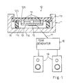
- an electric percussion system is comprises a case member 11, a pad member 12, a sensor board 13, a plurality of stud members 14, a piezo-electric element 15 and a cushion member 16.
- the sensor board 13 and the plurality of stud members 14 as a whole constitute a retainer, and the piezo-electric element 15 serves as a vibration sensor.
- the case member 11 has a bottom portion 11a and a wall portion 11b merged with the bottom portion 11a, and, accordingly, the case member 11 forms a hollow space 11c therein.
- the pad member 12 is implemented by a pad plate 12a formed of iron and partially covered with rubber.
- the rubber film 12b protects an upper surface of the pad plate 12a against impacts at beats by a player, and exposes a central area of the back surface of the pad plate 12a.
- the sensor board 13 is formed of a vibration-transmissive substance selected from the group consisting of iron and acrylonitrile-butadiene-styrene resin, and is fixed to the exposed central area of the back surface of the pad plate 12 by means of the plurality of stud members 14.
- the plurality of stud members 14 are also formed of the vibration-transmissive substance, i.e, either iron or acrylonitrile-butadiene-styrene resin, and the plurality of stud members 14 and the sensor board 12a well propagate vibrations produced in the pad plate 12a to the piezo-electric element 15.
- the plurality of stud members 14 are connected between the exposed area of the pad plate 12a and a peripheral area of the sensor board 13 as shown in Fig. 2, and may be fixed to predetermined locations on the sensor board 13 where the nodes of composite vibrations take place.
- Each of the plurality of stud members 14 is angularly spaced apart from the adjacent stud members by a predetermined angle, and the predetermined angle is 90 degrees in this instance.
- the piezo-electric element 15 is fixed to a central area of the sensor board 13 as shown in Fig. 3, and is equally spaced from the plurality of stud members 14 in the peripheral area of the sensor board 13.
- the central area of the sensor board 13 is less affected by the interference between the vibrations propagated through the plurality of stud members 14, and the piezo-electric element 15 can produces an electric signal exactly indicative of the vibrations produced in the pad plate 12a. Further, the electric signal do not vary its level substantially with an identical beating at a different beaten point over the pad member. Because, the difference in the effective length of the propagation path is rather small.
- the piezo-electric element 15 is connected through wires 17 with a tone generator system 18, and the tone generator system drives a speaker system 19 so as to appropriately produce sounds indicated by the vibrations of the pad plate 12a.
- the cushion member 16 is shaped in a tubular configuration, and is formed of urethane foam.
- the cushion member 16 of urethane foam is effective against a noise produced in the case member 11, and isolates the piezo-electric element 15 from the noise.
- the pad plate 12a, the stud members 14 and the sensor board 13 are fixed in a following manner.
- the stud members 14 of acrylonitrile-butadiene-styrene resin are either bolted or bonded to the pad plate 12a, and the sensor board 13 is either bolted or bonded to the stud members 14.
- the stud members 14 of iron are welded or bolted to the pad plate 12a, and the sensor board 13 of acrylonitrile-butadiene-styrene resin is either bolted or bonded to the stud members 14.
- the stud members 14 of acrylonitrile-butadiene-styrene resin are either bonded or bolted to the pad plate 12a as well as to the sensor board 13.
- the stud members 14 of iron are either welded or bolted to the pad plate as well as the sensor board 12a of iron.
- the player beats the pad member 12, and vibrations are propagated from the beaten point over the pad member 12.
- the pad member 12 and the case member 11 are isolated from each other by means of the cushion member 16, and the pad member 12 is free from a noise produced in the case member 11, if any.
- the stud members 14 propagate the vibrations of the pad member 12 to the sensor board 13, and accelerates the sensor board 13. Then, vibrations take place in the sensor board, and the piezo-electric element 15 produces the electric signal from the vibrations.
- the electric signal is transferred to the tone generator system 18 for electronically synthesizing sound signals, and the sound signals are transferred to the speaker system 19 for producing sounds.
- the stud members 14 are arranged in such a manner as to allow the sensor board 13 to freely vibrate, and faithfully reproduce the vibrations of the pad plate 12a.
- an electric percussion instrument embodying the present invention comprises a case member 21, a pad member 22, a sensor board 23, a plurality of damping members 24, a piezo-electric element 25, a cushion member 26 and adhesive sheets 27.
- the sensor board 13 serves as a retainer
- the piezo-electric element 15 serves as a vibration sensor.
- the case member 21 has a bottom portion 21a and a wall portion 21b merged with the bottom portion 21a, and, accordingly, the case member 21 forms a hollow space 21c therein.
- the pad member 22 is implemented by a pad plate 22a partially covered with a rubber film 22b.
- the pad plate 22a is formed of iron, and is 1.0 millimeter in thickness.
- the rubber film 22b protects an upper surface of the pad plate 22a against strong impacts at beats by a player, and exposes a central area of the back surface of the pad plate 22a.
- the sensor board 33 is formed of a vibration-transmissive substance selected from the group consisting of iron and acrylonitrile-butadiene-styrene resin.
- a vibration-transmissive substance selected from the group consisting of iron and acrylonitrile-butadiene-styrene resin.
- the damping members 24 are bonded between the exposed area of the pad plate 22a and four corner areas of the sensor board 23 by means of the adhesive sheets 27.
- the damping members 24 are formed of porous material such as, for example, cellular polyethylene, and each measures 20 millimeters by 20 millimeters. In this instance, the thickness of the damping members 24 is 1.2 millimeters.
- the damping members 24 thus inserted between the pad plate 22a and the sensor board 23 appropriately damp the vibrations of the pad plate 22a, and causes the vibrations of the sensor board 23 to be fallen into the detectable range of the piezo-electric element 25. For this reason, the damping members 24 are changed to appropriate dimensions depending upon the expected range of impacts, and the thickness of the damping members 24 ranges from 1.0 millimeter to 10 millimeters. If an electric percussion instrument according to the present invention is of a kicked pad, the damping members 24 are changed to be 10 millimeters in thickness, and measure 60 millimeters by 10 millimeters, by way of example.
- the damping members 24 regulates the propagation of the vibrations.
- the vibrations are diffused from the impact point toward the damping members 24, and a time lug tends to be introduced between an arrival time at one of the damping members 24 and an arrival time at another damping member 24.
- the time lugs introduce phase differences between the vibrations propagated to the sensor board 23, and undesirably modify the composite vibrations produced in the sensor board 23.
- the damping members 24 take up the time lugs, and faithfully produce the vibrations in the sensor board 23.
- the piezo-electric element 25 is fixed to a central area of the sensor board 23, and is equally spaced from the plurality of damping members 24 at the corner areas of the sensor board 23.
- the central area of the sensor board 23 is less affected by the interference between the vibrations propagated through the plurality of damping members 24, and the piezo-electric element 25 can produce an electric signal exactly indicative of the vibrations produced in the pad plate 22a.
- the piezo-electric element 25 is connected through wires 28 with a tone generator system as similar to the one described with respect to Fig. 1, and the tone generator system drives a speaker system so as to produce sounds indicated by the vibrations of the pad plate 12a.
- the cushion member 26 is shaped in a tubular configuration, and is formed of urethane foam.
- the cushion member 26 of urethane foam is effective against a noise produced in the case member 21, and isolates the piezo-electric element 25 from the noise.
- the electric percussion instrument according to the present invention achieves not only the goals of the first embodiment but also appropriately regulates the vibrations of the sensor board to the detectable range of the piezo-electric element 25 by means of the damping members 24.
- the vibration sensor may be implemented by any displacement-to-electric signal converter such as, for example, a semiconductor acceleration sensor with a Wheatstone bridge circuit, and the electric percussion instrument according to the present invention may be connected with an amplifier system.
Landscapes
- Physics & Mathematics (AREA)
- Engineering & Computer Science (AREA)
- Acoustics & Sound (AREA)
- Multimedia (AREA)
- Electrophonic Musical Instruments (AREA)
Claims (5)
- Elektrisches Schlaginstrument, das folgendes aufweist:dadurch gekennzeichnet, daßein Gehäuseteil (11; 21), das bei Einwirkung einer Kraft schwingt;ein Schlagflächenteil (12; 22) zur Erzeugung von Schwingungen, wenn ein Spieler auf das elektrische Schlaginstrument schlägt;einen Vibrationssensor (15; 25), der die Schwingungen nachweist zur Erzeugung eines für diese Schwingungen kennzeichnenden elektrischen Signals;Polstermittel (16; 26), die zwischen dem Gehäuseteil (11; 21) und dem Schlagflächenteil (12; 22) vorgesehen sind zur Abschirmung des Vibrationssensors gegen ein in dem Gehäuseteil erzeugtes Geräusch;einen Halter (13/14; 23), der den Vibrationssensor trägt und aus einem Schwingungen übertragenden Material gebildet ist, um die Schwingungen von dem Schlagfächenteil auf den Vibrationssensor zu leiten; undDämpfungsmittel (24), die zwischen dem Schlagflächenteil (22) und dem Halter (23) eine Verbindung herstellen, um die Schwingungen des Halters auf einen nachweisbaren Bereich für den Vibrationssensors einzustellen,
die Abmessungen der Dämpfungsmittel (24) veränderbar sind in Abhängigkeit der erwarteten Stärke der Schläge, die auf das Schlagflächenteil ausgeübt werden. - Elektrisches Schlaginstrument gemäß Anspruch 1, bei dem die Dämpfungsmittel (24) in einer Vielzahl von Dämpfungselementen aus einem porösem Material ausgeführt sind, und der Halter (23) aus einer Sensorplatte aus einem Schwingungen übertragenden Material gefertigt ist, das aus der aus Eisen und Acrylonitril-Butadien-Styrol-Harz bestehenden Gruppe gewählt ist.
- Elektrisches Schlaginstrument gemäß Anspruch 1, bei dem der Halter (13/14) eine Vielzahl von Stiftelementen (14), die an dem Schlagflächenteil befestigt sind, und eine Sensorplatte (13) aufweist, die an der Vielzahl der Stiftelemente befestigt ist und den Vibrationssensor trägt.
- Elektrisches Schlaginstrument gemäß Anspruch 3, bei dem die Vielzahl der Stiftelemente (14) aus einem Schwingungen übertragenden Material gebildet ist, das aus der aus Eisen und Acrylonitril-Butadien-Styrol-Harz bestehenden Gruppe gewählt ist, und die Sensorplatte (13) aus einem Schwingungen übertragenden Material gebildet ist, das aus der aus Eisen und Acrylonitril-Butadien-Styrol-Harz bestehenden Gruppe gewählt ist.
- Elektrisches Schlaginstrument gemäß Anspruch 3, bei dem die Vielzahl der Stiftelemente (14) winkelmäßig voneinander in einem vorgegebenen Winkel in einem peripheralen Bereich der Sensorplatte (13) beabstandet sind, und der Vibrationssensor (15) in einem zentralen Bereich der Sensorplatte (13) von der Vielzahl der Stiftelemente in einer vorgegebenen Entfernung radial beabstandet befestigt ist.
Applications Claiming Priority (4)
| Application Number | Priority Date | Filing Date | Title |
|---|---|---|---|
| JP32213692 | 1992-12-01 | ||
| JP322136/92 | 1992-12-01 | ||
| JP83661/93 | 1993-04-09 | ||
| JP05083661A JP3099580B2 (ja) | 1992-12-01 | 1993-04-09 | 電子ドラム |
Publications (3)
| Publication Number | Publication Date |
|---|---|
| EP0600363A2 EP0600363A2 (de) | 1994-06-08 |
| EP0600363A3 EP0600363A3 (en) | 1994-07-27 |
| EP0600363B1 true EP0600363B1 (de) | 1998-01-28 |
Family
ID=26424697
Family Applications (1)
| Application Number | Title | Priority Date | Filing Date |
|---|---|---|---|
| EP93118918A Expired - Lifetime EP0600363B1 (de) | 1992-12-01 | 1993-11-24 | Elektrisches Schaginstrument mit einem auf einem Vibration übertragenden Träger befestigten Vibrationsdetektor |
Country Status (4)
| Country | Link |
|---|---|
| US (1) | US5396024A (de) |
| EP (1) | EP0600363B1 (de) |
| JP (1) | JP3099580B2 (de) |
| DE (1) | DE69316718T2 (de) |
Families Citing this family (18)
| Publication number | Priority date | Publication date | Assignee | Title |
|---|---|---|---|---|
| JP2850836B2 (ja) * | 1996-03-12 | 1999-01-27 | ヤマハ株式会社 | 電子ドラムパッド |
| JP3228133B2 (ja) * | 1996-07-16 | 2001-11-12 | ヤマハ株式会社 | テーブル型電子打楽器 |
| GB2335779A (en) * | 1998-03-26 | 1999-09-29 | Gary James Parish | Percussion instrument electronic simulation equipment |
| US6326539B1 (en) * | 1998-06-30 | 2001-12-04 | Yamaha Corporation | Musical tone control apparatus and sensing device for electronic musical instrument |
| KR100343229B1 (ko) * | 2000-06-23 | 2002-07-05 | 유현철 | 드럼악기 연주장치 |
| DE10333457B4 (de) * | 2003-07-22 | 2005-12-15 | Franz Puschner | Elektronische Trommel und Nachrüstsatz für herkömmliche elektronische Schlagzeuge |
| US20070052414A1 (en) * | 2005-09-07 | 2007-03-08 | Venegas Innovative Products, Llc | Monitoring platform |
| JP4556894B2 (ja) * | 2006-03-23 | 2010-10-06 | ヤマハ株式会社 | 電子打楽器装置 |
| JP5329109B2 (ja) * | 2008-03-13 | 2013-10-30 | ヤマハ株式会社 | 電子打楽器 |
| US8563843B1 (en) | 2010-01-13 | 2013-10-22 | Guy Shemesh | Electronic percussion device and method |
| US8841527B2 (en) * | 2012-09-12 | 2014-09-23 | Al-Musics Technology Inc. | Electric drum and cymbal with spider web-like sensor |
| JP6652157B2 (ja) * | 2013-03-12 | 2020-02-19 | ヤマハ株式会社 | 電子打楽器 |
| JP6372104B2 (ja) * | 2013-03-12 | 2018-08-15 | ヤマハ株式会社 | 電子打楽器 |
| US9053694B2 (en) * | 2013-03-12 | 2015-06-09 | Yamaha Corporation | Electronic percussion instrument |
| US9424827B2 (en) * | 2014-04-14 | 2016-08-23 | Inmusic Brands, Inc. | Electronic percussion instrument with enhanced playing area |
| KR101598588B1 (ko) * | 2015-08-11 | 2016-02-29 | 주식회사 다음에너지 | 압전소자를 이용한 차량의 자체 속도 감지장치 및 그 감지방법 |
| CN107204179B (zh) * | 2017-06-29 | 2020-11-24 | 得理乐器(珠海)有限公司 | 一种电子鼓鼓边信号检测装置 |
| GB2599670A (en) * | 2020-10-08 | 2022-04-13 | Bhamra Kuljit | Electronic percussion instrument |
Family Cites Families (10)
| Publication number | Priority date | Publication date | Assignee | Title |
|---|---|---|---|---|
| JPS5939753A (ja) * | 1982-08-25 | 1984-03-05 | 旭化成株式会社 | 発泡性耐火被覆材工法 |
| FR2544115A1 (fr) * | 1983-04-08 | 1984-10-12 | Flachier Bernard | Batterie d'entrainement evitant les nuisances sonores |
| US4669349A (en) * | 1984-07-05 | 1987-06-02 | Nippon Gakki Seizo Kabushiki Kaisha | Electronic drum having a closed air space |
| WO1986004718A1 (en) * | 1985-02-06 | 1986-08-14 | Simmons Electronics Ltd. | A pickup arrangement for an electronic percussion instrument |
| JPS61251900A (ja) * | 1985-05-01 | 1986-11-08 | ヤマハ株式会社 | 電子ドラム |
| JPS636494U (de) * | 1986-06-30 | 1988-01-16 | ||
| FR2602607B1 (fr) * | 1986-08-08 | 1993-01-22 | Tatoni Serge | Instrument de musique acousto-electrophonique |
| JPH0738953Y2 (ja) * | 1986-10-23 | 1995-09-06 | ヤマハ株式会社 | 電子バスドラム |
| US5105710A (en) * | 1991-09-16 | 1992-04-21 | Steven Rothmel | Tuned electronic drum pad |
| US5293000A (en) * | 1992-08-25 | 1994-03-08 | Adinolfi Alfonso M | Electronic percussion system simulating play and response of acoustical drum |
-
1993
- 1993-04-09 JP JP05083661A patent/JP3099580B2/ja not_active Expired - Fee Related
- 1993-11-24 DE DE69316718T patent/DE69316718T2/de not_active Expired - Fee Related
- 1993-11-24 EP EP93118918A patent/EP0600363B1/de not_active Expired - Lifetime
- 1993-11-30 US US08/160,041 patent/US5396024A/en not_active Expired - Lifetime
Also Published As
| Publication number | Publication date |
|---|---|
| US5396024A (en) | 1995-03-07 |
| EP0600363A2 (de) | 1994-06-08 |
| JPH06222775A (ja) | 1994-08-12 |
| DE69316718T2 (de) | 1998-07-16 |
| EP0600363A3 (en) | 1994-07-27 |
| DE69316718D1 (de) | 1998-03-05 |
| JP3099580B2 (ja) | 2000-10-16 |
Similar Documents
| Publication | Publication Date | Title |
|---|---|---|
| US5396024A (en) | Electric percussion instrument equipped with vibration sensor supported by retainer of vibration-transmissive substance | |
| US5293000A (en) | Electronic percussion system simulating play and response of acoustical drum | |
| US4669349A (en) | Electronic drum having a closed air space | |
| JPH043357Y2 (de) | ||
| CN100463048C (zh) | 打击垫、无声打击乐器、无声打击乐器组及电子打击系统 | |
| JPH043356Y2 (de) | ||
| JP3933566B2 (ja) | 電子打楽器および振動検出装置 | |
| US6784352B2 (en) | Drumhead and muting structure for acoustic and electronic percussion instruments | |
| US6881885B2 (en) | Electronic pad with vibration isolation features | |
| US5123326A (en) | String musical instrument with tone engendering structures | |
| US5811709A (en) | Acoustic drum with electronic trigger sensor | |
| US4700602A (en) | Electronic drum | |
| US5056403A (en) | Electronic drum with vibration isolating head | |
| JPH0218256B2 (de) | ||
| EP0855698B1 (de) | Elektronische Zimbel | |
| US5837915A (en) | Electronic drum having flat sound producing characteristics | |
| US5854436A (en) | Percussion pads | |
| JP4132170B2 (ja) | 打面装置および電子打楽器 | |
| GB2170639A (en) | Electronic Percussion Instrument | |
| JPH06175651A (ja) | 電子ドラム | |
| JPH09247779A (ja) | 加振装置及び音響装置 | |
| JP2570511B2 (ja) | 発音体支持機構 | |
| JPS62218995A (ja) | 電子打楽器用パツド | |
| US4504967A (en) | Method and apparatus for damping spurious vibration in spring reverberation units | |
| WO2023127128A1 (ja) | 打楽器および打楽器の音量の減音方法 |
Legal Events
| Date | Code | Title | Description |
|---|---|---|---|
| PUAI | Public reference made under article 153(3) epc to a published international application that has entered the european phase |
Free format text: ORIGINAL CODE: 0009012 |
|
| 17P | Request for examination filed |
Effective date: 19931124 |
|
| AK | Designated contracting states |
Kind code of ref document: A2 Designated state(s): DE FR GB IT |
|
| PUAL | Search report despatched |
Free format text: ORIGINAL CODE: 0009013 |
|
| AK | Designated contracting states |
Kind code of ref document: A3 Designated state(s): DE FR GB IT |
|
| 17Q | First examination report despatched |
Effective date: 19961018 |
|
| GRAG | Despatch of communication of intention to grant |
Free format text: ORIGINAL CODE: EPIDOS AGRA |
|
| GRAG | Despatch of communication of intention to grant |
Free format text: ORIGINAL CODE: EPIDOS AGRA |
|
| GRAH | Despatch of communication of intention to grant a patent |
Free format text: ORIGINAL CODE: EPIDOS IGRA |
|
| GRAH | Despatch of communication of intention to grant a patent |
Free format text: ORIGINAL CODE: EPIDOS IGRA |
|
| GRAH | Despatch of communication of intention to grant a patent |
Free format text: ORIGINAL CODE: EPIDOS IGRA |
|
| GRAA | (expected) grant |
Free format text: ORIGINAL CODE: 0009210 |
|
| AK | Designated contracting states |
Kind code of ref document: B1 Designated state(s): DE FR GB IT |
|
| ITF | It: translation for a ep patent filed | ||
| REF | Corresponds to: |
Ref document number: 69316718 Country of ref document: DE Date of ref document: 19980305 |
|
| ET | Fr: translation filed | ||
| PGFP | Annual fee paid to national office [announced via postgrant information from national office to epo] |
Ref country code: FR Payment date: 19981110 Year of fee payment: 6 |
|
| PGFP | Annual fee paid to national office [announced via postgrant information from national office to epo] |
Ref country code: GB Payment date: 19981127 Year of fee payment: 6 |
|
| PLBE | No opposition filed within time limit |
Free format text: ORIGINAL CODE: 0009261 |
|
| STAA | Information on the status of an ep patent application or granted ep patent |
Free format text: STATUS: NO OPPOSITION FILED WITHIN TIME LIMIT |
|
| 26N | No opposition filed | ||
| PG25 | Lapsed in a contracting state [announced via postgrant information from national office to epo] |
Ref country code: GB Free format text: LAPSE BECAUSE OF NON-PAYMENT OF DUE FEES Effective date: 19991124 |
|
| GBPC | Gb: european patent ceased through non-payment of renewal fee |
Effective date: 19991124 |
|
| PG25 | Lapsed in a contracting state [announced via postgrant information from national office to epo] |
Ref country code: FR Free format text: LAPSE BECAUSE OF NON-PAYMENT OF DUE FEES Effective date: 20000731 |
|
| REG | Reference to a national code |
Ref country code: FR Ref legal event code: ST |
|
| PGFP | Annual fee paid to national office [announced via postgrant information from national office to epo] |
Ref country code: DE Payment date: 20001120 Year of fee payment: 8 |
|
| PG25 | Lapsed in a contracting state [announced via postgrant information from national office to epo] |
Ref country code: DE Free format text: LAPSE BECAUSE OF NON-PAYMENT OF DUE FEES Effective date: 20020702 |
|
| PG25 | Lapsed in a contracting state [announced via postgrant information from national office to epo] |
Ref country code: IT Free format text: LAPSE BECAUSE OF NON-PAYMENT OF DUE FEES;WARNING: LAPSES OF ITALIAN PATENTS WITH EFFECTIVE DATE BEFORE 2007 MAY HAVE OCCURRED AT ANY TIME BEFORE 2007. THE CORRECT EFFECTIVE DATE MAY BE DIFFERENT FROM THE ONE RECORDED. Effective date: 20051124 |