EP0600513B1 - Procédé de production d'hélium par voie cryogénique - Google Patents
Procédé de production d'hélium par voie cryogénique Download PDFInfo
- Publication number
- EP0600513B1 EP0600513B1 EP93119548A EP93119548A EP0600513B1 EP 0600513 B1 EP0600513 B1 EP 0600513B1 EP 93119548 A EP93119548 A EP 93119548A EP 93119548 A EP93119548 A EP 93119548A EP 0600513 B1 EP0600513 B1 EP 0600513B1
- Authority
- EP
- European Patent Office
- Prior art keywords
- fluid
- column
- feed
- helium
- passing
- Prior art date
- Legal status (The legal status is an assumption and is not a legal conclusion. Google has not performed a legal analysis and makes no representation as to the accuracy of the status listed.)
- Expired - Lifetime
Links
- 239000001307 helium Substances 0.000 title claims description 78
- 229910052734 helium Inorganic materials 0.000 title claims description 78
- SWQJXJOGLNCZEY-UHFFFAOYSA-N helium atom Chemical compound [He] SWQJXJOGLNCZEY-UHFFFAOYSA-N 0.000 title claims description 78
- 238000004519 manufacturing process Methods 0.000 title claims description 7
- 239000012530 fluid Substances 0.000 claims description 78
- CURLTUGMZLYLDI-UHFFFAOYSA-N Carbon dioxide Chemical compound O=C=O CURLTUGMZLYLDI-UHFFFAOYSA-N 0.000 claims description 60
- 229910002092 carbon dioxide Inorganic materials 0.000 claims description 30
- 239000001569 carbon dioxide Substances 0.000 claims description 30
- 239000007788 liquid Substances 0.000 claims description 27
- 229930195733 hydrocarbon Natural products 0.000 claims description 20
- 150000002430 hydrocarbons Chemical class 0.000 claims description 20
- 239000004215 Carbon black (E152) Substances 0.000 claims description 19
- 238000000034 method Methods 0.000 claims description 15
- 238000001816 cooling Methods 0.000 claims description 8
- 238000011144 upstream manufacturing Methods 0.000 claims description 7
- 230000008016 vaporization Effects 0.000 claims description 2
- 238000010792 warming Methods 0.000 claims description 2
- 238000000926 separation method Methods 0.000 description 22
- VNWKTOKETHGBQD-UHFFFAOYSA-N methane Chemical compound C VNWKTOKETHGBQD-UHFFFAOYSA-N 0.000 description 18
- 239000012071 phase Substances 0.000 description 18
- IJGRMHOSHXDMSA-UHFFFAOYSA-N Atomic nitrogen Chemical compound N#N IJGRMHOSHXDMSA-UHFFFAOYSA-N 0.000 description 16
- 239000007791 liquid phase Substances 0.000 description 9
- 229910052757 nitrogen Inorganic materials 0.000 description 8
- 239000012808 vapor phase Substances 0.000 description 8
- 239000000203 mixture Substances 0.000 description 6
- 239000003345 natural gas Substances 0.000 description 6
- 238000009833 condensation Methods 0.000 description 5
- 230000005494 condensation Effects 0.000 description 5
- 238000004821 distillation Methods 0.000 description 5
- 239000007789 gas Substances 0.000 description 5
- 238000011084 recovery Methods 0.000 description 5
- 239000012141 concentrate Substances 0.000 description 4
- ATUOYWHBWRKTHZ-UHFFFAOYSA-N Propane Chemical compound CCC ATUOYWHBWRKTHZ-UHFFFAOYSA-N 0.000 description 3
- 238000009835 boiling Methods 0.000 description 3
- 230000006835 compression Effects 0.000 description 3
- 238000007906 compression Methods 0.000 description 3
- 238000005057 refrigeration Methods 0.000 description 3
- OTMSDBZUPAUEDD-UHFFFAOYSA-N Ethane Chemical compound CC OTMSDBZUPAUEDD-UHFFFAOYSA-N 0.000 description 2
- 238000005094 computer simulation Methods 0.000 description 2
- 238000001944 continuous distillation Methods 0.000 description 2
- 239000001294 propane Substances 0.000 description 2
- 238000010992 reflux Methods 0.000 description 2
- 150000001412 amines Chemical class 0.000 description 1
- 230000005540 biological transmission Effects 0.000 description 1
- 230000001419 dependent effect Effects 0.000 description 1
- 230000009977 dual effect Effects 0.000 description 1
- 230000000694 effects Effects 0.000 description 1
- 230000005611 electricity Effects 0.000 description 1
- 238000005194 fractionation Methods 0.000 description 1
- 238000007710 freezing Methods 0.000 description 1
- 230000008014 freezing Effects 0.000 description 1
- 238000010438 heat treatment Methods 0.000 description 1
- 239000002808 molecular sieve Substances 0.000 description 1
- 238000012856 packing Methods 0.000 description 1
- 238000011027 product recovery Methods 0.000 description 1
- 230000000630 rising effect Effects 0.000 description 1
- URGAHOPLAPQHLN-UHFFFAOYSA-N sodium aluminosilicate Chemical compound [Na+].[Al+3].[O-][Si]([O-])=O.[O-][Si]([O-])=O URGAHOPLAPQHLN-UHFFFAOYSA-N 0.000 description 1
- 238000001179 sorption measurement Methods 0.000 description 1
- 239000000126 substance Substances 0.000 description 1
- NNPPMTNAJDCUHE-UHFFFAOYSA-N trimethylmethane Natural products CC(C)C NNPPMTNAJDCUHE-UHFFFAOYSA-N 0.000 description 1
- 238000009834 vaporization Methods 0.000 description 1
Images

Classifications
-
- F—MECHANICAL ENGINEERING; LIGHTING; HEATING; WEAPONS; BLASTING
- F25—REFRIGERATION OR COOLING; COMBINED HEATING AND REFRIGERATION SYSTEMS; HEAT PUMP SYSTEMS; MANUFACTURE OR STORAGE OF ICE; LIQUEFACTION SOLIDIFICATION OF GASES
- F25J—LIQUEFACTION, SOLIDIFICATION OR SEPARATION OF GASES OR GASEOUS OR LIQUEFIED GASEOUS MIXTURES BY PRESSURE AND COLD TREATMENT OR BY BRINGING THEM INTO THE SUPERCRITICAL STATE
- F25J3/00—Processes or apparatus for separating the constituents of gaseous or liquefied gaseous mixtures involving the use of liquefaction or solidification
- F25J3/02—Processes or apparatus for separating the constituents of gaseous or liquefied gaseous mixtures involving the use of liquefaction or solidification by rectification, i.e. by continuous interchange of heat and material between a vapour stream and a liquid stream
- F25J3/0228—Processes or apparatus for separating the constituents of gaseous or liquefied gaseous mixtures involving the use of liquefaction or solidification by rectification, i.e. by continuous interchange of heat and material between a vapour stream and a liquid stream characterised by the separated product stream
- F25J3/0257—Processes or apparatus for separating the constituents of gaseous or liquefied gaseous mixtures involving the use of liquefaction or solidification by rectification, i.e. by continuous interchange of heat and material between a vapour stream and a liquid stream characterised by the separated product stream separation of nitrogen
-
- F—MECHANICAL ENGINEERING; LIGHTING; HEATING; WEAPONS; BLASTING
- F25—REFRIGERATION OR COOLING; COMBINED HEATING AND REFRIGERATION SYSTEMS; HEAT PUMP SYSTEMS; MANUFACTURE OR STORAGE OF ICE; LIQUEFACTION SOLIDIFICATION OF GASES
- F25J—LIQUEFACTION, SOLIDIFICATION OR SEPARATION OF GASES OR GASEOUS OR LIQUEFIED GASEOUS MIXTURES BY PRESSURE AND COLD TREATMENT OR BY BRINGING THEM INTO THE SUPERCRITICAL STATE
- F25J3/00—Processes or apparatus for separating the constituents of gaseous or liquefied gaseous mixtures involving the use of liquefaction or solidification
- F25J3/02—Processes or apparatus for separating the constituents of gaseous or liquefied gaseous mixtures involving the use of liquefaction or solidification by rectification, i.e. by continuous interchange of heat and material between a vapour stream and a liquid stream
- F25J3/0204—Processes or apparatus for separating the constituents of gaseous or liquefied gaseous mixtures involving the use of liquefaction or solidification by rectification, i.e. by continuous interchange of heat and material between a vapour stream and a liquid stream characterised by the feed stream
- F25J3/0209—Natural gas or substitute natural gas
-
- F—MECHANICAL ENGINEERING; LIGHTING; HEATING; WEAPONS; BLASTING
- F25—REFRIGERATION OR COOLING; COMBINED HEATING AND REFRIGERATION SYSTEMS; HEAT PUMP SYSTEMS; MANUFACTURE OR STORAGE OF ICE; LIQUEFACTION SOLIDIFICATION OF GASES
- F25J—LIQUEFACTION, SOLIDIFICATION OR SEPARATION OF GASES OR GASEOUS OR LIQUEFIED GASEOUS MIXTURES BY PRESSURE AND COLD TREATMENT OR BY BRINGING THEM INTO THE SUPERCRITICAL STATE
- F25J3/00—Processes or apparatus for separating the constituents of gaseous or liquefied gaseous mixtures involving the use of liquefaction or solidification
- F25J3/02—Processes or apparatus for separating the constituents of gaseous or liquefied gaseous mixtures involving the use of liquefaction or solidification by rectification, i.e. by continuous interchange of heat and material between a vapour stream and a liquid stream
- F25J3/0228—Processes or apparatus for separating the constituents of gaseous or liquefied gaseous mixtures involving the use of liquefaction or solidification by rectification, i.e. by continuous interchange of heat and material between a vapour stream and a liquid stream characterised by the separated product stream
- F25J3/0233—Processes or apparatus for separating the constituents of gaseous or liquefied gaseous mixtures involving the use of liquefaction or solidification by rectification, i.e. by continuous interchange of heat and material between a vapour stream and a liquid stream characterised by the separated product stream separation of CnHm with 1 carbon atom or more
-
- F—MECHANICAL ENGINEERING; LIGHTING; HEATING; WEAPONS; BLASTING
- F25—REFRIGERATION OR COOLING; COMBINED HEATING AND REFRIGERATION SYSTEMS; HEAT PUMP SYSTEMS; MANUFACTURE OR STORAGE OF ICE; LIQUEFACTION SOLIDIFICATION OF GASES
- F25J—LIQUEFACTION, SOLIDIFICATION OR SEPARATION OF GASES OR GASEOUS OR LIQUEFIED GASEOUS MIXTURES BY PRESSURE AND COLD TREATMENT OR BY BRINGING THEM INTO THE SUPERCRITICAL STATE
- F25J3/00—Processes or apparatus for separating the constituents of gaseous or liquefied gaseous mixtures involving the use of liquefaction or solidification
- F25J3/02—Processes or apparatus for separating the constituents of gaseous or liquefied gaseous mixtures involving the use of liquefaction or solidification by rectification, i.e. by continuous interchange of heat and material between a vapour stream and a liquid stream
- F25J3/0228—Processes or apparatus for separating the constituents of gaseous or liquefied gaseous mixtures involving the use of liquefaction or solidification by rectification, i.e. by continuous interchange of heat and material between a vapour stream and a liquid stream characterised by the separated product stream
- F25J3/028—Processes or apparatus for separating the constituents of gaseous or liquefied gaseous mixtures involving the use of liquefaction or solidification by rectification, i.e. by continuous interchange of heat and material between a vapour stream and a liquid stream characterised by the separated product stream separation of noble gases
- F25J3/029—Processes or apparatus for separating the constituents of gaseous or liquefied gaseous mixtures involving the use of liquefaction or solidification by rectification, i.e. by continuous interchange of heat and material between a vapour stream and a liquid stream characterised by the separated product stream separation of noble gases of helium
-
- F—MECHANICAL ENGINEERING; LIGHTING; HEATING; WEAPONS; BLASTING
- F25—REFRIGERATION OR COOLING; COMBINED HEATING AND REFRIGERATION SYSTEMS; HEAT PUMP SYSTEMS; MANUFACTURE OR STORAGE OF ICE; LIQUEFACTION SOLIDIFICATION OF GASES
- F25J—LIQUEFACTION, SOLIDIFICATION OR SEPARATION OF GASES OR GASEOUS OR LIQUEFIED GASEOUS MIXTURES BY PRESSURE AND COLD TREATMENT OR BY BRINGING THEM INTO THE SUPERCRITICAL STATE
- F25J2200/00—Processes or apparatus using separation by rectification
- F25J2200/02—Processes or apparatus using separation by rectification in a single pressure main column system
-
- F—MECHANICAL ENGINEERING; LIGHTING; HEATING; WEAPONS; BLASTING
- F25—REFRIGERATION OR COOLING; COMBINED HEATING AND REFRIGERATION SYSTEMS; HEAT PUMP SYSTEMS; MANUFACTURE OR STORAGE OF ICE; LIQUEFACTION SOLIDIFICATION OF GASES
- F25J—LIQUEFACTION, SOLIDIFICATION OR SEPARATION OF GASES OR GASEOUS OR LIQUEFIED GASEOUS MIXTURES BY PRESSURE AND COLD TREATMENT OR BY BRINGING THEM INTO THE SUPERCRITICAL STATE
- F25J2200/00—Processes or apparatus using separation by rectification
- F25J2200/50—Processes or apparatus using separation by rectification using multiple (re-)boiler-condensers at different heights of the column
-
- F—MECHANICAL ENGINEERING; LIGHTING; HEATING; WEAPONS; BLASTING
- F25—REFRIGERATION OR COOLING; COMBINED HEATING AND REFRIGERATION SYSTEMS; HEAT PUMP SYSTEMS; MANUFACTURE OR STORAGE OF ICE; LIQUEFACTION SOLIDIFICATION OF GASES
- F25J—LIQUEFACTION, SOLIDIFICATION OR SEPARATION OF GASES OR GASEOUS OR LIQUEFIED GASEOUS MIXTURES BY PRESSURE AND COLD TREATMENT OR BY BRINGING THEM INTO THE SUPERCRITICAL STATE
- F25J2200/00—Processes or apparatus using separation by rectification
- F25J2200/72—Refluxing the column with at least a part of the totally condensed overhead gas
-
- F—MECHANICAL ENGINEERING; LIGHTING; HEATING; WEAPONS; BLASTING
- F25—REFRIGERATION OR COOLING; COMBINED HEATING AND REFRIGERATION SYSTEMS; HEAT PUMP SYSTEMS; MANUFACTURE OR STORAGE OF ICE; LIQUEFACTION SOLIDIFICATION OF GASES
- F25J—LIQUEFACTION, SOLIDIFICATION OR SEPARATION OF GASES OR GASEOUS OR LIQUEFIED GASEOUS MIXTURES BY PRESSURE AND COLD TREATMENT OR BY BRINGING THEM INTO THE SUPERCRITICAL STATE
- F25J2200/00—Processes or apparatus using separation by rectification
- F25J2200/80—Processes or apparatus using separation by rectification using integrated mass and heat exchange, i.e. non-adiabatic rectification in a reflux exchanger or dephlegmator
-
- F—MECHANICAL ENGINEERING; LIGHTING; HEATING; WEAPONS; BLASTING
- F25—REFRIGERATION OR COOLING; COMBINED HEATING AND REFRIGERATION SYSTEMS; HEAT PUMP SYSTEMS; MANUFACTURE OR STORAGE OF ICE; LIQUEFACTION SOLIDIFICATION OF GASES
- F25J—LIQUEFACTION, SOLIDIFICATION OR SEPARATION OF GASES OR GASEOUS OR LIQUEFIED GASEOUS MIXTURES BY PRESSURE AND COLD TREATMENT OR BY BRINGING THEM INTO THE SUPERCRITICAL STATE
- F25J2205/00—Processes or apparatus using other separation and/or other processing means
- F25J2205/02—Processes or apparatus using other separation and/or other processing means using simple phase separation in a vessel or drum
-
- F—MECHANICAL ENGINEERING; LIGHTING; HEATING; WEAPONS; BLASTING
- F25—REFRIGERATION OR COOLING; COMBINED HEATING AND REFRIGERATION SYSTEMS; HEAT PUMP SYSTEMS; MANUFACTURE OR STORAGE OF ICE; LIQUEFACTION SOLIDIFICATION OF GASES
- F25J—LIQUEFACTION, SOLIDIFICATION OR SEPARATION OF GASES OR GASEOUS OR LIQUEFIED GASEOUS MIXTURES BY PRESSURE AND COLD TREATMENT OR BY BRINGING THEM INTO THE SUPERCRITICAL STATE
- F25J2210/00—Processes characterised by the type or other details of the feed stream
- F25J2210/06—Splitting of the feed stream, e.g. for treating or cooling in different ways
-
- F—MECHANICAL ENGINEERING; LIGHTING; HEATING; WEAPONS; BLASTING
- F25—REFRIGERATION OR COOLING; COMBINED HEATING AND REFRIGERATION SYSTEMS; HEAT PUMP SYSTEMS; MANUFACTURE OR STORAGE OF ICE; LIQUEFACTION SOLIDIFICATION OF GASES
- F25J—LIQUEFACTION, SOLIDIFICATION OR SEPARATION OF GASES OR GASEOUS OR LIQUEFIED GASEOUS MIXTURES BY PRESSURE AND COLD TREATMENT OR BY BRINGING THEM INTO THE SUPERCRITICAL STATE
- F25J2220/00—Processes or apparatus involving steps for the removal of impurities
- F25J2220/60—Separating impurities from natural gas, e.g. mercury, cyclic hydrocarbons
- F25J2220/66—Separating acid gases, e.g. CO2, SO2, H2S or RSH
-
- Y—GENERAL TAGGING OF NEW TECHNOLOGICAL DEVELOPMENTS; GENERAL TAGGING OF CROSS-SECTIONAL TECHNOLOGIES SPANNING OVER SEVERAL SECTIONS OF THE IPC; TECHNICAL SUBJECTS COVERED BY FORMER USPC CROSS-REFERENCE ART COLLECTIONS [XRACs] AND DIGESTS
- Y02—TECHNOLOGIES OR APPLICATIONS FOR MITIGATION OR ADAPTATION AGAINST CLIMATE CHANGE
- Y02C—CAPTURE, STORAGE, SEQUESTRATION OR DISPOSAL OF GREENHOUSE GASES [GHG]
- Y02C20/00—Capture or disposal of greenhouse gases
- Y02C20/40—Capture or disposal of greenhouse gases of CO2
-
- Y—GENERAL TAGGING OF NEW TECHNOLOGICAL DEVELOPMENTS; GENERAL TAGGING OF CROSS-SECTIONAL TECHNOLOGIES SPANNING OVER SEVERAL SECTIONS OF THE IPC; TECHNICAL SUBJECTS COVERED BY FORMER USPC CROSS-REFERENCE ART COLLECTIONS [XRACs] AND DIGESTS
- Y10—TECHNICAL SUBJECTS COVERED BY FORMER USPC
- Y10S—TECHNICAL SUBJECTS COVERED BY FORMER USPC CROSS-REFERENCE ART COLLECTIONS [XRACs] AND DIGESTS
- Y10S62/00—Refrigeration
- Y10S62/928—Recovery of carbon dioxide
- Y10S62/929—From natural gas
Definitions
- This invention relates to a cryogenic rectification method and apparatus for producing crude helium according to the preamble of claims 1 and 6, respectively.
- Helium is generally produced by separation from a natural gas stream.
- An often used method for carrying out the separation is cryogenic processing.
- cryogenic processing is to be employed to separate the helium from the natural gas to produce crude helium, it has heretofore generally been necessary to remove the carbon dioxide from the natural gas prior to the cryogenic processing. This is because at the low temperatures which cryogenic processing operates to produce crude helium, the carbon dioxide will freeze and plug or otherwise foul the processing equipment. Examples of carbon dioxide removal upstream of such cryogenic processing include contacting the feed with a liquid such as certain amines and/or passing the feed through molecular sieve beds for adsorption of the carbon dioxide. Such pretreatment systems increase both the capital and operating costs of a crude helium production system.
- cryogenic helium production system which can process a feed stream containing helium, hydrocarbon and carbon dioxide without need for a separate carbon dioxide removal step upstream of the cryogenic processing.
- the helium is found with natural gas and the hydrocarbon is preferably recovered in addition to the helium.
- the hydrocarbon is recovered at a relatively low pressure from the cryogenic separation and then compressed to higher levels for pipeline transmission.
- the relatively low pressure is the result of the cryogenic processing which operates more efficiently at lower pressures.
- it would be desirable to have a cryogenic processing system for producing crude helium which can also produce at least some hydrocarbon at higher pressure thus reducing compression requirements and therefore reducing costs.
- a method and an apparatus for cryogenic rectification for producing crude helium according to the preambles of claims 1 and 6, respectively, are known from US-A-3 355 902.
- the feed to the column is cooled to a temperature of about 101 °C, has a pressure of about 40 bar and comprises 0.45 mole percent helium, 0.057 mole percent carbon dioxide and 87 mole percent hydrocarbon.
- the partially condensed helium-enriched fluid is separated into helium-enriched vapor and second residue fluid in a separator.
- the second residue fluid is fed to the upper portion of a fractionator tower.
- a stream withdrawn from the bottom of this fractionator tower is passed through a low temperature heat exchanger for partially condensing the helium enriched fluid taken from the column.
- the helium-enriched vapor is cooled by a methane refrigeration zone, passed through a second separator, admixed with overhead vapor from the fractionator tower, cooled by a nitrogen refrigeration zone, passed through a third separator and recovered as crude helium product having a purity of 64.5 %.
- a further system for producing crude helium by cryogenic rectification is known from US-A-5 017 204.
- a natural gas feed stream containing about 0.1% to 0.5% helium at a pressure of about 21 to 41 bar is cooled to about -112°C and -130°C, turboexpanded and fed into a rectification column.
- Bottom liquid is withdrawn from the column and passed to a first heat exchanger for cooling the feed stream to the column.
- Helium-enriched vapor containing 4% to 5% helium from the column is passed to helium upgrading section comprising a separator and a refluxing heat exchanger, where the vapor withdrawn from the separator is cooled against the liquid withdrawn from the separator.
- the helium-enriched stream exiting the helium upgrading section is warmed by passage through the first heat exchanger prior to being recovered as product gas having a helium concentration above 50%.
- a cryogenic rectification method for producing crude helium comprising
- Another aspect of the invention is:
- An apparatus for producing crude helium comprising:
- phase separator means a device in which a two phase fluid separates into vapor and liquid at the vapor side and liquid side respectively.
- recovery means removal from the process, examples of which include product recovery and release to the atmosphere.
- distillation column as used herein means a distillation column or zone, i.e., a contacting column or zone wherein liquid and vapor phases are countercurrently contacted to effect separation of a fluid mixture, as for example, by contacting of the vapor and liquid phases on packing elements and/or on a series of vertically spaced trays or plates mounted within the column.
- distillation columns see the Chemical Engineer's Handbook, Fifth Edition, edited by R. H. Perry and C. H. Chilton, McGraw-Hill Book Company, New York, Section 13, "Distillation” B. D. Smith, et al., page 13-3 The Continuous Distillation Process .
- Vapor and liquid contacting separation processes depend on the difference in vapor pressures for the components.
- the high vapor pressure (or more volatile or low boiling) component will tend to concentrate in the vapor phase whereas the low vapor pressure (or less volatile or high boiling) component will tend to concentrate in the liquid phase.
- Distillation is the separation process whereby heating of a liquid mixture can be used to concentrate the volatile component(s) in the vapor phase and thereby the less volatile component(s) in the liquid phase.
- Partial condensation is the separation process whereby cooling of a vapor mixture can be used to concentrate the volatile component(s) in the vapor phase and thereby the less volatile component(s) in the liquid phase.
- Rectification or continuous distillation, is the separation process that combines successive partial vaporizations and condensations as obtained by a countercurrent treatment of the vapor and liquid phases.
- the countercurrent contacting of the vapor and liquid phases is adiabatic and can include integral or differential contact between the phases.
- Separation process arrangements that utilize the principles of rectification to separate mixtures are often interchangeably termed rectification columns, distillation columns, or fractionation columns.
- dephlegmation Another mass transfer process that can be utilized to separate a gas mixture is dephlegmation which involves the indirect cooling and partial condensation of an upwardly flowing vapor in contact with the downwardly flowing liquid.
- the mass transfer between the rising vapor and falling liquid results in concentrating the volatile component(s) in the vapor phase and the less volatile component(s) in the liquid phase.
- the necessary indirect cooling for the dephlegmator is typically provided by pressure reduction and boiling of the separated liquid, but can be provided by external means such as another process stream.
- the dephlegmator apparatus can be suitable tube and shell or plate and fin heat exchanger or the like. Further description of dephlegmation is given in the Separation of Gases by M. Davis, Oxford University Press 1949, Chapter III, The Methods of Gas Separation. It should be noted that “dephlegmators” are similar to and sometimes termed "reflux condensers”.
- Cryogenic rectification or separation is carried out, at least in part, at low temperatures such as at or below -100°F.
- indirect heat exchange means the bringing of two fluid streams into heat exchange relation without any physical contact or intermixing of the fluids with each other.
- upper portion and lower portion of a column mean the upper half and the lower half respectively of the column.
- CAde helium means a fluid containing at least 50 mole percent helium.
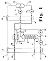
- FIG. 1 is a schematic representation of one embodiment of the cryogenic helium production system of this invention.
- Figure 2 is schematic representation of another embodiment of the invention wherein a reboiler is used in conjunction with a cryogenic rectification column.
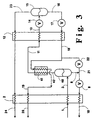
- FIG. 3 is a schematic representation of another embodiment of the invention wherein a separation system employing a dephlegmator is used rather than a column.
- the invention is a cryogenic helium production system which operates at two temperatures regions, an upstream higher temperature region and a downstream lower temperature region.
- the higher temperature region enables the removal of most of the carbon dioxide in the feed by cryogenic rectification or dephlegmation thus eliminating the need for a separate non-cryogenic carbon dioxide removal step.
- the final separation is carried out at the downstream lower temperature region to effectively produce crude helium.
- the dual temperature region system also enables the recovery of a higher pressure hydrocarbon stream from the cryogenic rectification.
- feed 1 generally at a pressure within the range of from 13.8 to 68.9 bar (200 to 1000 pounds per square inch absolute (psia)), is cooled by passage through higher temperature heat exchanger 2 by indirect heat exchange with one or more return streams as will be described more fully later.
- Feed 1 contains helium, carbon dioxide and hydrocarbon.
- the hydrocarbon will include methane and may include one or more heavier hydrocarbons such as the ethane and propane.
- the feed will also generally contain nitrogen.
- Helium is present in the feed generally at a concentration within the range of from 0.1 to 5.0 mole percent.
- Carbon dioxide is present in the feed generally at a concentration up to 1.0 mole percent.
- the balance of the feed comprises hydrocarbon and nitrogen.
- cryogenic rectification column 4 is a stripping column wherein heavier components in upflowing vapor are stripped out by descending liquid.
- the descending liquid is generated by at least partially condensing a vapor stream 5 from the upper portion of column 4 by passage through condenser 6 and returning resulting fluid 7 back into column 4.
- Condenser 6 may be physically outside column 4, as illustrated in the Figure, or it may be within the upper portion of column 4.
- First residue fluid comprises primarily hydrocarbon and nitrogen, if nitrogen is present in the feed, and also contains most of the carbon dioxide which was present in the feed.
- First residue fluid is removed from the lower portion of column 4 as stream 8, passed through valve 9 and warmed within higher temperature heat exchanger 2 wherein it serves to provide refrigeration to cool the feed.
- the resulting warmed first residue fluid may be recovered as stream 10 at an elevated pressure thus reducing hydrocarbon stream compression requirements if compression is desired.
- Helium-enriched fluid generally having a helium concentration within the range of from 0.3 to 15.0 mole percent, is withdrawn from the upper portion of column 4 as stream 11 and passed through lower temperature heat exchanger 12 wherein it is partially condensed at a temperature generally not more than -45.5°C (-50°F). Because most of the carbon dioxide in the feed was removed by the upstream higher temperature processing, the small amount of carbon dioxide remaining in the helium-enriched fluid remains soluble during the downstream lower temperature processing. The carbon dioxide concentration in the helium-enriched fluid will be low enough to prevent freezing of the carbon dioxide in the cold end of the process. Although the carbon dioxide concentration is dependent on the particular process conditions, it will generally be less than 10 parts per million (ppm).
- the two phase stream 13 exiting lower temperature heat exchanger 12 is reduced in pressure through valve 14 and then passed into phase separator 15 wherein it is separated into crude helium vapor and a second residue fluid.
- Second residue fluid comprises primarily hydrocarbon and nitrogen and also contains essentially all of the remaining carbon dioxide, if any, that was not removed with the first residue fluid. Second residue fluid is removed from the lower half or liquid side of phase separator 15 as liquid steam 16, passed through valve 17 and warmed by indirect heat exchange with the partially condensing helium-enriched fluid in lower temperature heat exchanger 12.
- Warmed second residue fluid 18 is then passed through condenser 6 wherein it is further warmed by indirect heat exchange with vapor 5 to partially condense the vapor and provide liquid in line 7 to drive column 4.
- Resulting further warmed second residue fluid 19 is preferably passed through higher temperature heat exchanger 2 to assist in the cooling of the feed and the resulting second residue fluid 20 may be recovered as a lower pressure hydrocarbon stream.
- first residue fluid 8 may be passed through valve 22 and combined with stream 18 to assist in the condensation of vapor in condenser 6 to drive column 4.
- Crude helium vapor is withdrawn from the upper half or vapor side of phase separator 15 as stream 23 and recovered as product crude helium.
- crude helium vapor stream 23 is warmed by passage through lower temperature heat exchanger 12 and higher temperature heat exchanger 2 to assist respectively in the partial condensation of helium-enriched fluid and the cooling of the feed.
- the resulting crude helium vapor is recovered as stream 24.
- the recovery of helium in the crude vapor product will generally be at least 95 percent of the helium in the feed.
- Table 1 For illustrative purposes a computer simulation of the invention was carried out with the embodiment of the invention illustrated in Figure 1. Results of this computer simulation are listed in Table 1. The stream numbers in Table 1 correspond to those of Figure 1. Table 1 1 24 10 20 Flow Rate (kg mol/hr) 453.6 6.35 290.3 157.0 (lbmol/hr) (1000) (14) (640) (346) Temperature (°C) 48.9 47.2 47.2 47.2 (°F) (120) (117) (117) (117) Pressure (bar) 18.2 9.9 13.7 5.2 (psia) (264) (144) (198) (76) Composition, mole% Helium 1.00 70.00 201ppm 0.11 Carbon Dioxide 0.17 -- 0.27 5ppm Nitrogen 32.36 29.20 16.60 61.59 Methane 64.17 0.80 79.52 38.30 Ethane 0.84 -- 1.31 -- Propane 1.01 -- 1.58 -- i-Butane 0.12 -- 0.19 -- n-Butane 0.25 -- 0.
- Figure 2 illustrates another embodiment of the invention wherein a reboiler is added to the column and a small amount of warm feed gas is used to provide reboil for the column.
- the reboiler helps drive helium and nitrogen from the liquid phase, increases the helium recovery and improves the quality of the residue fluid.
- the reboiler may be outside the column as illustated in Figure 2 or it may be within the column.
- the numerals in Figure 2 correspond to those of Figure 1 for the common elements, and these common elements will not be described again in detail.
- liquid 30 from the lower portion of column 4 is passed through reboiler 31 wherein it is vaporized and passed back into column 4 as stream 32 to provide upflowing vapor to the column.
- a portion 33 of warm feed 1 is passed through valve 34 and through reboiler 32 wherein it serves to vaporize liquid 30 by indirect heat exchange.
- the resulting cooled fluid 35 is then passed into column 4 such as by combining with stream 3
- Figure 3 illustrates another embodiment of the invention wherein a separation system comprising a dephlegmator and a separation vessel is used rather than the column and top condenser combination used with the embodiments illustrated in Figures 1 and 2. This arrangement may be preferred if there is little liquid available for use in the column.
- the numerals in Figure 3 correspond to those in Figure 1 for the common elements and these common elements will not be described again in detail.
- feed 3 is passed into separation vessel 40 of a separation system which also comprises dephlegmator 41. Vapor from the upper half of separation vessel 40 passes in line 42 into dephlegmator 41 wherein it is partially condensed by indirect heat exchange with second residue fluid 18 and, if desired, first residue fluid 21 taken from the lower half of separation vessel 40.
- dephlegmator 41 The condensed portion of the vapor passed into dephlegmator 41 is passed back into phase separator or separation vessel 40 through line 42 wherein it forms first residue fluid which is passed out of separation vessel 40 as stream 8 for further processing as previously described.
- Helium-enriched vapor is passed out of dephlegmator 41 as stream 11 and passed to low temperature heat exchanger 12 for further processing as previously described.
- first residue fluid withdrawn from the cryogenic rectification column may be expanded through a liquid turbine enabling a higher pressure residue to be produced and/or allowing a larger fraction of the residue to be produced at a first residue pressure rather than a second residue pressure.
- liquid from phase separator 15 may be flashed to a lower pressure, phase separated in another phase separator, and the resulting vapor combined with the vapor stream withdrawn from phase separator 15 to increase helium recovery.
- the first residue fluid that is throttled may be expanded in a turboexpander, which may be generator loaded or compressor loaded with the power being used to generate electricity or compress one of the product streams or the feed stream.
Landscapes
- Engineering & Computer Science (AREA)
- Physics & Mathematics (AREA)
- Mechanical Engineering (AREA)
- Thermal Sciences (AREA)
- General Engineering & Computer Science (AREA)
- Chemical & Material Sciences (AREA)
- Chemical Kinetics & Catalysis (AREA)
- General Chemical & Material Sciences (AREA)
- Oil, Petroleum & Natural Gas (AREA)
- Separation By Low-Temperature Treatments (AREA)
- Organic Low-Molecular-Weight Compounds And Preparation Thereof (AREA)
- Carbon And Carbon Compounds (AREA)
Claims (10)
- Procédé de rectification cryogénique pour la production d'hélium brut, comprenant les étapes consistant :(A) à refroidir une charge d'alimentation (1) comprenant de l'hélium, un hydrocarbure et du dioxyde de carbone ;(B) à faire passer la charge d'alimentation refroidie (3) dans une colonne (4) et à fractionner la charge d'alimentation présente à l'intérieur de la colonne par rectification cryogénique en un fluide enrichi en hélium (11) et un premier fluide résiduel (8) ;(C) à chauffer le premier fluide résiduel (8) par échange indirect de chaleur avec la charge d'alimentation pour refroidir cette charge d'alimentation ;(D) à condenser partiellement le fluide enrichi en hélium (11) évacué de la colonne pour produire de la vapeur d'hélium brut (23) et un second fluide résiduel (16) ; et(E) à recueillir la vapeur d'hélium brut (24) comme produit consistant en hélium brut ;caractérisé en ce que(F) dans l'étape (A), la charge d'alimentation (3) comprend de l'hélium à une concentration de 0,1 à 5,0 moles %, du dioxyde de carbone à une concentration allant jusqu'à 1,0 mole % et un hydrocarbure à une température comprise dans l'intervalle de -156,7°C à 45,6°C à (-250°F à -50°F) qui est suffisante pour refroidir mais non pour congeler le dioxyde de carbone présent dans la charge d'alimentation ;(G) après l'étape (D), le second fluide résiduel (16) et la vapeur d'hélium brut (23) sont chauffés directement par échange indirect de chaleur avec le fluide enrichi en hélium (11) qui est condensé partiellement à un point en amont du point où le second fluide résiduel (16) est produit ;(H) la vapeur (5) provenant de la colonne (4) est condensée par échange indirect de chaleur avec le second fluide résiduel (16) et le liquide résultant (7) est amené à la colonne ; et(I) le second fluide résiduel est recueilli sous forme d'un courant d'hydrocarbure sous basse pression (20).
- Procédé suivant la revendication 1, comprenant en outre l'étape consistant à faire passer une certaine quantité de fluide résiduel (21) en échange indirect de chaleur avec la vapeur soumise à la condensation de l'étape (H).
- Procédé suivant la revendication 1, comprenant en outre l'étape consistant à faire passer la vapeur d'hélium brut (23) en échange indirect de chaleur avec la charge d'alimentation (1).
- Procédé suivant la revendication 1, comprenant en outre l'étape consistant à faire passer le second fluide résiduel (19) en échange indirect de chaleur avec la charge d'alimentation (1).
- Procédé suivant la revendication 1, comprenant en outre la vaporisation du liquide (30) provenant de la portion inférieure de la colonne de rectification cryogénique (4) par échange indirect de chaleur avec une portion (33) de la charge d'alimentation (1) et à faire passer les deux fluides (32, 35) résultant de cet échange indirect de chaleur dans la colonne de rectification cryogénique.
- Appareil pour la production d'hélium brut, comprenant :(A) un échangeur de chaleur à plus haute température (2), une colonne de rectification cryogénique (4) et un moyen pour faire passer la charge d'alimentation de l'échangeur de chaleur à plus haute température à l'intérieur de la colonne de rectification cryogénique ;(B) un échangeur de chaleur à plus basse température (12) et un moyen pour faire passer le fluide provenant de la portion supérieure de la colonne de rectification cryogénique à l'échangeur de chaleur à plus basse température ;(C) un moyen pour faire passer le fluide (8) de la portion inférieure de la colonne de rectification cryogénique à l'échangeur de chaleur à plus haute température (2) ;(D) un séparateur de phases (15) et un moyen pour faire passer ledit fluide provenant de la portion supérieure de la colonne de rectification cryogénique de l'échangeur de chaleur à plus basse température (12) au séparateur de phases ; et(E) un moyen pour recueillir le fluide évacué du côté de la vapeur du séparateur de phases (15) ;caractérisé par(F) la colonne de rectification cryogénique (4) comportant un condenseur (6) ;(G) un moyen pour faire passer le fluide du côté du liquide du séparateur de phases (15) à l'échangeur de chaleur à plus basse température (12) ;(H) un moyen pour faire passer le fluide de l'échangeur de chaleur à plus basse température (12) au condenseur (6) ;(I) un moyen pour faire passer le fluide du côté de vapeur du séparateur de phase (15) à l'échangeur de chaleur à plus basse température (12) ; et(J) un moyen pour recueillir le fluide évacué du côté du liquide du séparateur de phases (15).
- Appareil suivant la revendication 6, comprenant en outre un moyen pour faire passer le fluide de la portion inférieure de la colonne au condenseur.
- Appareil suivant la revendication 6, comprenant en outre un moyen pour faire passer le fluide du condenseur (6) à l'échangeur de chaleur à plus haute température (2).
- Appareil suivant la revendication 6, dans lequel le moyen pour recueillir le fluide évacué du côté de vapeur du séparateur de phases (15) comprend un moyen pour faire passer le fluide de l'échangeur de chaleur à plus basse température à l'échangeur de chaleur à plus haute température.
- Appareil suivant la revendication 6, comprenant en outre un rebouilleur (31) pour la colonne (4) et un moyen pour faire passer la charge d'alimentation au rebouilleur et du rebouilleur à la colonne.
Applications Claiming Priority (2)
| Application Number | Priority Date | Filing Date | Title |
|---|---|---|---|
| US985982 | 1992-12-04 | ||
| US07/985,982 US5329775A (en) | 1992-12-04 | 1992-12-04 | Cryogenic helium production system |
Publications (2)
| Publication Number | Publication Date |
|---|---|
| EP0600513A1 EP0600513A1 (fr) | 1994-06-08 |
| EP0600513B1 true EP0600513B1 (fr) | 1997-07-16 |
Family
ID=25531968
Family Applications (1)
| Application Number | Title | Priority Date | Filing Date |
|---|---|---|---|
| EP93119548A Expired - Lifetime EP0600513B1 (fr) | 1992-12-04 | 1993-12-03 | Procédé de production d'hélium par voie cryogénique |
Country Status (11)
| Country | Link |
|---|---|
| US (1) | US5329775A (fr) |
| EP (1) | EP0600513B1 (fr) |
| CN (1) | CN1056686C (fr) |
| BR (1) | BR9304930A (fr) |
| CA (1) | CA2110664C (fr) |
| DE (1) | DE69312231T2 (fr) |
| ES (1) | ES2104025T3 (fr) |
| MX (1) | MX9307664A (fr) |
| NO (1) | NO934410L (fr) |
| PL (1) | PL172492B1 (fr) |
| ZA (1) | ZA939086B (fr) |
Families Citing this family (19)
| Publication number | Priority date | Publication date | Assignee | Title |
|---|---|---|---|---|
| US5771714A (en) * | 1997-08-01 | 1998-06-30 | Praxair Technology, Inc. | Cryogenic rectification system for producing higher purity helium |
| DE10007440A1 (de) * | 2000-02-18 | 2001-08-23 | Linde Ag | Verfahren zum Abtrennen einer Helium-reichen Fraktion aus einem wenigstens Methan, Stickstoff und Helium enthaltenden Strom |
| US6349566B1 (en) | 2000-09-15 | 2002-02-26 | Air Products And Chemicals, Inc. | Dephlegmator system and process |
| FR2832213B1 (fr) * | 2001-11-12 | 2004-09-24 | Air Liquide | Procede et installation de production d'helium |
| US20040194513A1 (en) * | 2003-04-04 | 2004-10-07 | Giacobbe Frederick W | Fiber coolant system including improved gas seals |
| US20050217479A1 (en) * | 2004-04-02 | 2005-10-06 | Membrane Technology And Research, Inc. | Helium recovery from gas streams |
| US7454923B2 (en) * | 2004-11-12 | 2008-11-25 | Praxair Technology, Inc. | Light component separation from a carbon dioxide mixture |
| US7201019B2 (en) * | 2004-11-19 | 2007-04-10 | Praxair Technology, Inc. | Light gas component separation from a carbon dioxide mixture |
| DE102005010053A1 (de) * | 2005-03-04 | 2006-09-07 | Linde Ag | Helium-Gewinnung bei LNG-Anlagen |
| FR2936864B1 (fr) * | 2008-10-07 | 2010-11-26 | Technip France | Procede de production de courants d'azote liquide et gazeux, d'un courant gazeux riche en helium et d'un courant d'hydrocarbures deazote et installation associee. |
| EP2350546A1 (fr) * | 2008-10-07 | 2011-08-03 | Exxonmobil Upstream Research Company | Récupération de l hélium dans le gaz naturel intégrée à la récupération du lgn |
| US8152898B2 (en) * | 2008-10-24 | 2012-04-10 | Praxair Technology, Inc. | Helium recovery process |
| US10036590B2 (en) | 2012-08-02 | 2018-07-31 | Air Products And Chemicals, Inc. | Helium recovery from streams containing helium, carbon dioxide, and at least one of nitrogen and methane |
| US9791210B2 (en) * | 2012-08-02 | 2017-10-17 | Air Products And Chemicals, Inc. | Systems and methods for recovering helium from feed streams containing carbon dioxide |
| US20160265842A1 (en) * | 2015-03-12 | 2016-09-15 | Michael J. Dray | Light gas separation process and system |
| CN109294647B (zh) * | 2018-09-17 | 2021-08-13 | 广州智光节能有限公司 | 天然气的提纯系统 |
| US11353261B2 (en) | 2019-10-31 | 2022-06-07 | Air Products And Chemicals, Inc. | Lights removal from carbon dioxide |
| CN111981767B (zh) * | 2020-08-20 | 2024-03-08 | 中国石油工程建设有限公司 | 一种天然气单塔深冷提氦装置和方法 |
| EP4144431A1 (fr) * | 2021-09-06 | 2023-03-08 | Linde GmbH | Procédé et installation de traitement technique de séparation d'un mélange gazeux |
Family Cites Families (15)
| Publication number | Priority date | Publication date | Assignee | Title |
|---|---|---|---|---|
| US3355902A (en) * | 1964-05-11 | 1967-12-05 | Pullman Inc | Helium recovery process |
| US3815376A (en) * | 1969-07-31 | 1974-06-11 | Airco Inc | Process and system for the production and purification of helium |
| GB1351598A (en) * | 1970-03-26 | 1974-05-01 | Air Prod & Chem | Separation of gas mixtures |
| DE2022954C3 (de) * | 1970-05-12 | 1978-05-18 | Linde Ag, 6200 Wiesbaden | Verfahren zur Zerlegung von stickstoffhaltigem Erdgas |
| US3740962A (en) * | 1970-09-18 | 1973-06-26 | Commw Ass Inc | Process of and apparatus for the recovery of helium from a natural gas stream |
| US3992167A (en) * | 1975-04-02 | 1976-11-16 | Union Carbide Corporation | Low temperature refrigeration process for helium or hydrogen mixtures using mixed refrigerant |
| DE2849344C2 (de) * | 1978-11-14 | 1987-01-29 | Linde Ag, 6200 Wiesbaden | Verfahren zur Abtrennung einer C↓2↓↓+↓-Kohlenwasserstoff-Fraktion aus Erdgas |
| US4664686A (en) * | 1986-02-07 | 1987-05-12 | Union Carbide Corporation | Process to separate nitrogen and methane |
| US4701201A (en) * | 1986-09-24 | 1987-10-20 | Union Carbide Corporation | Process to produce cold helium gas for liquefaction |
| US4701200A (en) * | 1986-09-24 | 1987-10-20 | Union Carbide Corporation | Process to produce helium gas |
| US4758258A (en) * | 1987-05-06 | 1988-07-19 | Kerr-Mcgee Corporation | Process for recovering helium from a natural gas stream |
| DE3802553C2 (de) * | 1988-01-28 | 1996-06-20 | Linde Ag | Verfahren zur Abtrennung von Kohlenwasserstoffen |
| US4805413A (en) * | 1988-03-10 | 1989-02-21 | Kerr-Mcgee Corporation | Process for cryogenically separating natural gas streams |
| US5011521A (en) * | 1990-01-25 | 1991-04-30 | Air Products And Chemicals, Inc. | Low pressure stripping process for production of crude helium |
| US5017204A (en) * | 1990-01-25 | 1991-05-21 | Air Products And Chemicals, Inc. | Dephlegmator process for the recovery of helium |
-
1992
- 1992-12-04 US US07/985,982 patent/US5329775A/en not_active Expired - Fee Related
-
1993
- 1993-12-03 BR BR9304930A patent/BR9304930A/pt not_active IP Right Cessation
- 1993-12-03 NO NO934410A patent/NO934410L/no not_active Application Discontinuation
- 1993-12-03 ZA ZA939086A patent/ZA939086B/xx unknown
- 1993-12-03 ES ES93119548T patent/ES2104025T3/es not_active Expired - Lifetime
- 1993-12-03 DE DE69312231T patent/DE69312231T2/de not_active Expired - Fee Related
- 1993-12-03 CN CN93120814A patent/CN1056686C/zh not_active Expired - Fee Related
- 1993-12-03 CA CA002110664A patent/CA2110664C/fr not_active Expired - Fee Related
- 1993-12-03 PL PL93301311A patent/PL172492B1/pl unknown
- 1993-12-03 MX MX9307664A patent/MX9307664A/es not_active IP Right Cessation
- 1993-12-03 EP EP93119548A patent/EP0600513B1/fr not_active Expired - Lifetime
Also Published As
| Publication number | Publication date |
|---|---|
| ZA939086B (en) | 1994-08-05 |
| PL172492B1 (pl) | 1997-09-30 |
| CA2110664C (fr) | 1996-12-24 |
| NO934410D0 (no) | 1993-12-03 |
| BR9304930A (pt) | 1994-08-09 |
| NO934410L (no) | 1994-06-06 |
| US5329775A (en) | 1994-07-19 |
| EP0600513A1 (fr) | 1994-06-08 |
| MX9307664A (es) | 1994-06-30 |
| DE69312231T2 (de) | 1998-02-19 |
| CN1091515A (zh) | 1994-08-31 |
| CA2110664A1 (fr) | 1994-06-05 |
| DE69312231D1 (de) | 1997-08-21 |
| ES2104025T3 (es) | 1997-10-01 |
| PL301311A1 (en) | 1994-06-13 |
| CN1056686C (zh) | 2000-09-20 |
Similar Documents
| Publication | Publication Date | Title |
|---|---|---|
| EP0600513B1 (fr) | Procédé de production d'hélium par voie cryogénique | |
| EP0173168B1 (fr) | Procédé pour la production d'oxygène de très haute pureté | |
| CA2145445C (fr) | Systeme de rectification cryogenique pour l'obtention d'azote sous haute pression | |
| EP0231949B2 (fr) | Procédé de séparation de l'ozote du méthane | |
| EP0464630B2 (fr) | Système de séparation cryogénique de l'air à vaporiseur auxiliaire pour les deux produits | |
| US5228296A (en) | Cryogenic rectification system with argon heat pump | |
| EP0464635B1 (fr) | Séparation cryogénique de l'air à double condenseur auxiliaire (annexe) pour l'amenée d'air | |
| US5235816A (en) | Cryogenic rectification system for producing high purity oxygen | |
| EP0464636B2 (fr) | Séparation cryogénique d'air avec double expansion à turbo des amenées d'air à température différente | |
| US5114452A (en) | Cryogenic air separation system for producing elevated pressure product gas | |
| US6279345B1 (en) | Cryogenic air separation system with split kettle recycle | |
| US5230217A (en) | Inter-column heat integration for multi-column distillation system | |
| EP0169679B1 (fr) | Procédé de séparation d'air | |
| EP0563800B1 (fr) | Procédé de rectification cryogénique à récupération élevée | |
| US5771714A (en) | Cryogenic rectification system for producing higher purity helium | |
| EP0222026B1 (fr) | Procédé de préparation d'un concentré crypton-xénon exempt d'oxygène | |
| EP0567098B1 (fr) | Système de rectification cryogénique à double pompe à chaleur | |
| US5144808A (en) | Cryogenic air separation process and apparatus | |
| EP0418139A1 (fr) | Procédé et dispositif pour la séparation cryogénique d'air | |
| US4805413A (en) | Process for cryogenically separating natural gas streams | |
| US4701201A (en) | Process to produce cold helium gas for liquefaction | |
| US5386691A (en) | Cryogenic air separation system with kettle vapor bypass | |
| JPS61289284A (ja) | 空気分離方法並びに装置 |
Legal Events
| Date | Code | Title | Description |
|---|---|---|---|
| PUAI | Public reference made under article 153(3) epc to a published international application that has entered the european phase |
Free format text: ORIGINAL CODE: 0009012 |
|
| AK | Designated contracting states |
Kind code of ref document: A1 Designated state(s): DE ES GB IT NL |
|
| 17P | Request for examination filed |
Effective date: 19940615 |
|
| 17Q | First examination report despatched |
Effective date: 19950906 |
|
| GRAG | Despatch of communication of intention to grant |
Free format text: ORIGINAL CODE: EPIDOS AGRA |
|
| RTI1 | Title (correction) | ||
| GRAH | Despatch of communication of intention to grant a patent |
Free format text: ORIGINAL CODE: EPIDOS IGRA |
|
| GRAG | Despatch of communication of intention to grant |
Free format text: ORIGINAL CODE: EPIDOS AGRA |
|
| GRAH | Despatch of communication of intention to grant a patent |
Free format text: ORIGINAL CODE: EPIDOS IGRA |
|
| GRAA | (expected) grant |
Free format text: ORIGINAL CODE: 0009210 |
|
| ITF | It: translation for a ep patent filed | ||
| AK | Designated contracting states |
Kind code of ref document: B1 Designated state(s): DE ES GB IT NL |
|
| REF | Corresponds to: |
Ref document number: 69312231 Country of ref document: DE Date of ref document: 19970821 |
|
| REG | Reference to a national code |
Ref country code: ES Ref legal event code: FG2A Ref document number: 2104025 Country of ref document: ES Kind code of ref document: T3 |
|
| PLBE | No opposition filed within time limit |
Free format text: ORIGINAL CODE: 0009261 |
|
| STAA | Information on the status of an ep patent application or granted ep patent |
Free format text: STATUS: NO OPPOSITION FILED WITHIN TIME LIMIT |
|
| 26N | No opposition filed | ||
| REG | Reference to a national code |
Ref country code: GB Ref legal event code: IF02 |
|
| PGFP | Annual fee paid to national office [announced via postgrant information from national office to epo] |
Ref country code: NL Payment date: 20021121 Year of fee payment: 10 |
|
| PGFP | Annual fee paid to national office [announced via postgrant information from national office to epo] |
Ref country code: ES Payment date: 20030109 Year of fee payment: 10 |
|
| PGFP | Annual fee paid to national office [announced via postgrant information from national office to epo] |
Ref country code: GB Payment date: 20031126 Year of fee payment: 11 |
|
| PG25 | Lapsed in a contracting state [announced via postgrant information from national office to epo] |
Ref country code: ES Free format text: LAPSE BECAUSE OF NON-PAYMENT OF DUE FEES Effective date: 20031204 |
|
| PGFP | Annual fee paid to national office [announced via postgrant information from national office to epo] |
Ref country code: DE Payment date: 20040202 Year of fee payment: 11 |
|
| PG25 | Lapsed in a contracting state [announced via postgrant information from national office to epo] |
Ref country code: NL Free format text: LAPSE BECAUSE OF NON-PAYMENT OF DUE FEES Effective date: 20040701 |
|
| NLV4 | Nl: lapsed or anulled due to non-payment of the annual fee |
Effective date: 20040701 |
|
| PG25 | Lapsed in a contracting state [announced via postgrant information from national office to epo] |
Ref country code: GB Free format text: LAPSE BECAUSE OF NON-PAYMENT OF DUE FEES Effective date: 20041203 |
|
| REG | Reference to a national code |
Ref country code: ES Ref legal event code: FD2A Effective date: 20031204 |
|
| PG25 | Lapsed in a contracting state [announced via postgrant information from national office to epo] |
Ref country code: DE Free format text: LAPSE BECAUSE OF NON-PAYMENT OF DUE FEES Effective date: 20050701 |
|
| GBPC | Gb: european patent ceased through non-payment of renewal fee |
Effective date: 20041203 |
|
| PG25 | Lapsed in a contracting state [announced via postgrant information from national office to epo] |
Ref country code: IT Free format text: LAPSE BECAUSE OF NON-PAYMENT OF DUE FEES;WARNING: LAPSES OF ITALIAN PATENTS WITH EFFECTIVE DATE BEFORE 2007 MAY HAVE OCCURRED AT ANY TIME BEFORE 2007. THE CORRECT EFFECTIVE DATE MAY BE DIFFERENT FROM THE ONE RECORDED. Effective date: 20051203 |