EP0600550A1 - Automatische und pneumatische Entleervorrichtung für Röhre von flüssigem Mist Verteiler - Google Patents
Automatische und pneumatische Entleervorrichtung für Röhre von flüssigem Mist Verteiler Download PDFInfo
- Publication number
- EP0600550A1 EP0600550A1 EP93203313A EP93203313A EP0600550A1 EP 0600550 A1 EP0600550 A1 EP 0600550A1 EP 93203313 A EP93203313 A EP 93203313A EP 93203313 A EP93203313 A EP 93203313A EP 0600550 A1 EP0600550 A1 EP 0600550A1
- Authority
- EP
- European Patent Office
- Prior art keywords
- valve
- oil
- drawer
- hydraulic
- machine
- Prior art date
- Legal status (The legal status is an assumption and is not a legal conclusion. Google has not performed a legal analysis and makes no representation as to the accuracy of the status listed.)
- Withdrawn
Links
Images

Classifications
-
- A—HUMAN NECESSITIES
- A01—AGRICULTURE; FORESTRY; ANIMAL HUSBANDRY; HUNTING; TRAPPING; FISHING
- A01C—PLANTING; SOWING; FERTILISING
- A01C23/00—Distributing devices specially adapted for liquid manure or other fertilising liquid, including ammonia, e.g. transport tanks or sprinkling wagons
- A01C23/02—Special arrangements for delivering the liquid directly into the soil
- A01C23/021—Sludge injectors, i.e. liquid manure injectors
- A01C23/022—Continuous injection tools
-
- A—HUMAN NECESSITIES
- A01—AGRICULTURE; FORESTRY; ANIMAL HUSBANDRY; HUNTING; TRAPPING; FISHING
- A01C—PLANTING; SOWING; FERTILISING
- A01C23/00—Distributing devices specially adapted for liquid manure or other fertilising liquid, including ammonia, e.g. transport tanks or sprinkling wagons
- A01C23/001—Sludge spreaders, e.g. liquid manure spreaders
- A01C23/002—Sludge spreaders, e.g. liquid manure spreaders provided with auxiliary arrangements, e.g. pumps, agitators, cutters
Definitions
- the present invention relates to machines intended for spreading or injecting slurry or other fertilizing materials and provided with a cleaning device by ventilation generated by the vacuum pump of the supply tank.
- the invention relates in particular to a system automatically ensuring the pneumatic purging of the lines of the machine after the stopping of the spreading or of the injection and before the lifting of the machine.
- the object of the invention is threefold: it is to eliminate untimely slurry flows on the edges of treated plots or on the road by cleaning the machine by ventilation before lifting it, while minimizing the loss of internal compression of the supply tank and avoiding as much as possible the rejection of stale air into the atmosphere.
- the market already offers one or the other pneumatic system using compressed air in the tank and operating alternately with the slurry valve or machine lift control.
- the automatic pipe purging system consists of a pipe ventilation circuit generated by the expulsion process pneumatic tank.
- This ventilation circuit is characterized in that it is regulated by an apparatus of valves with temporary opening, the control of which is integrated within a sequential hydraulic distribution system actuating and cutting off said circuit at a determined time between the closing of the fertilizer supply valve and the lifting of the machine.
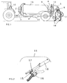
- FIG. 1 shows the assembly diagram according to the invention, illustrated for better clarity, in the case of a slurry injection machine in culture.
- the system is supplied with air by the same vacuum pump 1, which is used to compress the slurry in the tank 13.
- the air is captured in 2 at any point in the compression circuit between the pump 1 and the tank 13 or on one of these two elements; a pipe 3 brings the compressed air to a temporary opening valve system 11 and directs it upstream of the injection system to a non-return valve 12 fixed to the supply pipe 5 of the distributor 6.
- This is the distributor itself which ensures the ventilation of the air through the various injection pipes 7, expelling the residual slurry into the ground via the injection nozzles 8.
- the system is put into service automatically by a hydraulic distribution block sequential 9, when the driver actuates the tractor distributor 10 to stop injection and lift the tool 14.
- FIG 2 gives the detailed composition of the temporary opening valve system shown schematically in Figure 1 at item 11.
- This system in the specific case present, consists of a pinion 15, a valve 16, a rack 17 and an actuator 18.
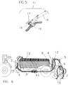
- the vacuum pump 1 generates the pressure (shown in dark hatching) in the tank 13 to expel the slurry (shown in light hatched) to the injectors 8 which bury it in the ground. Pump 1 also generates pressure in the first part 3 of the purge system.
- FIG. 5 shows how the jack 18 opens the ventilation valve 16 which releases compressed air to its mother line 5, then the distributor 6, which distributes it regularly to the various injection pipes 7.
- the pinion 15 is fixed in one direction, free in the other, thanks to a system of pawls.
- the sequential hydraulic distribution block 9 controls the retraction of the jack 18, so as to adjust the ventilation time and the rotation time of the distributor 6.
- the length of the jack 18 is determined to open and then close valve 16 in one stroke: when the cylinder is fully retracted, valve 16 is therefore closed again.
- the stroke time of the jack 18 and therefore the duration of ventilation are preset from sequential hydraulic control 9.
- the air path through the machine is shown in FIG. 6.
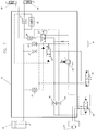
- FIG. 7 shows the sequential hydraulic distribution block 9 in the form of a hydraulic diagram within which the pilotings are shown in broken lines.
- the block is controlled by the distributor 10 of the tractor represented here by its hydraulic slide 19.
- the operator actuates the distributor 10, which thus moves the drawer to the left: the oil is thus compressed towards the sequential block 9.
- the compressed oil goes to the piloted non-return valves 21 and 24, which she piloted in the open position. Since the valve 21 is open, the oil which held the single-acting cylinder 22 for lifting the tool in the retracted position can escape, thus leaving the cylinder 22: and the tool descends.
- the oil escaping from the jack 22 passes through the valve 21 again to pilot the hydraulic slide 23 to the right. Once this drawer in the piloted position, the oil escaping from the jack 22 is blocked there; it then escapes, via the valve 24 piloted in the open position, towards the oil reservoir 25 of the tractor.
- the oil must go to the hydraulic slide 33, which it controls in the closed position to block the machine lifting circuit. At this time, the oil pressure increases within the block, since the oil is blocked at the jacks 28 and 29 and at the drawer 33.
- the pressure relief valve 32 opens, thus allowing the oil in the operating circuit of the distributor motor 31 to move. In fact, the pressure of the valve 32 is tared at a higher level than that of the opening of the jacks 28 and 29.
- the oil first spins it towards the drawer 33, where it is blocked, since this drawer is controlled in the closed position. Consequently, the oil goes to the valve 26, which it controls in the open position, as well as to the non-return valve 35 which it crosses to continue, not to the non-return valve 30 where it is blocked, but towards the operating circuit of the distributor motor 31, via the slide 20, then towards the pressure relief valve 32 and finally the oil tank 25 of the tractor.
- the engine of the distributor is thus started again.
Landscapes
- Life Sciences & Earth Sciences (AREA)
- Soil Sciences (AREA)
- Engineering & Computer Science (AREA)
- Water Supply & Treatment (AREA)
- Environmental Sciences (AREA)
- Fluid-Pressure Circuits (AREA)
Applications Claiming Priority (2)
| Application Number | Priority Date | Filing Date | Title |
|---|---|---|---|
| BE9201039 | 1992-11-27 | ||
| BE9201039A BE1006380A3 (fr) | 1992-11-27 | 1992-11-27 | Purgeur pneumatique automatise des conduites de machines d'epandage ou d'injection de lisier ou autres fertilisants. |
Publications (1)
| Publication Number | Publication Date |
|---|---|
| EP0600550A1 true EP0600550A1 (de) | 1994-06-08 |
Family
ID=3886547
Family Applications (1)
| Application Number | Title | Priority Date | Filing Date |
|---|---|---|---|
| EP93203313A Withdrawn EP0600550A1 (de) | 1992-11-27 | 1993-11-26 | Automatische und pneumatische Entleervorrichtung für Röhre von flüssigem Mist Verteiler |
Country Status (2)
| Country | Link |
|---|---|
| EP (1) | EP0600550A1 (de) |
| BE (1) | BE1006380A3 (de) |
Cited By (3)
| Publication number | Priority date | Publication date | Assignee | Title |
|---|---|---|---|---|
| CN107517635A (zh) * | 2017-07-18 | 2017-12-29 | 全椒县汊河农机服务专业合作社 | 一种穿戴式农用肥料注料机 |
| CN111226768A (zh) * | 2020-03-28 | 2020-06-05 | 长江大学 | 田间自动施水肥系统 |
| WO2024052813A1 (fr) * | 2022-09-05 | 2024-03-14 | Jua | Dispositif et procédé d'épandage de fertilisants dans un sol agricole |
Citations (2)
| Publication number | Priority date | Publication date | Assignee | Title |
|---|---|---|---|---|
| FR2516348A1 (fr) * | 1981-11-19 | 1983-05-20 | Puissant Philippe | Circuit de distribution d'un liquide pour un appareil de pulverisation a usage agricole avec conduite pour fluide de nettoyage des buses |
| EP0507759A1 (de) * | 1991-03-28 | 1992-10-07 | Ets JOSKIN S.A. | Düngereinbringer mit konstantem Drück |
-
1992
- 1992-11-27 BE BE9201039A patent/BE1006380A3/fr not_active IP Right Cessation
-
1993
- 1993-11-26 EP EP93203313A patent/EP0600550A1/de not_active Withdrawn
Patent Citations (2)
| Publication number | Priority date | Publication date | Assignee | Title |
|---|---|---|---|---|
| FR2516348A1 (fr) * | 1981-11-19 | 1983-05-20 | Puissant Philippe | Circuit de distribution d'un liquide pour un appareil de pulverisation a usage agricole avec conduite pour fluide de nettoyage des buses |
| EP0507759A1 (de) * | 1991-03-28 | 1992-10-07 | Ets JOSKIN S.A. | Düngereinbringer mit konstantem Drück |
Cited By (4)
| Publication number | Priority date | Publication date | Assignee | Title |
|---|---|---|---|---|
| CN107517635A (zh) * | 2017-07-18 | 2017-12-29 | 全椒县汊河农机服务专业合作社 | 一种穿戴式农用肥料注料机 |
| CN111226768A (zh) * | 2020-03-28 | 2020-06-05 | 长江大学 | 田间自动施水肥系统 |
| CN111226768B (zh) * | 2020-03-28 | 2021-06-11 | 长江大学 | 田间自动施水肥系统 |
| WO2024052813A1 (fr) * | 2022-09-05 | 2024-03-14 | Jua | Dispositif et procédé d'épandage de fertilisants dans un sol agricole |
Also Published As
| Publication number | Publication date |
|---|---|
| BE1006380A3 (fr) | 1994-08-09 |
Similar Documents
| Publication | Publication Date | Title |
|---|---|---|
| EP2611289B1 (de) | Sprühanordnung und zerstäuber mit mindestens einer derartigen anordnung | |
| FR2464392A1 (fr) | Circuit hydraulique pour la commande de verins hydrauliques a double effet | |
| EP2608662B1 (de) | System und verfahren zum befüllen eines spraybehälters | |
| EP0494031B1 (de) | Flüssigkeitsverteilungvorrichtung für ein Apparat zum Reinigen, Desinfizieren und Schmieren zahnärtzlicher Handstücke | |
| FR2760597A1 (fr) | Dispositif de chargement pour des machines agricoles de recolte | |
| BE1006380A3 (fr) | Purgeur pneumatique automatise des conduites de machines d'epandage ou d'injection de lisier ou autres fertilisants. | |
| EP4287816A1 (de) | Landwirtschaftliche versorgungs- und/oder wartungsanlage und/oder zugehöriges versorgungs- und/oder wartungsverfahren | |
| US4091751A (en) | Planting machine | |
| DE2736587B2 (de) | Kanalreinigungsfahrzeug | |
| EP2105368A1 (de) | Hydraulikkreislauf für Waggon, insbesondere einen Schotterwagen | |
| EP0264328B1 (de) | Vorrichtung zum Auswerfen eines Ballens, geformt in einer Rundballenpresse | |
| CN111066618A (zh) | 一种果树移植机 | |
| EP4062752B1 (de) | Modul zur complantation von rebenpflanzen, vorrichtung zur complantation, die dieses modul umfasst | |
| FR2737423A1 (fr) | Circuit hydraulique comprenant une installation automatique de circulation inverse pour une unite de filtration | |
| EP1188375A1 (de) | Landwirtschafliche Feldspritze | |
| EP2858479B1 (de) | Ein flüssigkeitsverteilungssystem und ein verfahren zum verteilen von flüssigkeit auf einem feld | |
| EP1583481A1 (de) | Verfahren und vorrichtung für den umgang mit schwergas | |
| FR2589033A1 (fr) | Perfectionnement au dispositif de controle automatique de position de l'outil interceps | |
| EP4120817A1 (de) | Verfahren zum verteilen von schlamm und zur implementierung davon geeigneter zerstäuber | |
| WO2024201286A1 (fr) | Dispositif d'introduction d'au moins un intrant dans le sol et procédé d'introduction d'au moins un intrant mettant en oeuvre un tel dispositif | |
| EP0408519A1 (de) | Filtereinrichtung für eine Anlage zum kontinuierlichen Absaugen von textilen Abfällen von Maschinen zum Anfertigen von Textilien | |
| EP0507759B1 (de) | Düngereinbringer mit konstantem Drück | |
| EP4007492B1 (de) | Vorrichtung zur thermischen bekämpfung von unkraut | |
| FR2781119A1 (fr) | Installation d'hydro-curage par chasse d'eau pour aire de vie d'animaux en particulier d'elevage | |
| BE1019617A3 (fr) | Godet de desilage. |
Legal Events
| Date | Code | Title | Description |
|---|---|---|---|
| PUAI | Public reference made under article 153(3) epc to a published international application that has entered the european phase |
Free format text: ORIGINAL CODE: 0009012 |
|
| AK | Designated contracting states |
Kind code of ref document: A1 Designated state(s): AT CH DE DK ES FR GB IE IT LI LU NL SE |
|
| 17P | Request for examination filed |
Effective date: 19941130 |
|
| 17Q | First examination report despatched |
Effective date: 19960725 |
|
| 18D | Application deemed to be withdrawn |
Effective date: 19961205 |