EP0600695A2 - Communications sans fil utilisant l'accouplement à courte distance - Google Patents
Communications sans fil utilisant l'accouplement à courte distance Download PDFInfo
- Publication number
- EP0600695A2 EP0600695A2 EP93309505A EP93309505A EP0600695A2 EP 0600695 A2 EP0600695 A2 EP 0600695A2 EP 93309505 A EP93309505 A EP 93309505A EP 93309505 A EP93309505 A EP 93309505A EP 0600695 A2 EP0600695 A2 EP 0600695A2
- Authority
- EP
- European Patent Office
- Prior art keywords
- antenna
- base stations
- signals
- service area
- near field
- Prior art date
- Legal status (The legal status is an assumption and is not a legal conclusion. Google has not performed a legal analysis and makes no representation as to the accuracy of the status listed.)
- Granted
Links
Images


Classifications
-
- H—ELECTRICITY
- H04—ELECTRIC COMMUNICATION TECHNIQUE
- H04B—TRANSMISSION
- H04B5/00—Near-field transmission systems, e.g. inductive or capacitive transmission systems
- H04B5/20—Near-field transmission systems, e.g. inductive or capacitive transmission systems characterised by the transmission technique; characterised by the transmission medium
- H04B5/22—Capacitive coupling
-
- H—ELECTRICITY
- H04—ELECTRIC COMMUNICATION TECHNIQUE
- H04B—TRANSMISSION
- H04B5/00—Near-field transmission systems, e.g. inductive or capacitive transmission systems
- H04B5/40—Near-field transmission systems, e.g. inductive or capacitive transmission systems characterised by components specially adapted for near-field transmission
- H04B5/48—Transceivers
Definitions
- This invention relates to wireless communication systems, and more particularly, to cellular local area networks (LANs) and the like that have radio linked access channels.
- LANs local area networks
- the system bandwidth is much greater than the bandwidth of any individual cell. Indeed, to a first approximation, the aggregate bandwidth of such a system can approach the sum of the bandwidths of the individual cells. This is an important feature of existing cellular systems because it enables them to service far more traffic than any single cell is required to handle, thereby reducing the cost and complexity of the individual cells and of the overall system.
- Client access i.e., user and networked device access
- known cellular systems typically is provided by far field coupled radio links.
- the far field electric and magnetic field strengths of a radiating element, such as an antenna fall-off as the inverse first power of the propagation distance, r (i.e., 1/r), so the power falls-off as 1/r2.
- neighboring cells within these far field coupled cellular systems operate on different carrier frequencies (i.e., different "channels"), thereby ensuring that cells operating on like channels are spatially separated from each other by buffer zones of sufficient size to maintain an adequate signal-to-interference level throughout each of the cells.
- farfield coupled radio links in local communication systems, such as cellular LANs, is that these systems often are installed in environments containing various rf reflectors, such as in buildings having metal wall studs.
- farfield coupled cellular systems generally operate at UHF frequencies to enable modest sized antennae to function as efficient radiators.
- UHF signals have wavelengths on the order of only one foot or so, which means that even relatively small objects can cause significant reflections.
- buildings or similar sites where many of the rf reflectors are spatially separated from the radiating source and from each other by distances that are relatively small multiples of the signal wavelength, such as the reflectors in and near the walls of a small room or office, such rf reflections tend to produce strong resonances.
- the standing wave patterns that are associated with these resonances tend to materially perturb the radiated fields in accordance with a pattern which is complex and difficult to predict (see Fig. 2).
- the problems that are caused by these standing wave patterns would be compounded if adjacent, spatially contiguous cells were operated on the same carrier frequencies because the standing wave patterns that are generated within the adjacent cells then would cause the transitions from cell-to-cell to be non-monotonic.
- the present invention provides a near field coupled communication system for providing two-way communication services within a predetermined service area; said system comprising a plurality of stationary base stations that are spatially distributed within said service area, each of said base stations having an antenna for transmitting output signals and for sensing input signals; and at least one portable station that is transportable from position-to-position within said service area, each portable station having an antenna for transmitting output signals and for sensing input signals; said base stations being positioned to cause the antenna of each portable station that is within said service area to be near field coupled to the antenna of at least one of said base stations whenever signals are being transferred in either direction between said portable station and said base station, with the near field coupling of said antennae being sufficiently strong to predominantly govern the transfer of said signals.
- the present invention further provides a LAN according to claim 4 of the appended claims.
- said service area is composed of a plurality of definition cells; said base stations are spatially distributed within said service area to transfer data modulated carrier signals to and from each portable station while said portable station is located within different ones of said cells.
- the antenna of each of said base stations is a dual loop antenna that is composed of first and second antenna loops that are spatially oriented in quadrature relationship with respect to each other; each of said base stations further includes means for driving its first and second antenna loops in phase quadrature when said base station is operating in a transmit mode, and means for combining the signals sensed by its first and second antenna loops in phase quadrature while said base station is operating in a receive mode; and each portable station is further characterized by the antenna thereof being a loop antenna.
- said service area is located within a building having a plurality of rooms; and at least some of said rooms are within different ones of said cells.
- the antenna of at least one of said base stations may be composed of a single elongated loop that is crisscrossed at regular spatial intervals along its length.
- the present invention further provides a method for wirelessly communicating data according to claim 10 of the appended claims.
- said base stations are positioned to exchange data with said portable station while said portable station is within different sectors of said service area.
- an energized antenna In addition to far field radiation, an energized antenna also produces field components which do not give rise to propagating waves. These non-propagating components are known as the "near field.” and are quite analogous to the concept of reactive power in circuit theory. Near field components, which consist of electric and magnetic fields, are "bound” to the transmitting antenna. They, therefore, transfer real power only when a receiving antenna is sufficiently close to the transmitter (i. e., within its "near field region"). This is in stark contrast to the far field components which radiate energy even in the absence of a receiver. Although all active antennae exhibit near field effects, magnetic dipoles provide a useful and simple means for taking practical advantage of them. It, however, is to be noted that a completely analogous set of properties exists for electric dipoles.
- the magnetic field created by a small oscillating current circulating in a loop is defined by the following relationships: wherein A is the area of the loop, I is the peak current in the loop, r is the distance from the center of the loop, ⁇ is the angle to the loop axis, ⁇ is the azimuthal angle, ⁇ is the characteristic impedance of free space (377 ⁇ ), and k is the propagation constant (k is equal to ⁇ /c, where ⁇ is the angular frequency and c is the speed of light).
- Equations 1 -3 are near field terms that represent trapped energy.
- the important property of this trapped energy is the spatial decay rates of their field components, which are 1/r2 or 1/r3.
- Equations (1) - (3) also demonstrate that the dipole strength, IA, and the angular frequency, ⁇ , determine the radiation field. As the frequency is increased (or wavelength reduced), the region in which the near field dominates is more restricted to the vicinity of the antenna. Thus, in a near field cellular system, the cell size is largely influenced by the carrier frequency. For office-size cells, a carrier frequency of 5-15 MHz generally is appropriate, but it is to be understood that these systems can be designed to operate at carrier frequencies above and below this range to tailor them to different operating environments.
- Equations (1) - (3) demonstrate that the dipole strength, IA, varies directly with loop area, while Equation (5) shows that the inductance varies only as the square root of the loop area times the logarithm of the area. This means that the dipole strength is an increasing function of the loop area when the antenna is driven from a constant voltage source. In other words, a given voltage will produce a stronger field as the area of the loop is increased.
- the dipole strength, IA, beyond the near field region as defined above at a carrier frequency of, for example, 5.3 MHz, preferably is: IA ⁇ 0.0081 where IA has units of (amps m2). From this it will be evident that the area, A, of the loop antenna and the peak current, I, that is applied thereto can be traded off, one against the other, while limiting the far field dipole strength to a desirably low level.
- An especially convenient method for driving a loop antenna is to use a class C driver stage connected directly to the loop.
- a simple resonant circuit having a parallel capacitor and resistor in parallel with the loop allows the loop current to be derived primarily from resonance, rather than from real (D.C.) power (the resistor advantageously is included to provide some bandwidth broadening). If a 5 volt logic level is chosen as the rail voltage for such a driver and if the carrier frequency is selected to be 5.3 MHz, equations (6) and (7) can be used to show that a loop antenna that is formed from wire having a diameter of 0.125 inches can have an area of up to 0.244 m2.
- loop antennae having areas of about 0.12 m2 (20 in2) have been successfully employed for implementing this invention.
- the inductance of such a loop is about 300nH, and the inductive reactance is about 10 ⁇ .
- capacitance is about 3000pF.
- a LAN typically has adequate bandwidth for supporting essentially simultaneous message traffic to and from a substantial number of different clients.
- this message traffic may be carried on the LAN in packets or data blocks, each of which is appropriately addressed to one or more of the clients.
- the bandwidth of the LAN is fairly allocated among the clients that are being serviced by the LAN, so that no single client or subset of clients is permitted to consume more than its fair share of the available bandwidth.
- a contention controlled access mechanism permits a larger fractional portion of the bandwidth of the LAN to be allocated to each of the cells that are active at any instant in time than a demand access mechanism, but that topic is beyond the scope of this invention.
- the cellular interface to the LAN comprises a plurality of base stations that are spaced apart from each other for coupling the broadband backbone of the LAN to portable stations that are located within different areas of, say, a building (not shown). There may be some minor overlap near the boundaries of the service areas of adjacent base stations, but the base stations effectively provide mutually independent communication channels for transferring messages to and from portable stations that are located within their respective service cells.
- the bandwidths of the cellular interface channels are aggregative.
- the cells serviced by the different base stations may be dimensioned to span different rooms or different parts of rooms within a building.
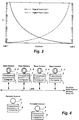
- each of the base stations includes a computer 1 that is coupled between the LAN and a transceiver 2.
- Each of the transceivers 2 has an antenna structure 3, 4 that is configured for effective near field coupling.
- Phase quadrature antennae generally are preferred for the base stations because of their superior directional insensitivity, but there may be applications in which a base station antenna with a greater directional sensitivity would be acceptable or even desirable.
- Each of the portable units typically includes some computational resources 6 (such as a lap top or hand-held computer), a transceiver 7 that is coupled to the computer 6, and an antenna 8 that is coupled to the transceiver 7 for effective near field coupling to a base station antenna 3, 4.
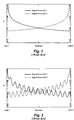
- near field coupled cellular systems have the advantage of providing more sharply defined cell boundaries than their far field coupled counterparts. This follows primarily from the relatively rapid spatial rate at which the near field strength decreases with increasing radial distance from the source.
- Fig. 3 illustrates the strong radial dependency of the near field strengths within a pair of adjacent cells. As will be evident, the rapid spatial rates at which the strength of these fields monotonically decay facilitate a monotonic transition from one cell to the next.
- the monotonicity of the cell-to-cell transitions in near field coupled systems is further enhanced because these systems typically operate at relatively low carrier frequencies.
- the carrier frequency of choice is on the order of 5MHz - 15MHz, which is roughly two orders of magnitude lower than the UHF carrier frequencies that are generally used in standard far field coupled systems.
- reflections occur only from the larger rf reflectors, such as the metal wall studs, that might be found in a typical indoor environment.
- near field coupled cellular systems generally provide monotonic cell-to-cell transitions, even when they are operated in reflective environments.
- a 5.3 MHz carrier suitably is modulated at data rates of up to about 250kbps using fsk (frequency shift keying) modulation.
- fsk frequency shift keying
- the base stations and the portable stations are half-duplex devices, so each of them suitably utilizes a single antenna structure for both transmitting and receiving.
- the sensitivity of these antennae is not very critical because the noise floor in the portion of the RF spectrum that generally is used to carry out this invention is determined primarily by the electromagnetic interference (EMI) that ordinarily exists in offices and similar environments.
- EMI electromagnetic interference
- loop antennae are favored, it is to be understood that provision advantageously is made to at least partially counter the directional sensitivity that such antennae tend to exhibit.
- each base station antenna has two loops 3 and 4 which are physically oriented at 90° with respect to each other.
- these two loops 3 and 4 are electrically driven in phase quadrature to cause rotation of the polarization of the signals they transmit.
- Reception is carried out by combining the signals that are sensed by the loops 3 and 4 in phase quadrature. If desired, a similar technique could be used to reduce the directional sensitivity of the loop antennae for the portable stations, but it generally is not necessary to do so because the base stations usually are sufficiently directionally insensitive in both their transmit and receive modes and the portable stations can be manually re-oriented, if need be, for satisfactory reception.
- the base stations (Fig. 5) and the portable stations (Fig. 6) suitably have the same basic architecture. Indeed, in this instance, apart from the provision that is made in the base stations for splitting and combining the signals that are applied to and sensed by their dual loop antennae, the base stations and the portables are architecturally identical. Accordingly, like reference numerals are used in Figs. 5 and 6 to identify like parts.
- the transceivers for the base stations and the portable stations each have a transmit/receive (T/R) switch 13 and 13', respectively, that is operated to selectively disable and enable the transmit channel within the transceiver while making and breaking, respectively, a connection between the antenna and its receive channel.
- T/R switches are well known and various types can be employed, so the switches 13 and 13' are depicted in simplified schematic form.
- the transmit channel of each of the transceivers includes a modulator 10 for modulating a suitable carrier signal in accordance with the data that is to be transmitted, such as by frequency shift modulation.
- the frequency of this modulated carrier may then be stepped down, such as by a frequency divider 11 or 11', to the carrier frequency that is desired for transmission.
- the transmit channel of each of the base station transceivers includes a ⁇ 4 frequency divider 11 because the divider 11 is a convenient means for producing the phase quadrature signals that are used for driving the dual loop base station antenna 3, 4.
- a similar frequency divider 11' is included in the transmit channel of each of the portable stations, but it is used in the portables merely to provide the architectural consistency that facilitates the use of common parts.
- phase quadrature outputs of the divider 11 are applied to the loops 3 and 4 of the base station antenna via respective class C amplifiers 12.
- Fig. 6 shows that just one of the outputs of the divider 11' is applied to the single loop 8 of the portable station antenna by a class C amplifier 12'.
- the receive channels of the base station transceivers also are only slightly more complex than the receive channels of the portable transceivers. Specifically, as shown in Fig. 5, the receive channel of each of the base station transceivers includes a quadrature combiner 20 for combining the signals that are sensed by the individual loops 3 and 4 of the dual loop base station antenna in phase quadrature with each other, thereby producing a directionally desensitized version of any incoming modulated carrier signal. Otherwise, however, the receive channels of the transceivers for the base stations and portable stations function essentially identically and share common parts.
- the incoming carrier signal typically is amplified by an amplifier 21, and this amplified signal then is filtered by a bandpass filter 22 to filter out extraneous noise.
- the modulated carrier signal then suitably is further amplified by another amplifier 23 before being demodulated by a demodulator 24 to recover the data that it carries.
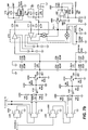
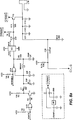
- Figs. 7a and 7b and Figs. 8a and 8b are circuit diagrams of a base station transceiver 2 and a portable station transceiver 7 , respectively, for one embodiment of the invention.
- these transceivers are substantially identical, with the exception that the base station transceiver 2 includes a second antenna loop for forming a dual loop antenna which is driven by the phase quadrature outputs of a phase splitter when the transceiver is operating in its transmit mode and from which incoming signals are received by a quadrature combiner when the transceiver is operating in its receive mode.
- the circuits shown in Figs. 7a and 7b and Figs. 8a and 8b will be described together, it being understood that certain portions of the description are applicable only to Fig. 7a and 7b.
- the transmit channel of the transceiver (sometimes referred to herein as a "transmitter”) includes a high frequency oscillator that is composed of a gate U1A, an inductor L1, and several associated capacitors.
- a Colpitts oscillator which nominally oscillates at four times (4X) the desired carrier frequency, is triggered into operation.
- the enable signal, XENABLE, for the oscillator typically is supplied by an associated computer (see Fig. 4) while the computer is operating in a transmit data mode.
- frequency shift keying (fsk) is used for modulating the carrier
- a phase-continuous technique is employed for shifting the output frequency of the oscillator back and forth between two preselected frequencies.
- the frequency shift could be effected with a voltage-variable capacitor
- the circuit of the transmitter employs a much simpler method. Specifically, it will be observed that the output frequency of the oscillator is largely determined by the inductor L1 and the combination of the capacitors C2 and C3. Therefore, if an extra capacitor is selectively inserted and removed from across the capacitor C2, the output frequency of the oscillator will shift accordingly.
- the fsk modulation of the signal supplied by the oscillator is performed by an inverse connected transistor T1 under the control of the data XDATA that are applied to its base via a gate U1B.
- the transistor T1 When turned on (i. e., switched into conduction) by the voltage at its base, the transistor T1 effectively connects the capacitor C1 in parallel with the parallel combination of capacitors C2 and C3, thereby reducing the output frequency of the oscillator.
- the upper frequency of the fsk modulated signal is determined primarily by the capacitors C2 and C3, while its lower frequency is largely determined by the parallel combination of capacitors C1, C2 and C3.
- An inverse-connected configuration is employed for the transistor T1 in order to lower its gain.
- transistor T1 may be connected in the conventional manner, its operation would be far less reliable because it would be at risk of being inadvertently switched into conduction (this risk is appreciable because a large signal on the collector of the transistor T1 would be coupled to its base via its base/collector capacitance C bc ). Inversely connecting transistor T1 causes it to act as a slow, relatively insensitive switch, so a substantial amount of base drive current is required to switch it into an "on" state. However, that is a small price to pay for the increased reliability that the inverse connection of the transistor T1 provides.
- the frequency of the fsk modulated signal is stepped-down by a divide by four ( ⁇ 4) frequency divider that is composed of a pair of cross-coupled D-type flip-flops U2A and U2B.
- the divider U2A/B not only steps down the carrier frequency of the fsk modulated signal to the 5.3 MHz carrier frequency that is desired for transmission, but it also functions in the base station transceiver as a phase splitter for splitting the fsk modulated signal into a pair of phase quadrature components.
- the phase quadrature outputs of the divider U2A/B are used for driving the two orthogonal loops L10 and L20 of the base station antenna in phase quadrature.
- Identical divider circuitry U2A/B is provided for the portable station to take advantage of the resulting parts commonality, but only one of its outputs is employed for driving the single loop antenna of the portable.
- the phase quadrature outputs of the divider U2A/B are coupled to class C driver transistors T10 and T20 for driving the antenna loops L10 and L20, respectively. Again, only one of these class C drivers is used in the portable.
- Transistors T10 and T20 typically provide a voltage swing of about 8v peak to peak for driving resonant antenna loops of the above-described type when the terminals VTRANS are held at about 5 volts by the voltage regulator VR.
- the voltage applied to the antenna loops L10 and L20 can be increased slightly by inserting a jumper at J1 and removing a jumper at J2, whereby the voltage regulator VR then is bypassed in favor of connecting the terminals VTRANS to the voltage supply V RAW
- the time constants of the RC networks R10, R11, C10 and R10, R21, C20 may need to be changed in a corresponding manner.
- a double-sided T/R switch comprised of FET arrays U30 and U40 is provided for isolating the receive channel of the base station transceiver from its antenna L10, L20 while the transceiver is operating in a transmit mode.
- a single-sided T/R switch performs the same function in the portable station transceiver.
- the strength of the signal that is applied to the antenna while it is transmitting would overload the receive channel, thereby charging various capacitors therein sufficiently to shift its bias points. If such overloading were permitted, each transmission by a transceiver would have to be followed by a substantial recovery time to permit the receive channel of that transceiver adequate time to restore itself to normal operation.
- the receive channel isolation that the T/R switch affords while such a transceiver is operating in a transmit mode greatly decreases the turn-around time of the transceiver.
- the FET arrays U30 and U40 respond sufficiently promptly when XENABLE returns to a high ("1") logic level (which signals the termination of the transmission) to restore the receive channel to a fully operational state in just a few bit times (assuming a data rate on the order of 250kbps).
- signals sensed by the antenna loops L10 and L20 are routed through the T/R switch to buffer amplifiers comprised of transistor amplifiers T30 and T40, respectively. Again, the single-sided equivalency of the receive channel of the portable station transceiver will be evident.
- the amplifiers T30 and T40 are biased so that when current is being drawn by capacitors C35 and C45 an output driving impedance of about 50 ⁇ is obtained at 5.3 MHz.
- this enables a network comprised of inductors L50 and L51, capacitors C50-C61 and resistor R50 to effectively function as a phase combiner for combining the 5.3 MHz signals sensed by the antenna loops L10 and L20 in phase quadrature with each other.
- a phase combiner for combining the 5.3 MHz signals sensed by the antenna loops L10 and L20 in phase quadrature with each other.
- the received signal is next is applied to an IF amplifier/detector U70.
- U70 suitably is a Signetics NE614, which is a low power FM IF/quadrature detector with limiting and signal strength outputs, as well as provision for external bandpass filtering. No heterodyne conversion is necessary, because (i) adequate gain is available from U70 at 5.3 MHz, (ii) the bandwidth requirements are not too restrictive, and (iii) no frequency agility is required in this application.
- the inductor L70 and the capacitors C72, C73 form a bandpass filter, while the inductor L75, the resistor R75, and the capacitors C75, C76 and C77 form a phase shifter for the internal quadrature detector of U70.
- the internal quadrature detector of the Signetics NE614 device provides about 1 volt p-p output signal at pin 7 for a 400 kHz deviation of the input signal.
- This signal is buffered by transistor T80, and then is passed through a thresholding comparator U80, with a slight amount of hysteresis, to recover the baseband data (i. e., the data carried by the modulated carrier).
- This baseband data, RDATA produces a serial data stream that is loaded into a suitable computer to complete the cellular phase of the data transfer task.
- the use of the Signetics NE614 device as the IF amplifier/detector U70 led to the use the buffer amplifier T80 because the output impedance at pin 7 of the Signetics device is sufficiently high to cause severe signal degradation if it was used to directly drive even the small capacitance at the input of the comparator U80.
- the transistor T80 therefore, performs the beneficial function of sharpening the received signal transitions.
- the buffer amplifiers T30 and T40, along with the quadrature network (in the base station transceiver) are employed to create a deliberate impedance mismatch at the input to the FM IF/quadrature detector U70.
- the mismatch is created because the Signetics NE614 device has shown a tendency to oscillate at the frequencies that are of interest. Hence, at the operating frequencies that are favored for carrying out this invention, there often is enough stray coupling capacitance between the IF output and the IF input of the Signetics device to cause oscillation to occur.
- the impedance mismatch at the input to U70 is designed to suppress this unwanted oscillation by providing a relatively low impedance shunt path for the feedback that tends to cause such oscillation.
- Transmitters and receivers constructed in accordance with the invention have shown great promise when a carrier frequency of 5.3 MHz was used, and the power level was chosen to stay within U.S. FCC regulations for license-free operation.
- the resulting near field pattern has been found to have a useful range of about 12-15 feet (3.66-4.58m), and data rates of 250kbps have been achieved. Peaks and nulls are not evident in this system, except for those that are caused by the directional sensitivity of the single loop antennae of the portable transceivers.
- the directional sensitivity of the portable transceivers typically is not a performance issue, except when such a transceiver is located near a cell boundary.
- a quadrupole source is the functional equivalent of two closely spaced dipoles, acting in opposite directions.
- the resulting field therefore, has a near field component which decays as 1/r4.
- several sources can be grouped into a single cell, so as to tailor the near field pattern to a desired shape. Such grouping may include several dipoles or several quadrupoles, or a combination of both, driven from the same source, so as to improve the uniformity of coverage within a cell.
- the loop antennae of the above described embodiments of the invention are especially well suited for use in rooms of comparable length and width, such as an ordinary office. However, it sometimes may be desirable to support communications between a base station and portable stations in a long narrow area, such as in a hallway or corridor. At first blush, it may be thought that a long wire antenna would be an attractive option for near field coupling in a hallway or similar area. However, such an antenna tends to causes interference with adjacent cells, and is subject to restrictive governmental radio emission standards. In addition, long wire antennae generally have nulls because of the standing wave patterns that are generated with them when they are excited by RF signals, so they are ill-suited to providing the uniform coverage that is desired.
- this invention deals with the problem of providing near field coupling coverage within these more irregularly shaped cells by equipping the base station transceiver 2 with a twisted loop antenna 50.
- this single loop antenna 50 is composed of two wires that are twisted together or otherwise overlapped as at 52 to effectively subdivide the antenna 50 into a series of oppositely polled dipole segments 54.
- Each of these segments 54 is shorter than the wavelength ( ⁇ ) of the rf energy that is applied to the antenna by the transceiver 12. Indeed, they typically are on the order of 1/4 ⁇ long.
- the antenna 50 is terminated by a balancing resistor 51 to provide a sink for the drive current that is applied thereto when the transceiver 12 is operating in its transmit mode, thereby suppressing signal reflections and the standing wave patterns that such reflections would cause.
- the antenna 50 may be fabricated to contain one or more twists of the two wires, or it may be formed by a simple crossing of the wires, so it is to be understood that "crisscrossing" is used herein as a generic description of such an arrangement.
- the antenna 50 may be installed in a straight line, for example to provide single cell coverage of a hallway or the like. Or, it can be installed in a curved, dog-legged, or zig-zag pattern to cover areas of various shapes and sizes.
Landscapes
- Engineering & Computer Science (AREA)
- Computer Networks & Wireless Communication (AREA)
- Signal Processing (AREA)
- Mobile Radio Communication Systems (AREA)
- Near-Field Transmission Systems (AREA)
Applications Claiming Priority (2)
| Application Number | Priority Date | Filing Date | Title |
|---|---|---|---|
| US07/984,821 US5437057A (en) | 1992-12-03 | 1992-12-03 | Wireless communications using near field coupling |
| US984821 | 1992-12-03 |
Publications (3)
| Publication Number | Publication Date |
|---|---|
| EP0600695A2 true EP0600695A2 (fr) | 1994-06-08 |
| EP0600695A3 EP0600695A3 (fr) | 1995-01-18 |
| EP0600695B1 EP0600695B1 (fr) | 2001-10-04 |
Family
ID=25530917
Family Applications (1)
| Application Number | Title | Priority Date | Filing Date |
|---|---|---|---|
| EP93309505A Expired - Lifetime EP0600695B1 (fr) | 1992-12-03 | 1993-11-29 | Communications sans fil utilisant l'accouplement à courte distance |
Country Status (4)
| Country | Link |
|---|---|
| US (1) | US5437057A (fr) |
| EP (1) | EP0600695B1 (fr) |
| JP (1) | JP2528259B2 (fr) |
| DE (1) | DE69330861T2 (fr) |
Cited By (5)
| Publication number | Priority date | Publication date | Assignee | Title |
|---|---|---|---|---|
| EP0872032B1 (fr) * | 1995-05-18 | 2003-11-26 | Aura Communications, Inc. | Systeme de communication magnetique de courte portee |
| WO2006027725A1 (fr) * | 2004-09-08 | 2006-03-16 | Koninklijke Philips Electronics N.V. | Appariement securise pour dispositifs de communication filaires ou sans fil |
| EP1653632A1 (fr) | 2004-10-29 | 2006-05-03 | Sony Deutschland GmbH | Procédé de fonctionnement d'un système de communication du champ proche |
| GB2443670A (en) * | 2006-11-13 | 2008-05-14 | Steven Martin Hudson | Transmitting information using electrically isolated conductive bodies, which may be aircraft |
| US8639395B2 (en) | 2006-11-13 | 2014-01-28 | Steven Martin Hudson | Conductive bodies |
Families Citing this family (135)
| Publication number | Priority date | Publication date | Assignee | Title |
|---|---|---|---|---|
| US5912925A (en) | 1995-05-18 | 1999-06-15 | Aura Communications, Inc. | Diversity circuit for magnetic communication system |
| US5982764A (en) * | 1995-05-18 | 1999-11-09 | Aura Communications, Inc. | Time-multiplexed short-range magnetic communications |
| US5739791A (en) * | 1995-11-06 | 1998-04-14 | Lxe Inc. | Antenna for use with a radio installed in an expansion slot of a computer system |
| US6134420A (en) * | 1996-11-01 | 2000-10-17 | Plantronics, Inc. | Vector measuring aerial arrays for magnetic induction communication systems |
| US6061030A (en) * | 1996-11-01 | 2000-05-09 | Plantronics, Inc. | Aerial arrays for magnetic induction communication systems having limited power supplies |
| US6404755B1 (en) | 1996-11-07 | 2002-06-11 | Harris Broadband Wireless Access, Inc. | Multi-level information mapping system and method |
| US6016313A (en) * | 1996-11-07 | 2000-01-18 | Wavtrace, Inc. | System and method for broadband millimeter wave data communication |
| US6560461B1 (en) | 1997-08-04 | 2003-05-06 | Mundi Fomukong | Authorized location reporting paging system |
| US6243592B1 (en) | 1997-10-23 | 2001-06-05 | Kyocera Corporation | Portable radio |
| US6275539B1 (en) * | 1998-07-20 | 2001-08-14 | Lear Automotive Dearborn, Inc. | System and method for modulating a frequency signal |
| US6101371A (en) * | 1998-09-12 | 2000-08-08 | Lucent Technologies, Inc. | Article comprising an inductor |
| US6336031B1 (en) | 1998-12-22 | 2002-01-01 | Nortel Networks Limited | Wireless data transmission over quasi-static electric potential fields |
| US6424820B1 (en) * | 1999-04-02 | 2002-07-23 | Interval Research Corporation | Inductively coupled wireless system and method |
| US6233336B1 (en) | 1999-04-30 | 2001-05-15 | Gai-Tronics Corporation | Inductive coupling interface for electronic device |
| US7099621B1 (en) * | 1999-06-25 | 2006-08-29 | Cocomo Mb Communications, Inc. | Electromagnetic field communications system for wireless networks |
| US6349116B1 (en) * | 1999-10-14 | 2002-02-19 | Wherenet Corp. | Data communication system harnessing frequency shift keyed magnetic field |
| US6536658B1 (en) * | 1999-12-28 | 2003-03-25 | Ncr Corporation | Method and apparatus for operating a retail terminal having a proximity detector that is operable to ascertain movement and distance of a consumer relative to the retail terminal |
| US6853687B2 (en) | 2000-01-12 | 2005-02-08 | Wherenet Corp | Proximity-based magnetic field generator for controlling operation of RF burst-transmitting tags of geolocation system |
| US7532901B1 (en) | 2001-03-16 | 2009-05-12 | Radeum, Inc. | Methods and apparatus to detect location and orientation in an inductive system |
| US7307595B2 (en) * | 2004-12-21 | 2007-12-11 | Q-Track Corporation | Near field location system and method |
| DE10245450B4 (de) * | 2002-09-27 | 2018-06-14 | Schleifring Gmbh | Vorrichtung und Verfahren zur Übertragung digitaler Signale zwischen beweglichen Einheiten mit variabler Übertragungsrate |
| US7325180B2 (en) * | 2003-11-26 | 2008-01-29 | Carnegie Mellon University | System and method to test integrated circuits on a wafer |
| US7933554B2 (en) * | 2004-11-04 | 2011-04-26 | The United States Of America As Represented By The Secretary Of The Army | Systems and methods for short range wireless communication |
| US7825543B2 (en) * | 2005-07-12 | 2010-11-02 | Massachusetts Institute Of Technology | Wireless energy transfer |
| KR101118710B1 (ko) | 2005-07-12 | 2012-03-13 | 메사추세츠 인스티튜트 오브 테크놀로지 | 무선 비-방사성 에너지 전달 |
| JP4813171B2 (ja) * | 2005-12-16 | 2011-11-09 | 株式会社豊田自動織機 | ステータの製造方法及び製造装置 |
| JP4855150B2 (ja) * | 2006-06-09 | 2012-01-18 | 株式会社トプコン | 眼底観察装置、眼科画像処理装置及び眼科画像処理プログラム |
| US8041227B2 (en) * | 2006-11-16 | 2011-10-18 | Silicon Laboratories Inc. | Apparatus and method for near-field communication |
| US9670694B2 (en) * | 2007-04-12 | 2017-06-06 | Utc Fire & Security Americas Corporation, Inc. | Restricted range lockbox, access device and methods |
| US8400913B2 (en) * | 2007-05-23 | 2013-03-19 | Microsoft Corporation | Method for optimizing near field links |
| US9421388B2 (en) | 2007-06-01 | 2016-08-23 | Witricity Corporation | Power generation for implantable devices |
| US8805530B2 (en) * | 2007-06-01 | 2014-08-12 | Witricity Corporation | Power generation for implantable devices |
| DE102007028234A1 (de) * | 2007-06-20 | 2008-12-24 | Siemens Audiologische Technik Gmbh | Anordnung von Geräten mit mindestens einem Sender und Verfahren zur Verbesserung der Empfangsfeldstärke |
| JP5050986B2 (ja) * | 2008-04-30 | 2012-10-17 | ソニー株式会社 | 通信システム |
| WO2009140506A1 (fr) * | 2008-05-14 | 2009-11-19 | Massachusetts Institute Of Technology | Transfert d'énergie sans fil, comprenant une amélioration vis-à-vis d'une interférence |
| US20110156494A1 (en) * | 2008-08-25 | 2011-06-30 | Governing Dynamics Llc | Wireless Energy Transfer System |
| WO2010036980A1 (fr) | 2008-09-27 | 2010-04-01 | Witricity Corporation | Systèmes de transfert d'énergie sans fil |
| US8772973B2 (en) | 2008-09-27 | 2014-07-08 | Witricity Corporation | Integrated resonator-shield structures |
| US8461721B2 (en) | 2008-09-27 | 2013-06-11 | Witricity Corporation | Wireless energy transfer using object positioning for low loss |
| US8907531B2 (en) | 2008-09-27 | 2014-12-09 | Witricity Corporation | Wireless energy transfer with variable size resonators for medical applications |
| US8723366B2 (en) | 2008-09-27 | 2014-05-13 | Witricity Corporation | Wireless energy transfer resonator enclosures |
| US8963488B2 (en) | 2008-09-27 | 2015-02-24 | Witricity Corporation | Position insensitive wireless charging |
| US8587155B2 (en) | 2008-09-27 | 2013-11-19 | Witricity Corporation | Wireless energy transfer using repeater resonators |
| US8569914B2 (en) | 2008-09-27 | 2013-10-29 | Witricity Corporation | Wireless energy transfer using object positioning for improved k |
| US8957549B2 (en) | 2008-09-27 | 2015-02-17 | Witricity Corporation | Tunable wireless energy transfer for in-vehicle applications |
| US9601270B2 (en) | 2008-09-27 | 2017-03-21 | Witricity Corporation | Low AC resistance conductor designs |
| US8669676B2 (en) | 2008-09-27 | 2014-03-11 | Witricity Corporation | Wireless energy transfer across variable distances using field shaping with magnetic materials to improve the coupling factor |
| US8686598B2 (en) | 2008-09-27 | 2014-04-01 | Witricity Corporation | Wireless energy transfer for supplying power and heat to a device |
| US8912687B2 (en) | 2008-09-27 | 2014-12-16 | Witricity Corporation | Secure wireless energy transfer for vehicle applications |
| US9396867B2 (en) | 2008-09-27 | 2016-07-19 | Witricity Corporation | Integrated resonator-shield structures |
| US8629578B2 (en) | 2008-09-27 | 2014-01-14 | Witricity Corporation | Wireless energy transfer systems |
| US9160203B2 (en) | 2008-09-27 | 2015-10-13 | Witricity Corporation | Wireless powered television |
| US9184595B2 (en) | 2008-09-27 | 2015-11-10 | Witricity Corporation | Wireless energy transfer in lossy environments |
| US9105959B2 (en) | 2008-09-27 | 2015-08-11 | Witricity Corporation | Resonator enclosure |
| US8461720B2 (en) | 2008-09-27 | 2013-06-11 | Witricity Corporation | Wireless energy transfer using conducting surfaces to shape fields and reduce loss |
| US8643326B2 (en) | 2008-09-27 | 2014-02-04 | Witricity Corporation | Tunable wireless energy transfer systems |
| US9246336B2 (en) | 2008-09-27 | 2016-01-26 | Witricity Corporation | Resonator optimizations for wireless energy transfer |
| US9106203B2 (en) | 2008-09-27 | 2015-08-11 | Witricity Corporation | Secure wireless energy transfer in medical applications |
| US8946938B2 (en) | 2008-09-27 | 2015-02-03 | Witricity Corporation | Safety systems for wireless energy transfer in vehicle applications |
| US9318922B2 (en) | 2008-09-27 | 2016-04-19 | Witricity Corporation | Mechanically removable wireless power vehicle seat assembly |
| US9577436B2 (en) | 2008-09-27 | 2017-02-21 | Witricity Corporation | Wireless energy transfer for implantable devices |
| US8552592B2 (en) | 2008-09-27 | 2013-10-08 | Witricity Corporation | Wireless energy transfer with feedback control for lighting applications |
| US9515494B2 (en) | 2008-09-27 | 2016-12-06 | Witricity Corporation | Wireless power system including impedance matching network |
| US8598743B2 (en) | 2008-09-27 | 2013-12-03 | Witricity Corporation | Resonator arrays for wireless energy transfer |
| US8482158B2 (en) | 2008-09-27 | 2013-07-09 | Witricity Corporation | Wireless energy transfer using variable size resonators and system monitoring |
| US9544683B2 (en) | 2008-09-27 | 2017-01-10 | Witricity Corporation | Wirelessly powered audio devices |
| US8466583B2 (en) | 2008-09-27 | 2013-06-18 | Witricity Corporation | Tunable wireless energy transfer for outdoor lighting applications |
| US8410636B2 (en) | 2008-09-27 | 2013-04-02 | Witricity Corporation | Low AC resistance conductor designs |
| US9744858B2 (en) | 2008-09-27 | 2017-08-29 | Witricity Corporation | System for wireless energy distribution in a vehicle |
| US8922066B2 (en) | 2008-09-27 | 2014-12-30 | Witricity Corporation | Wireless energy transfer with multi resonator arrays for vehicle applications |
| US9601261B2 (en) | 2008-09-27 | 2017-03-21 | Witricity Corporation | Wireless energy transfer using repeater resonators |
| US8947186B2 (en) | 2008-09-27 | 2015-02-03 | Witricity Corporation | Wireless energy transfer resonator thermal management |
| US8324759B2 (en) | 2008-09-27 | 2012-12-04 | Witricity Corporation | Wireless energy transfer using magnetic materials to shape field and reduce loss |
| US8497601B2 (en) | 2008-09-27 | 2013-07-30 | Witricity Corporation | Wireless energy transfer converters |
| US8476788B2 (en) | 2008-09-27 | 2013-07-02 | Witricity Corporation | Wireless energy transfer with high-Q resonators using field shaping to improve K |
| US8901779B2 (en) | 2008-09-27 | 2014-12-02 | Witricity Corporation | Wireless energy transfer with resonator arrays for medical applications |
| US9065423B2 (en) | 2008-09-27 | 2015-06-23 | Witricity Corporation | Wireless energy distribution system |
| US8400017B2 (en) | 2008-09-27 | 2013-03-19 | Witricity Corporation | Wireless energy transfer for computer peripheral applications |
| US8928276B2 (en) | 2008-09-27 | 2015-01-06 | Witricity Corporation | Integrated repeaters for cell phone applications |
| US8692410B2 (en) | 2008-09-27 | 2014-04-08 | Witricity Corporation | Wireless energy transfer with frequency hopping |
| US8937408B2 (en) | 2008-09-27 | 2015-01-20 | Witricity Corporation | Wireless energy transfer for medical applications |
| US8692412B2 (en) | 2008-09-27 | 2014-04-08 | Witricity Corporation | Temperature compensation in a wireless transfer system |
| US8304935B2 (en) | 2008-09-27 | 2012-11-06 | Witricity Corporation | Wireless energy transfer using field shaping to reduce loss |
| US8471410B2 (en) | 2008-09-27 | 2013-06-25 | Witricity Corporation | Wireless energy transfer over distance using field shaping to improve the coupling factor |
| US8461722B2 (en) | 2008-09-27 | 2013-06-11 | Witricity Corporation | Wireless energy transfer using conducting surfaces to shape field and improve K |
| US8901778B2 (en) | 2008-09-27 | 2014-12-02 | Witricity Corporation | Wireless energy transfer with variable size resonators for implanted medical devices |
| US9035499B2 (en) | 2008-09-27 | 2015-05-19 | Witricity Corporation | Wireless energy transfer for photovoltaic panels |
| US8487480B1 (en) | 2008-09-27 | 2013-07-16 | Witricity Corporation | Wireless energy transfer resonator kit |
| US9093853B2 (en) | 2008-09-27 | 2015-07-28 | Witricity Corporation | Flexible resonator attachment |
| US8933594B2 (en) | 2008-09-27 | 2015-01-13 | Witricity Corporation | Wireless energy transfer for vehicles |
| US9601266B2 (en) | 2008-09-27 | 2017-03-21 | Witricity Corporation | Multiple connected resonators with a single electronic circuit |
| US8587153B2 (en) | 2008-09-27 | 2013-11-19 | Witricity Corporation | Wireless energy transfer using high Q resonators for lighting applications |
| US8441154B2 (en) | 2008-09-27 | 2013-05-14 | Witricity Corporation | Multi-resonator wireless energy transfer for exterior lighting |
| EP2345100B1 (fr) | 2008-10-01 | 2018-12-05 | Massachusetts Institute of Technology | Transfert d'énergie sans fil en champ proche efficace utilisant des variations de système adiabatique |
| US8362961B2 (en) * | 2009-11-03 | 2013-01-29 | Honeywell International Inc. | Modulated antenna for wireless communications |
| US9602168B2 (en) | 2010-08-31 | 2017-03-21 | Witricity Corporation | Communication in wireless energy transfer systems |
| US9948145B2 (en) | 2011-07-08 | 2018-04-17 | Witricity Corporation | Wireless power transfer for a seat-vest-helmet system |
| CA2844062C (fr) | 2011-08-04 | 2017-03-28 | Witricity Corporation | Architectures d'electricite sans fil reglables |
| SG11201400409XA (en) * | 2011-09-07 | 2014-04-28 | Solace Power Inc | Wireless electric field power transmission system and method |
| JP6185472B2 (ja) | 2011-09-09 | 2017-08-23 | ワイトリシティ コーポレーションWitricity Corporation | ワイヤレスエネルギー伝送システムにおける異物検出 |
| US20130062966A1 (en) | 2011-09-12 | 2013-03-14 | Witricity Corporation | Reconfigurable control architectures and algorithms for electric vehicle wireless energy transfer systems |
| US9318257B2 (en) | 2011-10-18 | 2016-04-19 | Witricity Corporation | Wireless energy transfer for packaging |
| HK1200602A1 (en) | 2011-11-04 | 2015-08-07 | WiTricity公司 | Wireless energy transfer modeling tool |
| WO2013113017A1 (fr) | 2012-01-26 | 2013-08-01 | Witricity Corporation | Transfert d'énergie sans fil à champs réduits |
| US9343922B2 (en) | 2012-06-27 | 2016-05-17 | Witricity Corporation | Wireless energy transfer for rechargeable batteries |
| US9287607B2 (en) | 2012-07-31 | 2016-03-15 | Witricity Corporation | Resonator fine tuning |
| US9595378B2 (en) | 2012-09-19 | 2017-03-14 | Witricity Corporation | Resonator enclosure |
| WO2014063159A2 (fr) | 2012-10-19 | 2014-04-24 | Witricity Corporation | Détection de corps étranger dans des systèmes de transfert d'énergie sans fil |
| US9842684B2 (en) | 2012-11-16 | 2017-12-12 | Witricity Corporation | Systems and methods for wireless power system with improved performance and/or ease of use |
| EP3039770B1 (fr) | 2013-08-14 | 2020-01-22 | WiTricity Corporation | Réglage d'impédance |
| US9780573B2 (en) | 2014-02-03 | 2017-10-03 | Witricity Corporation | Wirelessly charged battery system |
| US9952266B2 (en) | 2014-02-14 | 2018-04-24 | Witricity Corporation | Object detection for wireless energy transfer systems |
| US9842687B2 (en) | 2014-04-17 | 2017-12-12 | Witricity Corporation | Wireless power transfer systems with shaped magnetic components |
| WO2015161035A1 (fr) | 2014-04-17 | 2015-10-22 | Witricity Corporation | Systèmes de transfert d'énergie sans fil à ouvertures dans un blindage |
| US9837860B2 (en) | 2014-05-05 | 2017-12-05 | Witricity Corporation | Wireless power transmission systems for elevators |
| WO2015171910A1 (fr) | 2014-05-07 | 2015-11-12 | Witricity Corporation | Détection de corps étrangers dans des systèmes de transfert de puissance sans fil |
| US9954375B2 (en) | 2014-06-20 | 2018-04-24 | Witricity Corporation | Wireless power transfer systems for surfaces |
| CA2953621A1 (fr) | 2014-06-26 | 2015-12-30 | Solace Power Inc. | Systeme de transmission de puissance de champ electrique sans fil, emetteur et recepteur pour ce dernier et procede de transfert sans fil de puissance |
| WO2016007674A1 (fr) | 2014-07-08 | 2016-01-14 | Witricity Corporation | Équilibrage de résonateurs dans des systèmes de transfert d'énergie sans fil |
| US10574091B2 (en) | 2014-07-08 | 2020-02-25 | Witricity Corporation | Enclosures for high power wireless power transfer systems |
| CN106463831B (zh) * | 2014-07-30 | 2020-09-18 | 瑞萨电子株式会社 | 环形天线 |
| WO2016033697A1 (fr) | 2014-09-05 | 2016-03-10 | Solace Power Inc. | Système de transfert de puissance de champ électrique sans fil, procédé, émetteur et récepteur associés |
| US9735822B1 (en) * | 2014-09-16 | 2017-08-15 | Amazon Technologies, Inc. | Low specific absorption rate dual-band antenna structure |
| US9843217B2 (en) | 2015-01-05 | 2017-12-12 | Witricity Corporation | Wireless energy transfer for wearables |
| US10248899B2 (en) | 2015-10-06 | 2019-04-02 | Witricity Corporation | RFID tag and transponder detection in wireless energy transfer systems |
| EP3362804B1 (fr) | 2015-10-14 | 2024-01-17 | WiTricity Corporation | Détection de phase et d'amplitude dans des systèmes de transfert d'énergie sans fil |
| WO2017070227A1 (fr) | 2015-10-19 | 2017-04-27 | Witricity Corporation | Détection d'objet étranger dans des systèmes de transfert d'énergie sans fil |
| WO2017070009A1 (fr) | 2015-10-22 | 2017-04-27 | Witricity Corporation | Accord dynamique dans des systèmes de transfert d'énergie sans fil |
| US10075019B2 (en) | 2015-11-20 | 2018-09-11 | Witricity Corporation | Voltage source isolation in wireless power transfer systems |
| CN109075613B (zh) | 2016-02-02 | 2022-05-31 | 韦特里西提公司 | 控制无线电力传输系统 |
| WO2017139406A1 (fr) | 2016-02-08 | 2017-08-17 | Witricity Corporation | Commande de condensateur pwm |
| WO2019006376A1 (fr) | 2017-06-29 | 2019-01-03 | Witricity Corporation | Protection et commande de systèmes d'alimentation sans fil |
| JP7248249B2 (ja) * | 2018-08-17 | 2023-03-29 | 慶應義塾 | 通信回路、及び通信方法 |
| US11099222B2 (en) * | 2019-01-20 | 2021-08-24 | Christopher T. Baumgartner | Near-field electrostatic communications system |
| US12024039B2 (en) | 2021-12-07 | 2024-07-02 | Arnold Chase | Vehicle self-centered charging system |
Family Cites Families (7)
| Publication number | Priority date | Publication date | Assignee | Title |
|---|---|---|---|---|
| JPS6133A (ja) * | 1984-06-08 | 1986-01-06 | Mitsubishi Rayon Co Ltd | メタリルアルコ−ルの製造法 |
| US4747158A (en) * | 1985-01-22 | 1988-05-24 | Data Products New England, Inc. | Cordless communications system |
| US4584707A (en) * | 1985-01-22 | 1986-04-22 | Dataproducts New England, Inc. | Cordless communications system |
| JPH0746877B2 (ja) * | 1985-12-11 | 1995-05-17 | 株式会社日立製作所 | 移動無線通信システム |
| JPH02207361A (ja) * | 1989-02-08 | 1990-08-17 | Shimizu Corp | 誘導無線を利用した室内データ通信システム |
| SE465992B (sv) * | 1990-04-10 | 1991-11-25 | Ericsson Telefon Ab L M | Mobiltelefonisystem avsett att brukas av abonnenter inomhus och utomhus |
| US5181200A (en) * | 1990-10-29 | 1993-01-19 | International Business Machines Corporation | Handoff method and apparatus for mobile wireless workstation |
-
1992
- 1992-12-03 US US07/984,821 patent/US5437057A/en not_active Expired - Lifetime
-
1993
- 1993-11-19 JP JP5290264A patent/JP2528259B2/ja not_active Expired - Lifetime
- 1993-11-29 EP EP93309505A patent/EP0600695B1/fr not_active Expired - Lifetime
- 1993-11-29 DE DE69330861T patent/DE69330861T2/de not_active Expired - Lifetime
Cited By (11)
| Publication number | Priority date | Publication date | Assignee | Title |
|---|---|---|---|---|
| EP0872032B1 (fr) * | 1995-05-18 | 2003-11-26 | Aura Communications, Inc. | Systeme de communication magnetique de courte portee |
| WO2006027725A1 (fr) * | 2004-09-08 | 2006-03-16 | Koninklijke Philips Electronics N.V. | Appariement securise pour dispositifs de communication filaires ou sans fil |
| US8813188B2 (en) | 2004-09-08 | 2014-08-19 | Koninklijke Philips N.V. | Secure pairing for wired or wireless communications devices |
| EP1653632A1 (fr) | 2004-10-29 | 2006-05-03 | Sony Deutschland GmbH | Procédé de fonctionnement d'un système de communication du champ proche |
| US7734307B2 (en) | 2004-10-29 | 2010-06-08 | Sony Deutschland Gmbh | Method for operating a near field communication system |
| EP2840717A1 (fr) * | 2004-10-29 | 2015-02-25 | Sony Deutschland Gmbh | Procédé pour faire fonctionner un système de communication en champ proche |
| EP3154206A1 (fr) * | 2004-10-29 | 2017-04-12 | Sony Deutschland Gmbh | Procédé pour faire fonctionner un système de communication en champ proche |
| GB2443670A (en) * | 2006-11-13 | 2008-05-14 | Steven Martin Hudson | Transmitting information using electrically isolated conductive bodies, which may be aircraft |
| GB2443670B (en) * | 2006-11-13 | 2011-03-23 | Steven Martin Hudson | Aircraft and conductive bodies |
| US8639395B2 (en) | 2006-11-13 | 2014-01-28 | Steven Martin Hudson | Conductive bodies |
| US8965277B2 (en) | 2006-11-13 | 2015-02-24 | Steven Martin Hudson | Aircraft and conductive bodies |
Also Published As
| Publication number | Publication date |
|---|---|
| JPH06233348A (ja) | 1994-08-19 |
| EP0600695B1 (fr) | 2001-10-04 |
| EP0600695A3 (fr) | 1995-01-18 |
| DE69330861T2 (de) | 2002-03-28 |
| DE69330861D1 (de) | 2001-11-08 |
| JP2528259B2 (ja) | 1996-08-28 |
| US5437057A (en) | 1995-07-25 |
Similar Documents
| Publication | Publication Date | Title |
|---|---|---|
| EP0600695B1 (fr) | Communications sans fil utilisant l'accouplement à courte distance | |
| EP2051397B1 (fr) | Coupleur de champ électrique haute fréquence, système de communication et appareil de communication | |
| US8023890B2 (en) | Communication system, communication apparatus, and electric-field-coupling antenna | |
| EP1926223A2 (fr) | Système et appareil de communication | |
| GB2221820A (en) | Polarization diversity radio communication system | |
| US5280631A (en) | Polarization diversity system suitable for radio communication in indoor space | |
| EP1672804B1 (fr) | Appareil de communication radio | |
| KR101091393B1 (ko) | 안테나 장치 및 무선 통신 장치 | |
| JP2003523121A (ja) | トランスポンダ用アンテナ | |
| US20040087345A1 (en) | Wireless digital data transmission from a passive transceiver | |
| KR20240136921A (ko) | 공명 전력 신호 및 유도 전력 신호를 전송할 수 있는 하이브리드 무선 전력 전송 장치 및 이를 포함하는 하이브리드 무선 전력 전송 시스템 | |
| Araiza | Wireless transmission of power for sensors in context aware spaces | |
| CN210222762U (zh) | 超高频rfid读写器、超高频rfid读写系统 | |
| Jorgensen et al. | Retrodirective antenna systems for wireless communications | |
| KR20180104973A (ko) | 근거리 무선 통신 안테나를 포함하는 무선 전력 송신기 | |
| JP6987385B2 (ja) | アレイアンテナおよび無線通信システム | |
| EP4543139A1 (fr) | Appareil et dispositif de communication | |
| EP1983606A1 (fr) | Antenne à bande-boucle multiple, à polarisation double, et méthodologie associée, pour dispositif radio | |
| CN100542061C (zh) | 无线通信设备 | |
| Gyan et al. | Multistate Planar OAM Antenna for Reduced Inter-Modal Interference | |
| JPH11261331A (ja) | 非接触型icカードシステムの質問器アンテナ | |
| KR20240009292A (ko) | 통신 장치 | |
| JP2000068876A (ja) | 通信システム | |
| Surugiu et al. | Microwave monitoring systems–designing slot coupled patch antenna with linear polarization | |
| KR20240009294A (ko) | 통신 장치 |
Legal Events
| Date | Code | Title | Description |
|---|---|---|---|
| PUAI | Public reference made under article 153(3) epc to a published international application that has entered the european phase |
Free format text: ORIGINAL CODE: 0009012 |
|
| AK | Designated contracting states |
Kind code of ref document: A2 Designated state(s): DE FR GB |
|
| PUAL | Search report despatched |
Free format text: ORIGINAL CODE: 0009013 |
|
| RHK1 | Main classification (correction) |
Ipc: H04Q 7/22 |
|
| AK | Designated contracting states |
Kind code of ref document: A3 Designated state(s): DE FR GB |
|
| 17P | Request for examination filed |
Effective date: 19950718 |
|
| 17Q | First examination report despatched |
Effective date: 19990520 |
|
| GRAG | Despatch of communication of intention to grant |
Free format text: ORIGINAL CODE: EPIDOS AGRA |
|
| GRAG | Despatch of communication of intention to grant |
Free format text: ORIGINAL CODE: EPIDOS AGRA |
|
| GRAG | Despatch of communication of intention to grant |
Free format text: ORIGINAL CODE: EPIDOS AGRA |
|
| GRAH | Despatch of communication of intention to grant a patent |
Free format text: ORIGINAL CODE: EPIDOS IGRA |
|
| GRAH | Despatch of communication of intention to grant a patent |
Free format text: ORIGINAL CODE: EPIDOS IGRA |
|
| GRAA | (expected) grant |
Free format text: ORIGINAL CODE: 0009210 |
|
| AK | Designated contracting states |
Kind code of ref document: B1 Designated state(s): DE FR GB |
|
| REF | Corresponds to: |
Ref document number: 69330861 Country of ref document: DE Date of ref document: 20011108 |
|
| REG | Reference to a national code |
Ref country code: GB Ref legal event code: IF02 |
|
| ET | Fr: translation filed | ||
| PLBE | No opposition filed within time limit |
Free format text: ORIGINAL CODE: 0009261 |
|
| 26N | No opposition filed | ||
| PGFP | Annual fee paid to national office [announced via postgrant information from national office to epo] |
Ref country code: DE Payment date: 20121025 Year of fee payment: 20 |
|
| PGFP | Annual fee paid to national office [announced via postgrant information from national office to epo] |
Ref country code: GB Payment date: 20121025 Year of fee payment: 20 |
|
| PGFP | Annual fee paid to national office [announced via postgrant information from national office to epo] |
Ref country code: FR Payment date: 20130107 Year of fee payment: 20 |
|
| REG | Reference to a national code |
Ref country code: DE Ref legal event code: R071 Ref document number: 69330861 Country of ref document: DE |
|
| REG | Reference to a national code |
Ref country code: GB Ref legal event code: PE20 Expiry date: 20131128 |
|
| PG25 | Lapsed in a contracting state [announced via postgrant information from national office to epo] |
Ref country code: GB Free format text: LAPSE BECAUSE OF EXPIRATION OF PROTECTION Effective date: 20131128 Ref country code: DE Free format text: LAPSE BECAUSE OF EXPIRATION OF PROTECTION Effective date: 20131130 |