EP0600770A1 - Abwickelvorrichtung für biegsamen Schlauch - Google Patents
Abwickelvorrichtung für biegsamen Schlauch Download PDFInfo
- Publication number
- EP0600770A1 EP0600770A1 EP93402861A EP93402861A EP0600770A1 EP 0600770 A1 EP0600770 A1 EP 0600770A1 EP 93402861 A EP93402861 A EP 93402861A EP 93402861 A EP93402861 A EP 93402861A EP 0600770 A1 EP0600770 A1 EP 0600770A1
- Authority
- EP
- European Patent Office
- Prior art keywords
- coil
- chassis
- sheath
- reel
- axis
- Prior art date
- Legal status (The legal status is an assumption and is not a legal conclusion. Google has not performed a legal analysis and makes no representation as to the accuracy of the status listed.)
- Granted
Links
- 238000005520 cutting process Methods 0.000 claims description 4
- 230000000694 effects Effects 0.000 claims description 3
- 230000003028 elevating effect Effects 0.000 claims description 3
- 230000014759 maintenance of location Effects 0.000 claims description 3
- 239000000463 material Substances 0.000 claims description 3
- 238000005070 sampling Methods 0.000 description 3
- 239000002184 metal Substances 0.000 description 2
- 125000006850 spacer group Chemical group 0.000 description 2
- 238000004804 winding Methods 0.000 description 2
- 238000007596 consolidation process Methods 0.000 description 1
- 238000010616 electrical installation Methods 0.000 description 1
- 238000010438 heat treatment Methods 0.000 description 1
- 230000003100 immobilizing effect Effects 0.000 description 1
- 238000002955 isolation Methods 0.000 description 1
- 238000004806 packaging method and process Methods 0.000 description 1
- 230000002093 peripheral effect Effects 0.000 description 1
- 239000006223 plastic coating Substances 0.000 description 1
- 229920006300 shrink film Polymers 0.000 description 1
- 239000000779 smoke Substances 0.000 description 1
- 238000009423 ventilation Methods 0.000 description 1
- 230000002747 voluntary effect Effects 0.000 description 1
Images


Classifications
-
- B—PERFORMING OPERATIONS; TRANSPORTING
- B65—CONVEYING; PACKING; STORING; HANDLING THIN OR FILAMENTARY MATERIAL
- B65H—HANDLING THIN OR FILAMENTARY MATERIAL, e.g. SHEETS, WEBS, CABLES
- B65H57/00—Guides for filamentary materials; Supports therefor
- B65H57/14—Pulleys, rollers, or rotary bars
-
- B—PERFORMING OPERATIONS; TRANSPORTING
- B65—CONVEYING; PACKING; STORING; HANDLING THIN OR FILAMENTARY MATERIAL
- B65H—HANDLING THIN OR FILAMENTARY MATERIAL, e.g. SHEETS, WEBS, CABLES
- B65H49/00—Unwinding or paying-out filamentary material; Supporting, storing or transporting packages from which filamentary material is to be withdrawn or paid-out
- B65H49/18—Methods or apparatus in which packages rotate
- B65H49/20—Package-supporting devices
- B65H49/32—Stands or frameworks
Definitions
- the present invention relates to a flexible sheath unwinder, more particularly of large diameter, for example, smoke evacuation ducts emanating from heating appliances.
- the sheath is constituted by a metal strip undergoing a spiral and embossed winding, having both mechanical resistance qualities and aptitudes for conformation by its relative flexibility.
- a plastic coating surrounds a spiral metal wire defining the diameter of the duct to be obtained.
- It can also be a flexible sheath with a smaller diameter, and which is more particularly intended for embedding electrical installations in the walls of a room to be equipped.
- the invention relates to the packaging of a sheath, the degree of flexibility required in normal use is less than that necessary, for example, for its winding on a distributor coil, or quite simply on it. even, according to a smaller diameter for easy storage.
- the radius of curvature of such flexible sheaths when they are reeled for storage, is generally less than the radii to which they are shaped during their implementation. This causes a natural redeployment of the turns formed by the sheath, as soon as the retention of its end is released, for example, by cutting a hoop.
- the present invention aims to remedy the aforementioned problems and relates to an unwinder allowing good unwinding of the flexible sheath, whatever the desired length, while perfectly controlling this unwinding and allowing a good presentation of the product to the public.
- the invention relates to a flexible sheath unwinder of the type comprising a fixed support, on which is journalled a coil formed by a cylindrical core provided at its ends with two flanges of larger diameter, so as to contain a plurality coiled sheets of sheath capable of unwinding under the effect of a traction.
- the fixed support is constituted by a self-supporting frame comprising two lateral parts connected transversely to each other to form a rigid frame.
- the lateral parts can be constituted, on the one hand, by two lateral support arms directed upwards and whose free ends are capable of receiving the ends of an axis passing through the coil, and on the other hand, by two longitudinal members horizontal extending said support arms at their lower part by forming an angle such as to give the whole its stability, when the spool is in place with a view to unwinding.
- At least one bar is arranged transversely between the two lateral parts of the chassis, near a lower zone of the coil once in place, so as to constitute a stop at unwanted unwinding of the free end of the sheath after a sample, and to facilitate the unwinding of the coil, during a new sample, by reducing friction.
- Such an embodiment not only offers a functional unwinder, but also an optimum display.
- the present invention also relates to the characteristics below, considered in isolation or in all their technically possible combinations.
- the height of the support arms is greater than the radius of the coil, so that after loading it on the chassis, it is no longer in contact with the ground and can rotate freely around its axis depending on the flexible sheath unwinding needs, carried out by traction.
- the loading and unloading of the reel is carried out by tilting the chassis in one direction or the other, around a point of support on the ground, located in the angle formed by the support arms relative to to the corresponding side members, then acting in the manner of lever arms.
- two lateral rollers are arranged on either side of the front of the chassis to constitute the support points on the ground during the tilting of said chassis, for loading or unloading of the reel, and to facilitate moving it from one point to another.
- the free ends of the support arms comprise means for gripping the ends of the axis of the coil.
- These means consist of two bearings open in the manner of a fork, so as to allow reception of the axis by engagement in a direction perpendicular to it. latest.
- the gripping forks form asymmetrical branches, of which those directed towards the outside of the chassis are extended relatively with respect to those directed towards the inside, so as to constitute sliding ramps of the spool axis, during gripping it, and during its loading on the chassis.
- the frame rails have two free ends connected together by a vertical facade element constituting a front part of the frame, secured to two telescopic arms capable of sliding in the frame members for adjusting the length of said frame.
- the front element of the chassis comprises, on the one hand, a flexible support forming a clamp, into which the free end of the sheath can be clipped in order to maintain it between two samples, or during a cutting operation. during a sampling, and on the other hand, a transverse roller disposed in the immediate vicinity of the clamp to facilitate unwinding.
- the flanges of the coil comprise at least one stop plate produced on their respective periphery and capable of constituting a means for immobilizing the coil in rotation, when it is waiting on the ground, for its gripping by the chassis.
- At least one of the flanges of the coil has a plurality of studs arranged in relief on its external face and regularly distributed equidistant from the center, so as to facilitate, on the one hand, its removal from a stack by the forks of an elevating machine and bring it close to the self-supporting chassis and, on the other hand, to ensure its balance on the ground before being tilted horizontally to be taken up by the support arms of said chassis via the forks.
- a film of stretchable plastic material is continuously arranged forming a strip of width such as to allow it to overlap, and consequently to ensure the retention of the sheath turns. unreeled remaining in tablecloth compared to those unwound having returned to their natural slender shape.
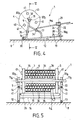
- the unwinder designated 1 as a whole in the Figures, is generally constituted by a self-supporting chassis 7, on which a spool 2 is mounted in a swiveling manner formed by a cylindrical core 3 provided at its ends with two flanges 4, 5 of larger diameter, so as to be able to contain a plurality of superimposed layers of coiled sheath 6 able to unwind under the effect of manual voluntary traction.
- the chassis 7 forms a rigid frame comprising two lateral parts 7a, 7b which are mutually parallel and perpendicular to the ground 8, on which it is intended to rest.
- the lateral parts 7a, 7b of the chassis 7 are constituted by lateral support arms 9, 10 directed upwards, and the free ends 9a and 10a of which are suitable for receiving the ends 11a, 11b of an axis 11 passing right through the coil 2 and emerging from the flanges 4, 5 of the coil 2.
- the lateral parts 7a, 7b also consist of two horizontal beams 12, 13 extending said support arms 9, 10 at their lower part opposite the ends 9a, 10a.
- the connection of said arms and side members is effected by a curvature of an initially straight tube to form an angle ⁇ , such as to give the assembly its stability, when the coil 2 is in place.
- the angle ⁇ chosen is equal to 70 °.
- the parts 7a, 7b thus produced are fixedly joined together by a first spacer 16 arranged between the arms 9 and 10 substantially at their lower part and perpendicularly, and by a second spacer 17 arranged identically between the struts 14 and 15.
- the longitudinal members 12, 13 of the chassis 7 have two free ends 12a, 13a connected together by a vertical facade element 18 constituting a front part of the chassis 7, integral with two telescopic arms 19, 20 capable of sliding in the longitudinal members for adjusting the length of said chassis 7.
- the front element 18 of the chassis 7 comprises, on the one hand, a flexible support forming a clamp 21, into which the free end 6a of the sheath 6 can be clipped in order to maintain it between two samples, or during 'A cutting operation during a sampling and, on the other hand, a transverse roller 22 disposed in the immediate vicinity of the clamp 21 to facilitate unwinding.
- the distance separating the clamp 21 from the coil is such as to give the unwound coil a length sufficient to avoid angular distortions with respect to said coil.
- front element 18 of rectangular conformation is arranged transversely to the side members 12 and 13 of the chassis, and that it can be the subject of an advertising medium 23.
- its lateral uprights 18a and 18b comprise sleeves 24, 25 or 26, 27, arranged in pairs, along the same axis, respectively on said uprights and making it possible to receive, on one side or the other, a foot 28 carrying the clamp 21.
- the front element 18 comprises a handle 29 facilitating the movement of the unwinder 1 before, during or after loading the reel 2.
- the height h2 of the support arms 9, 10, and therefore of the axis 11 passing through the coil is greater than the radius r1 of the coil 2, so that after loading of the latter on the chassis 7, it is no longer in contact with the ground 8 and can rotate freely around its axis 11 as a function of the flexible sheath unwinding needs, effected by traction.
- the loading and unloading of the reel is carried out by tilting the chassis in one direction F1, or in the other direction F2, around a fulcrum A on the ground 8, located in the angle ⁇ formed by the support arms 9, 10 relative to the corresponding side members 12, 13 , then acting like a lever arm.
- the free ends 9a, 10a of the support arms 9, 10 comprise means for gripping the ends 11a, 11b of the axis 11 of the coil 2, which means consist of two open bearings in the manner of a fork 32, 33, so as to allow the reception of the axis 11 by engagement in a direction perpendicular to the latter.
- the gripping forks 32, 33 form asymmetrical branches, of which those 32a, 33a directed towards the outside of the chassis 7 are extended relatively with respect to those 32b, 33b directed towards the inside, so as to constitute sliding ramps of the spindle axis 2 of coil 2, when it is gripped, and during its loading onto the chassis 7.
- two front rollers 34 and rear 35 are arranged transversely, respectively between the front parts of the struts 14 and 15, and between the rear lower parts of the support arms 9 and 10.
- these are arranged near a lower peripheral zone of the coil 2, once in place.
- the front bar 34 constitutes a stop to the unwanted unwinding of the free end 6a of the sheath 6 after removal, the rear bar 35 constituting an additional stop.
- the flexible sheath can be wound on the reel 1 in tight turns but, when its end is relaxed because of its very flexibility, it tends to return to a rectilinear shape or, at least the turns tend to deform, so as to take a configuration in which they have the largest possible diameter, greater than that which they have when they are joined.
- the bars or rollers 34, 35 are approximately symmetrical with respect to the vertical plane passing through the axis of the coil.
- bars or rollers 34, 35, and also 22 located on the front element 18 has the advantage of facilitating the unwinding of the coil 2 during a new withdrawal, by reducing the friction of the sheath. 6.
- the clamp 21 also contributes to preventing the unwanted unwinding of the sheath 6 by pinching its end 6a.
- An additional means is provided for the same purpose and consists in that, on each of the turns formed by the sheath 6 wound in a web on the coil 2, is continuously arranged a film of stretchable plastic material forming a strip 36 of width such as allow it to overlap, and consequently ensure the holding in place of the turns of sheath 6 not unwound remaining in sheet compared to those unwound having resumed their natural slender shape.
- the flanges 4, 5 of the coil 2 comprise at least one stop plate 40 produced on their respective periphery and capable of constituting a means of immobilization in rotation of the reel 2, when it is waiting on the ground, for its gripping by the chassis 7.
- At least one of the flanges 4, 5 of the coil 2 has a plurality of studs 41 arranged in relief on its external face and regularly distributed equidistant from the center O, so as to facilitate, on the one hand, its removal in a stack by the forks of an elevating machine and bring it close to the self-supporting chassis 7 and, on the other hand, to ensure its balance on the ground before being tilted horizontally to be taken by the support arms 9 , 10 of said chassis 7 via the forks 32, 33.
Landscapes
- Unwinding Of Filamentary Materials (AREA)
Applications Claiming Priority (2)
| Application Number | Priority Date | Filing Date | Title |
|---|---|---|---|
| FR9214526A FR2698622B1 (fr) | 1992-12-02 | 1992-12-02 | Dérouleur de gaine flexible. |
| FR9214526 | 1992-12-02 |
Publications (2)
| Publication Number | Publication Date |
|---|---|
| EP0600770A1 true EP0600770A1 (de) | 1994-06-08 |
| EP0600770B1 EP0600770B1 (de) | 1996-07-10 |
Family
ID=9436157
Family Applications (1)
| Application Number | Title | Priority Date | Filing Date |
|---|---|---|---|
| EP19930402861 Expired - Lifetime EP0600770B1 (de) | 1992-12-02 | 1993-11-25 | Abwickelvorrichtung für biegsamen Schlauch |
Country Status (3)
| Country | Link |
|---|---|
| EP (1) | EP0600770B1 (de) |
| DE (1) | DE69303584D1 (de) |
| FR (1) | FR2698622B1 (de) |
Cited By (5)
| Publication number | Priority date | Publication date | Assignee | Title |
|---|---|---|---|---|
| US5566901A (en) * | 1994-12-13 | 1996-10-22 | Wilder; Ray J. | Method and apparatus for winding fire hose |
| AU676988B3 (en) * | 1996-03-15 | 1997-03-27 | David Leo Watkins | Reel supporting apparatus |
| US8403345B2 (en) | 2011-05-13 | 2013-03-26 | Michael Angelo Designs, Llc | Apparatus with wire cart for moving, storing and dispensing spooled material |
| US8616485B2 (en) | 2011-05-13 | 2013-12-31 | Michael Angelo Designs, Llc | Apparatus for moving and dispensing spooled material |
| CN110467068A (zh) * | 2019-08-23 | 2019-11-19 | 国网山东省电力公司枣庄供电公司 | 牵引绳绕线盘放置架 |
Families Citing this family (2)
| Publication number | Priority date | Publication date | Assignee | Title |
|---|---|---|---|---|
| USD829801S1 (en) | 2015-12-14 | 2018-10-02 | Hanwha Techwin Co., Ltd. | Surveillance camera |
| FI130963B1 (fi) * | 2021-11-03 | 2024-06-19 | Ab Finlandia Automation Oy | Kelateline |
Citations (3)
| Publication number | Priority date | Publication date | Assignee | Title |
|---|---|---|---|---|
| US3304060A (en) * | 1965-02-11 | 1967-02-14 | Bea Wanless | Reel lift |
| US4705283A (en) * | 1985-03-15 | 1987-11-10 | Kleisath Stanley N | Electricians wire spool carrier |
| EP0446653A1 (de) * | 1990-03-08 | 1991-09-18 | MIGEN S.r.l. | Vorrichtung zum Handhaben flexibler Elemente |
-
1992
- 1992-12-02 FR FR9214526A patent/FR2698622B1/fr not_active Expired - Fee Related
-
1993
- 1993-11-25 EP EP19930402861 patent/EP0600770B1/de not_active Expired - Lifetime
- 1993-11-25 DE DE69303584T patent/DE69303584D1/de not_active Expired - Lifetime
Patent Citations (3)
| Publication number | Priority date | Publication date | Assignee | Title |
|---|---|---|---|---|
| US3304060A (en) * | 1965-02-11 | 1967-02-14 | Bea Wanless | Reel lift |
| US4705283A (en) * | 1985-03-15 | 1987-11-10 | Kleisath Stanley N | Electricians wire spool carrier |
| EP0446653A1 (de) * | 1990-03-08 | 1991-09-18 | MIGEN S.r.l. | Vorrichtung zum Handhaben flexibler Elemente |
Cited By (5)
| Publication number | Priority date | Publication date | Assignee | Title |
|---|---|---|---|---|
| US5566901A (en) * | 1994-12-13 | 1996-10-22 | Wilder; Ray J. | Method and apparatus for winding fire hose |
| AU676988B3 (en) * | 1996-03-15 | 1997-03-27 | David Leo Watkins | Reel supporting apparatus |
| US8403345B2 (en) | 2011-05-13 | 2013-03-26 | Michael Angelo Designs, Llc | Apparatus with wire cart for moving, storing and dispensing spooled material |
| US8616485B2 (en) | 2011-05-13 | 2013-12-31 | Michael Angelo Designs, Llc | Apparatus for moving and dispensing spooled material |
| CN110467068A (zh) * | 2019-08-23 | 2019-11-19 | 国网山东省电力公司枣庄供电公司 | 牵引绳绕线盘放置架 |
Also Published As
| Publication number | Publication date |
|---|---|
| DE69303584D1 (de) | 1996-08-14 |
| FR2698622B1 (fr) | 1995-02-17 |
| FR2698622A1 (fr) | 1994-06-03 |
| EP0600770B1 (de) | 1996-07-10 |
Similar Documents
| Publication | Publication Date | Title |
|---|---|---|
| US5988555A (en) | Cable winding machine | |
| EP2957487B1 (de) | Instandsetzungsvorrichtung für eine fahrzeug-laufkette, vorrichtung und verfahren zum wechseln der ketten-laufflächen mithilfe dieser instandsetzungsvorrichtung | |
| EP0721905A1 (de) | Verfahren und Vorrichtung zum Vorbereiten des Öffnens eines Bahnwickels | |
| EP0600770B1 (de) | Abwickelvorrichtung für biegsamen Schlauch | |
| EP1688369A1 (de) | Schachtel und Verfahren zum Versenden von Kabelaufnahmespule | |
| FR2985710A1 (fr) | Chariot de manutention pour transporter des tourets de cables | |
| FR2658156A1 (fr) | Procede d'emballage, emballage et dispositif de manutention des produits en bandes. | |
| FR3012403A1 (fr) | Dispositif de chariot a tablier tournant. | |
| EP3215692B1 (de) | Rollwagen für einen teleskopmast einer plattenhebevorrichtung, mit diesem wagen ausgestattete vorrichtung und implementierungsverfahren | |
| EP0420721A1 (de) | Verfahren zur Doppelaufwicklung eines Kabels oder dergleichen auf der Aussenfläche einer Trommel | |
| FR3002217A1 (fr) | Dispositif pour enrouler / derouler un objet allonge | |
| EP1757551B1 (de) | Vorrichtung zum Abwickeln von Rollen aus halbstarrem Schlauch oder Kabel | |
| FR2819241A1 (fr) | Appareil pour la distribution de produits souples a partir d'une couronne | |
| FR2884653A1 (fr) | Procede, et dispositif portatif, pour le pre-filage d'une gaine. | |
| FR2825993A1 (fr) | Support-devidoir de touret equipe d'un systeme de levage | |
| EP0759004B1 (de) | Verfahren und vorrichtung zum wickelförmigen speichern von kabeln oder dergleichen | |
| FR2636055A1 (fr) | Derouleur pour tube plastique semi-rigide | |
| WO2009132654A1 (en) | A cable reel assembly, and a cable reel support | |
| FR2703985A1 (fr) | Dérouleur pour gaines métalliques notamment de gros diamètre. | |
| FR2707221A1 (fr) | Véhicule de transport d'au moins une bobine. | |
| BE1010523A3 (fr) | Ensemble pour le stockage et le debit d'un element allonge, par exemple un tuyau flexible pour le tubage de cheminees. | |
| FR3067339A1 (fr) | Devidoir multiple | |
| FR2741611A1 (fr) | Devidoir a bobine extractible pour la vente au metre d'un produit souple notamment filiforme ou tubulaire | |
| FR3013799A1 (fr) | Dispositif de recouvrement par un isolant de troncon de gaine de circuit de soufflerie et ventilation. | |
| LU83198A1 (fr) | Perfectionnements aux appareils de distribution de produits en rouleaux notamment d'essuie mains en papier |
Legal Events
| Date | Code | Title | Description |
|---|---|---|---|
| PUAI | Public reference made under article 153(3) epc to a published international application that has entered the european phase |
Free format text: ORIGINAL CODE: 0009012 |
|
| AK | Designated contracting states |
Kind code of ref document: A1 Designated state(s): BE DE ES FR GB IT NL |
|
| 17P | Request for examination filed |
Effective date: 19940722 |
|
| 17Q | First examination report despatched |
Effective date: 19951004 |
|
| GRAH | Despatch of communication of intention to grant a patent |
Free format text: ORIGINAL CODE: EPIDOS IGRA |
|
| GRAA | (expected) grant |
Free format text: ORIGINAL CODE: 0009210 |
|
| AK | Designated contracting states |
Kind code of ref document: B1 Designated state(s): BE DE ES FR GB IT NL |
|
| PG25 | Lapsed in a contracting state [announced via postgrant information from national office to epo] |
Ref country code: NL Free format text: LAPSE BECAUSE OF FAILURE TO SUBMIT A TRANSLATION OF THE DESCRIPTION OR TO PAY THE FEE WITHIN THE PRESCRIBED TIME-LIMIT Effective date: 19960710 Ref country code: IT Free format text: LAPSE BECAUSE OF FAILURE TO SUBMIT A TRANSLATION OF THE DESCRIPTION OR TO PAY THE FEE WITHIN THE PRESCRIBED TIME-LIMIT;WARNING: LAPSES OF ITALIAN PATENTS WITH EFFECTIVE DATE BEFORE 2007 MAY HAVE OCCURRED AT ANY TIME BEFORE 2007. THE CORRECT EFFECTIVE DATE MAY BE DIFFERENT FROM THE ONE RECORDED. Effective date: 19960710 Ref country code: GB Effective date: 19960710 Ref country code: ES Free format text: THE PATENT HAS BEEN ANNULLED BY A DECISION OF A NATIONAL AUTHORITY Effective date: 19960710 |
|
| GRAH | Despatch of communication of intention to grant a patent |
Free format text: ORIGINAL CODE: EPIDOS IGRA |
|
| REF | Corresponds to: |
Ref document number: 69303584 Country of ref document: DE Date of ref document: 19960814 |
|
| PG25 | Lapsed in a contracting state [announced via postgrant information from national office to epo] |
Ref country code: DE Effective date: 19961011 |
|
| PG25 | Lapsed in a contracting state [announced via postgrant information from national office to epo] |
Ref country code: BE Effective date: 19961130 |
|
| NLV1 | Nl: lapsed or annulled due to failure to fulfill the requirements of art. 29p and 29m of the patents act | ||
| GBV | Gb: ep patent (uk) treated as always having been void in accordance with gb section 77(7)/1977 [no translation filed] |
Effective date: 19960710 |
|
| PLBE | No opposition filed within time limit |
Free format text: ORIGINAL CODE: 0009261 |
|
| STAA | Information on the status of an ep patent application or granted ep patent |
Free format text: STATUS: NO OPPOSITION FILED WITHIN TIME LIMIT |
|
| BERE | Be: lapsed |
Owner name: ETS POUJOULAT Effective date: 19961130 |
|
| 26N | No opposition filed | ||
| PGFP | Annual fee paid to national office [announced via postgrant information from national office to epo] |
Ref country code: FR Payment date: 20100915 Year of fee payment: 18 |
|
| REG | Reference to a national code |
Ref country code: FR Ref legal event code: ST Effective date: 20120731 |
|
| PG25 | Lapsed in a contracting state [announced via postgrant information from national office to epo] |
Ref country code: FR Free format text: LAPSE BECAUSE OF NON-PAYMENT OF DUE FEES Effective date: 20111130 |