EP0601098B1 - Druckregeleinheit zur versorgung eines druckfluids aus ausweichzufuhrleitungen - Google Patents
Druckregeleinheit zur versorgung eines druckfluids aus ausweichzufuhrleitungen Download PDFInfo
- Publication number
- EP0601098B1 EP0601098B1 EP92919383A EP92919383A EP0601098B1 EP 0601098 B1 EP0601098 B1 EP 0601098B1 EP 92919383 A EP92919383 A EP 92919383A EP 92919383 A EP92919383 A EP 92919383A EP 0601098 B1 EP0601098 B1 EP 0601098B1
- Authority
- EP
- European Patent Office
- Prior art keywords
- pressure
- outlet
- line
- preferential
- chamber
- Prior art date
- Legal status (The legal status is an assumption and is not a legal conclusion. Google has not performed a legal analysis and makes no representation as to the accuracy of the status listed.)
- Expired - Lifetime
Links
Images

Classifications
-
- B—PERFORMING OPERATIONS; TRANSPORTING
- B60—VEHICLES IN GENERAL
- B60T—VEHICLE BRAKE CONTROL SYSTEMS OR PARTS THEREOF; BRAKE CONTROL SYSTEMS OR PARTS THEREOF, IN GENERAL; ARRANGEMENT OF BRAKING ELEMENTS ON VEHICLES IN GENERAL; PORTABLE DEVICES FOR PREVENTING UNWANTED MOVEMENT OF VEHICLES; VEHICLE MODIFICATIONS TO FACILITATE COOLING OF BRAKES
- B60T17/00—Component parts, details, or accessories of power brake systems not covered by groups B60T8/00, B60T13/00 or B60T15/00, or presenting other characteristic features
- B60T17/02—Arrangements of pumps or compressors, or control devices therefor
-
- A—HUMAN NECESSITIES
- A62—LIFE-SAVING; FIRE-FIGHTING
- A62B—DEVICES, APPARATUS OR METHODS FOR LIFE-SAVING
- A62B9/00—Component parts for respiratory or breathing apparatus
- A62B9/02—Valves
-
- Y—GENERAL TAGGING OF NEW TECHNOLOGICAL DEVELOPMENTS; GENERAL TAGGING OF CROSS-SECTIONAL TECHNOLOGIES SPANNING OVER SEVERAL SECTIONS OF THE IPC; TECHNICAL SUBJECTS COVERED BY FORMER USPC CROSS-REFERENCE ART COLLECTIONS [XRACs] AND DIGESTS
- Y10—TECHNICAL SUBJECTS COVERED BY FORMER USPC
- Y10T—TECHNICAL SUBJECTS COVERED BY FORMER US CLASSIFICATION
- Y10T137/00—Fluid handling
- Y10T137/2496—Self-proportioning or correlating systems
- Y10T137/2559—Self-controlled branched flow systems
- Y10T137/2564—Plural inflows
- Y10T137/2567—Alternate or successive inflows
- Y10T137/2569—Control by depletion of source
Definitions
- the invention relates to a pressure regulating unit for supplying a pressure fluid, especially breathing gas, to a user from a preferential supply line or from an alternative line, and comprising a switching means including a valve means arranged to connect either of the two supply lines to a common outlet of the unit in dependence on the pressure in the preferential supply line, and a pressure regulator for controlling the fluid flow to said outlet so as to maintain the fluid pressure at the outlet stable at a desired level.
- Such a device is intended for use in situations wherein it is necessary to maintain a stable outlet pressure from the unit even if the supply through the preferential supply line disappears for shorter periods.
- a topical example is in connection with the breathing gas supply to a combat plane pilot.
- the pressure energy from the compressor of the airplane is used to drive the plane and the equipment thereof, so that one does not have the necessary pressure for air supply to the pilot.
- the combat plane pilots therefore have an alternative breathing gas source, consisting of liquid pressurized oxygen, which is connected to an alternative supply line.
- This alternative source constitutes an emergency reservoir which - mainly because of space limitations - has a relatively small capacity. It is therefore essential that this emergency reservoir is used as little as possible.
- a pressure regulating unit wherein a switching means controls gas supply from a pair of supply lines to a common outlet.
- the supply lines are connected through respective pressure regulators to separate high pressure sources of which each consists of a battery of high pressure gas bottles.
- the unit is designed for automatically and without any discontinuity to ensure the supply from the two supply lines to the common outlet in a predetermined order, the stand-by line being placed in communication with the outlet only when the pressure in the supply line being drained has dropped below a predetermined critical value.
- the switching means comprises a valve housing having a pair of interconnected spring-influenced diaphragms which cooperate with respective valve seats on opposite sides of the valve housing, and which define respective chambers communicating with a respective high pressure source.
- a spring-controlling means for influencing the springs so that one spring applies a greater thrust than the other, so that a greater thrust is applied to the diaphragm assembly alternately in one direction and the other.
- one supply line may have priority over the other, so that the preferential line is maintained connected until the pressure drops below the critical value. At that time this line is disconnected, whereas the other line then i completely connected and takes over the gas supply. Thereafter the spring-force controlling means is switched over, so that the now connected second line takes priority while its high pressure source is drained until the pressure thereof has dropped to the critical value.
- This device makes it possible to replace a drained gas bottle battery with a fresh battery without the gas supply being disturbed, and without any switching of the pressure regulator of the unit being required.
- the device is intended for alternating draining of high pressure sources until the pressure of the utilized source has dropped to a certain value, and thus is not suitable for the application stated in the introduction.
- EP-A-0 125 447 discloses a selector valve for an aircraft on board oxygen generation system. This valve does, however, not disclose a pressure regulator, but instead a shuttle valve, which is responsive to the gas pressures of a secondary source.
- a pressure regulating unit of the introductorily stated type which according to the invention, is characterized in that the switching means comprises a first chamber connected through a channel to the preferential supply line and containing a spring-actuated first sensing diaphragm sensing the pressure in the preferential supply line and being operatively connected to and driving said valve means, the valve means comprising first and second valves arranged to connect the preferential line to an outlet chamber and keep the alternative line shut off as long as the pressure in the preferential line is above said desired pressure level, and further to connect the alternative line to said outlet chamber and keep the preferential line shut off when the pressure therein drops below said level, and that the regulator comprises a second chamber connected through a passage to said outlet of the unit and containing a spring-actuated second sensing diaphragm sending the fluid pressure at said outlet and being operatively connected to a regulator element controlling the fluid flow from said outlet chamber to said outlet, so that said fluid pressure is maintained at said desired level.
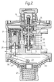
- the device shown in the drawing constitutes an integrated pressure regulator and switching means, wherein the switching means essentially comprises a valve housing 1 (with an associated valve structure) and a first diaphragm housing 2 in association therewith, and the regulator comprises a regulator element 3 in association with a second diaphragm housing 4. As shown, the two diaphragm housings 2, 4 are disposed at opposite sides of the valve housing 1, this giving a compact and simple construction of the unit in association with the remaining components.
- the valve housing 1 has a first inlet 5 to which a first, preferential supply line 6 is connected, and a second inlet 7 to which a second, alternative supply line 8 is connected.
- the two inlets 5, 7 are connected through respective valves 9, 10 (to be further described later) to a common valve or outlet chamber 11 which is connected through the regulator to a common outlet 12 from the unit.
- the first diaphragm housing 2 defines a first chamber 13 in which a first sensing diaphragm 14 is mounted in the shown manner, the diaphragm being clamped at its periphery and in its central area being actuated by a force-exerting means in the form of a spring 15 pressing the diaphragm 14 with an adjustable force in the direction towards the chamber 13.
- a force-exerting means in the form of a spring 15 pressing the diaphragm 14 with an adjustable force in the direction towards the chamber 13.
- a channel 16 (only suggested with dashed lines) the chamber 13 is in open connection with the inlet 5 from the preferential supply line 6, so that the diaphragm 14 at any time senses and is influenced by the pressure in this line.
- the diaphragm 14 in its central area is connected to an operating rod 17 which is displaceably arranged in the valve housing 1 and on which there is mounted a first and a second valve body 18 and 19, respectively, forming part of a respective one of the two aforementioned valves 9 and 10 controlling the connection between the respective supply lines 6, 8 and the common outlet chamber 11.
- the valve body 18 is displaceable on the operating rod 17 and is force-influenced in the direction towards the associated valve seat by means of a spring 20, so that the valve 9 is a one-way valve.
- the valve body 19 is fixedly mounted on the rod 17 at a suitable position for closing the valve 9 when the valve 10 is opened with displacement of the rod when the pressure in the preferential supply line 6 drops below a certain value.
- the regulator element 3 in the illustrated embodiment is in the form of a spring-loaded piston which is slidable in a cylinder guide 21 which is shown to be placed in a part of the valve housing 1.
- the piston 3 is operatively connected to a second sensing diaphragm 22 which is mounted in the shown manner in a second chamber 23 which is defined by the second diaphragm housing 4 and through a passage 24 is in open connection with the outlet 12 of the unit.
- the second sensing diaphragm 22 is clamped at its periphery, and in its central area it is influenced by a spring 25 which, with an adjustable force, actuates the diaphragm in the direction towards the chamber 23.
- the piston 3 is connected to the central area of the diaphragm 22 through a connecting rod 26 extending through the passage 24, and a lever 27.
- a flow passage 28 which is defined by one end of the piston 3 facing the diaphragm 22, and an annular seat 29.
- the size of this passage is controlled by the piston 3 in cooperation with the sensing diaphragm 22. Since the chamber 23 is in open connection with the outlet 12, varying pressure at the outlet, and consequently in the chamber 23, will result in that the piston controls the flow passage 28 correspondingly, so that a stable outlet pressure is maintained, the spring force on the diaphragm 22 being adapted for this purpose.
- Fig. 2 shows the situation with supply through the alternative supply line 28.
- the pressure at the inlet 5, and consequently in the chamber 13, is too low to balance the force from the spring 15.
- the sensing diaphragm 14 and the operating rod 17 then are pressed downwards, and the valve body 19 opens the passage between the alternative line 8 and the chamber 11.
- the pressure in the chamber 11 consequently becomes higher than at the inlet 5 of the preferential line, and the one-way valve 9 is kept closed.
- the sensing diaphragm 14 is pressed upwards, so that the valve body 19 again closes the passage between the alternative line 8 and the outlet chamber 11. The situation is then again as shown in Fig. 1.
Landscapes
- Health & Medical Sciences (AREA)
- Pulmonology (AREA)
- Engineering & Computer Science (AREA)
- General Health & Medical Sciences (AREA)
- Business, Economics & Management (AREA)
- Emergency Management (AREA)
- Transportation (AREA)
- Mechanical Engineering (AREA)
- Control Of Fluid Pressure (AREA)
- Valves And Accessory Devices For Braking Systems (AREA)
- Vehicle Body Suspensions (AREA)
- Electrical Discharge Machining, Electrochemical Machining, And Combined Machining (AREA)
Claims (5)
- Eine Druckregeleinheit zur Versorgung mit einem unter Druck stehenden Fluid, insbesondere Atemluft, aus einer bevorzugten oder einer alternativen Versorgungsleitung zu einem Benutzer, bestehend auseiner Umschaltvorrichtung (1, 9, 10, 13-20) einschließlich einer Ventileinrichtung (9, 10, 17-20) zur Verbindung jeweils einer der beiden Versorgungsleitungen (6, 8) mit einem gemeinsamen Auslaß (12) der Einheit in Abhängigkeit vom in der bevorzugten Leitung herrschenden Druck undeinem Druckregler (3, 22-29) zur Regelung der Fluidströmung zu dem genannten Auslaß und somit zur Stabilisierung des Fluiddrucks am Auslaß auf der gewünschten Höhe,
DADURCH GEKENNZEICHNET,daß die Umschaltvorrichtung (1, 9, 13-20) aus einer mit der bevorzugten Versorgungsleitung (6) über einen Kanal (16) verbundenen, eine federbetätigte, mit der vorgenannten Ventileinrichtung (9, 10, 17-20) mechanisch verbundene und diese betätigende erste Fühlermembran (14) zur Messung des Drucks in der bevorzugten Versorgungsleitung (6) enthaltenden ersten Kammer (13) besteht, die Ventilvorrichtung aus einem ersten und einem zweiten Ventil (9, 10) zur Verbindung der bevorzugten Versorgungsleitung (6) mit einer Auslaßkammer (11) und Absperrung der alternativen Leitung (8), solange der Druck in der bevorzugten Leitung (6) oberhalb des gewünschten Druckwertes liegt, und außerdem zur Verbindung der alternativen Leitung (8) mit der vorgenannten Auslaßkammer (11) und Absperrung der bevorzugten Leitung (6), sobald der Druck hierin unter den vorgenannten Wert fällt, besteht unddaß der Regler (3, 22-29) eine zweite Kammer (23) beinhaltet, die durch eine Durchflußöffnung (24) mit dem vorgenannten Auslaß (12) der Einheit verbunden ist und eine federbetätigte zweite Fühlermembran (22) enthält, die den Fluiddruck am vorgenannten Auslaß (12) mißt und mit einem die Fluidströmung von der vorgenannten Auslaßkammer (11) zum vorgenannten Auslaß (12) steuernden Regelelement (3) mechanisch verbunden ist, wodurch der vorgenannte Fluiddruck auf dem vorgenannten gewünschten Wert gehalten wird. - Eine Druekregeleinheit gemäß Anspruch 1, DADURCH GEKENNZEICHNET, daß die mechanische Verbindung zwischen der ersten Fühlermembran (14) und dem ersten und dem zweiten Ventil (9, 10) aus einer mit dem mittleren Bereich der Membran (14) verbundenen Betätigungsstange (17) besteht, auf der die Ventilkörper (18 bzw. 19) der Ventile angebracht sind, wobei die Ventilkörper die Verbindung zwischen der jeweiligen Versorgungsleitung (6, 8) und der vorgenannten Auslaßkammer (11) steuern.
- Eine Druckregeleinheit gemäß Anspruch 1, DADURCH GEKENNZEICHNET, daß das Ventil (9) zwischen der bevorzugten Versorgungsleitung (6) und der Auslaßkammer (11) ein Richtungsventil ist.
- Eine Druckregeleinheit gemäß einem oder mehreren der Ansprüche 1 bis 3, DADURCH GEKENNZEICHNET, daß die Ventile (9, 10) und das Regelelement (3) in einem gemeinsamen Gehäuse (1) und die erste und zweite Kammer (13 bzw. 23) an gegenüberliegenden Seiten des Gehäuses (1) angeordnet sind.
- Eine Druckregeleinheit gemäß einem oder mehreren der vorgenannten Ansprüche, DADURCH GEKENNZEICHNET, daß das Regelelement (3) ein federbelasteter, in einer zylindrischen Führung (20) gleitender Kolben (3) ist, der über eine Hebelvorrichtung (26, 27) mit der zweiten Fühlermembran (22) verbunden ist, und daß eine Durchflußöffnung (28) zwischen der Auslaßkammer (11) und dem Auslaß (12) der Einheit aus einem der vorgenannten Membran (22) zugewandten Ende des Kolbens (3) und einem ringförmigen Sitz (29) für das vorgenannte Kolbenende gebildet wird.
Applications Claiming Priority (3)
| Application Number | Priority Date | Filing Date | Title |
|---|---|---|---|
| NO913393A NO176078C (no) | 1991-08-29 | 1991-08-29 | Trykkreguleringsenhet for tilförsel av et trykkfluidum fra alternative tilförselslinjer |
| NO913393 | 1991-08-29 | ||
| PCT/NO1992/000136 WO1993004737A1 (en) | 1991-08-29 | 1992-08-28 | A pressure regulating unit for supplying a pressurized fluid from alternative supply lines |
Publications (2)
| Publication Number | Publication Date |
|---|---|
| EP0601098A1 EP0601098A1 (de) | 1994-06-15 |
| EP0601098B1 true EP0601098B1 (de) | 1997-01-22 |
Family
ID=19894411
Family Applications (1)
| Application Number | Title | Priority Date | Filing Date |
|---|---|---|---|
| EP92919383A Expired - Lifetime EP0601098B1 (de) | 1991-08-29 | 1992-08-28 | Druckregeleinheit zur versorgung eines druckfluids aus ausweichzufuhrleitungen |
Country Status (6)
| Country | Link |
|---|---|
| US (1) | US5542417A (de) |
| EP (1) | EP0601098B1 (de) |
| AU (1) | AU2564892A (de) |
| DE (1) | DE69217066D1 (de) |
| NO (1) | NO176078C (de) |
| WO (1) | WO1993004737A1 (de) |
Families Citing this family (8)
| Publication number | Priority date | Publication date | Assignee | Title |
|---|---|---|---|---|
| NO311186B1 (no) | 1999-12-13 | 2001-10-22 | Techwood As | Ventilanordning for styrt tilförsel av et trykkfluid |
| NO996196D0 (de) * | 1999-12-14 | 1999-12-14 | Aker Eng As | |
| NO313601B1 (no) * | 2000-01-06 | 2002-10-28 | Ottestad Breathing Syst As | Trykkreguleringsventil for styring av oppstroms fluidtrykk |
| US6484720B1 (en) * | 2000-10-20 | 2002-11-26 | Applied Marketing, Inc. | Five spring regulator |
| KR100906434B1 (ko) * | 2005-03-10 | 2009-07-09 | 가부시키가이샤 다이요 | 변환밸브장치 및 유체압 실린더장치 |
| KR101399370B1 (ko) * | 2013-08-28 | 2014-05-27 | 주식회사 산청 | 호흡보호용 공기공급장치의 압력조절기 |
| KR101440426B1 (ko) * | 2013-08-28 | 2014-09-17 | 주식회사 산청 | 조립이 용이한 호흡보호용 공기공급장치의 압력조절기 |
| KR101399371B1 (ko) * | 2013-08-28 | 2014-05-27 | 주식회사 산청 | 감압조절이 용이한 호흡보호용 공기공급장치의 압력조절기 |
Family Cites Families (8)
| Publication number | Priority date | Publication date | Assignee | Title |
|---|---|---|---|---|
| US2775980A (en) * | 1957-01-01 | renaudie | ||
| US2354286A (en) * | 1942-09-14 | 1944-07-25 | Phillips Petroleum Co | Automatic change-over device |
| DE1099294B (de) * | 1958-01-09 | 1961-02-09 | Knapsack Ag | Selbsttaetige Umschaltvorrichtung fuer fluessige und gasfoermige Medien |
| US4354518A (en) * | 1980-09-08 | 1982-10-19 | Nippon Air Brake Co., Ltd. | Diaphragm piston operated valve device |
| US4499914A (en) * | 1983-04-14 | 1985-02-19 | Litton Systems, Inc. | Selector valve for an aircraft on board oxygen generation system with high pressure oxygen backup |
| GB2184204A (en) * | 1985-11-06 | 1987-06-17 | Mara Engineering Limited | Valve system |
| US4674526A (en) * | 1986-09-12 | 1987-06-23 | Bellofram Corporation | Switching valve |
| US5183072A (en) * | 1991-10-21 | 1993-02-02 | Matheson Gas Products, Inc. | Automatic switchover valve |
-
1991
- 1991-08-29 NO NO913393A patent/NO176078C/no not_active IP Right Cessation
-
1992
- 1992-08-28 DE DE69217066T patent/DE69217066D1/de not_active Expired - Lifetime
- 1992-08-28 AU AU25648/92A patent/AU2564892A/en not_active Abandoned
- 1992-08-28 US US08/199,160 patent/US5542417A/en not_active Expired - Fee Related
- 1992-08-28 EP EP92919383A patent/EP0601098B1/de not_active Expired - Lifetime
- 1992-08-28 WO PCT/NO1992/000136 patent/WO1993004737A1/en not_active Ceased
Also Published As
| Publication number | Publication date |
|---|---|
| WO1993004737A1 (en) | 1993-03-18 |
| AU2564892A (en) | 1993-04-05 |
| NO176078B (no) | 1994-10-17 |
| EP0601098A1 (de) | 1994-06-15 |
| NO913393L (no) | 1993-03-01 |
| DE69217066D1 (de) | 1997-03-06 |
| NO176078C (no) | 1995-01-25 |
| US5542417A (en) | 1996-08-06 |
| NO913393D0 (no) | 1991-08-29 |
Similar Documents
| Publication | Publication Date | Title |
|---|---|---|
| USRE36223E (en) | First stage scuba regulator | |
| EP1295189B1 (de) | Vorrichtung zum regeln eines gasdurchflusses | |
| US4226257A (en) | Scuba regulator | |
| US4173986A (en) | Pressurized gas flow control valve and assembly thereof with reducer regulator | |
| EP0817990B1 (de) | Gas druck-regler | |
| WO1995021650A1 (en) | G-force and altitude responsive oxygen breathing controller | |
| KR970705781A (ko) | 개량된 2단계 압력 조절기(improved two-stage pressure regulator) | |
| US5348001A (en) | Oxygen breathing controls | |
| JPH0436918B2 (de) | ||
| US5542417A (en) | Pressure regulating unit for supplying a pressurized fluid from alternative supply lines | |
| US2637946A (en) | Fluid pressure regulator | |
| US5056550A (en) | Pilot regulator for valves | |
| US6095184A (en) | Pressure regulator with integrated control valve, adjustable downstream pressure build and quick exhaust | |
| US3260278A (en) | Regulating valve having removable valve unit | |
| US4378816A (en) | Hydraulic priority valve | |
| US2952264A (en) | Regulator for pressurizing device | |
| US2892456A (en) | Pressure demand breathing oxygen mask with built-in regulator | |
| EP0078644A2 (de) | Atemluft-Zufuhrregler | |
| US4513775A (en) | Pressure regulator | |
| US3195317A (en) | Flow control apparatus | |
| US3219052A (en) | Back pressure regulator valve assembly | |
| JPS62116392A (ja) | 調整弁及びそれを備えた複動弁装置 | |
| GB2284687A (en) | Fluid pressure regulator | |
| US2987073A (en) | Fluid pressure relief valve | |
| US3722534A (en) | Flow control valve system with rapid closing valve |
Legal Events
| Date | Code | Title | Description |
|---|---|---|---|
| PUAI | Public reference made under article 153(3) epc to a published international application that has entered the european phase |
Free format text: ORIGINAL CODE: 0009012 |
|
| 17P | Request for examination filed |
Effective date: 19940322 |
|
| AK | Designated contracting states |
Kind code of ref document: A1 Designated state(s): DE DK ES FR GB IT SE |
|
| 17Q | First examination report despatched |
Effective date: 19950718 |
|
| GRAG | Despatch of communication of intention to grant |
Free format text: ORIGINAL CODE: EPIDOS AGRA |
|
| GRAH | Despatch of communication of intention to grant a patent |
Free format text: ORIGINAL CODE: EPIDOS IGRA |
|
| GRAH | Despatch of communication of intention to grant a patent |
Free format text: ORIGINAL CODE: EPIDOS IGRA |
|
| GRAA | (expected) grant |
Free format text: ORIGINAL CODE: 0009210 |
|
| AK | Designated contracting states |
Kind code of ref document: B1 Designated state(s): DE DK ES FR GB IT SE |
|
| PG25 | Lapsed in a contracting state [announced via postgrant information from national office to epo] |
Ref country code: IT Free format text: LAPSE BECAUSE OF FAILURE TO SUBMIT A TRANSLATION OF THE DESCRIPTION OR TO PAY THE FEE WITHIN THE PRE;WARNING: LAPSES OF ITALIAN PATENTS WITH EFFECTIVE DATE BEFORE 2007 MAY HAVE OCCURRED AT ANY TIME BEFORE 2007. THE CORRECT EFFECTIVE DATE MAY BE DIFFERENT FROM THE ONE RECORDED.SCRIBED TIME-LIMIT Effective date: 19970122 Ref country code: ES Free format text: THE PATENT HAS BEEN ANNULLED BY A DECISION OF A NATIONAL AUTHORITY Effective date: 19970122 Ref country code: DK Effective date: 19970122 |
|
| REF | Corresponds to: |
Ref document number: 69217066 Country of ref document: DE Date of ref document: 19970306 |
|
| PG25 | Lapsed in a contracting state [announced via postgrant information from national office to epo] |
Ref country code: SE Effective date: 19970422 |
|
| PG25 | Lapsed in a contracting state [announced via postgrant information from national office to epo] |
Ref country code: DE Effective date: 19970423 |
|
| ET | Fr: translation filed | ||
| PLBE | No opposition filed within time limit |
Free format text: ORIGINAL CODE: 0009261 |
|
| 26N | No opposition filed | ||
| PGFP | Annual fee paid to national office [announced via postgrant information from national office to epo] |
Ref country code: GB Payment date: 20000807 Year of fee payment: 9 |
|
| PGFP | Annual fee paid to national office [announced via postgrant information from national office to epo] |
Ref country code: FR Payment date: 20010731 Year of fee payment: 10 |
|
| PG25 | Lapsed in a contracting state [announced via postgrant information from national office to epo] |
Ref country code: GB Free format text: LAPSE BECAUSE OF NON-PAYMENT OF DUE FEES Effective date: 20010828 |
|
| GBPC | Gb: european patent ceased through non-payment of renewal fee |
Effective date: 20010828 |
|
| PG25 | Lapsed in a contracting state [announced via postgrant information from national office to epo] |
Ref country code: FR Free format text: LAPSE BECAUSE OF NON-PAYMENT OF DUE FEES Effective date: 20030430 |
|
| REG | Reference to a national code |
Ref country code: FR Ref legal event code: ST |