EP0601176B1 - Vorrichtung zur höhenanpassung einer laderampe mit verbesserter automatischer schranke für materialbearbeitende fahrzeuge - Google Patents
Vorrichtung zur höhenanpassung einer laderampe mit verbesserter automatischer schranke für materialbearbeitende fahrzeuge Download PDFInfo
- Publication number
- EP0601176B1 EP0601176B1 EP93916431A EP93916431A EP0601176B1 EP 0601176 B1 EP0601176 B1 EP 0601176B1 EP 93916431 A EP93916431 A EP 93916431A EP 93916431 A EP93916431 A EP 93916431A EP 0601176 B1 EP0601176 B1 EP 0601176B1
- Authority
- EP
- European Patent Office
- Prior art keywords
- ramp
- barrier member
- lip
- lip extension
- dock
- Prior art date
- Legal status (The legal status is an assumption and is not a legal conclusion. Google has not performed a legal analysis and makes no representation as to the accuracy of the status listed.)
- Expired - Lifetime
Links
- 230000004888 barrier function Effects 0.000 title claims abstract description 98
- 230000000977 initiatory effect Effects 0.000 claims description 4
- 230000002093 peripheral effect Effects 0.000 description 4
- 230000000712 assembly Effects 0.000 description 3
- 238000000429 assembly Methods 0.000 description 3
- 230000000903 blocking effect Effects 0.000 description 3
- 238000010276 construction Methods 0.000 description 3
- 230000000284 resting effect Effects 0.000 description 1
Images


Classifications
-
- B—PERFORMING OPERATIONS; TRANSPORTING
- B65—CONVEYING; PACKING; STORING; HANDLING THIN OR FILAMENTARY MATERIAL
- B65G—TRANSPORT OR STORAGE DEVICES, e.g. CONVEYORS FOR LOADING OR TIPPING, SHOP CONVEYOR SYSTEMS OR PNEUMATIC TUBE CONVEYORS
- B65G69/00—Auxiliary measures taken, or devices used, in connection with loading or unloading
- B65G69/28—Loading ramps; Loading docks
- B65G69/2805—Loading ramps; Loading docks permanently installed on the dock
- B65G69/2811—Loading ramps; Loading docks permanently installed on the dock pivoting ramps
- B65G69/2817—Loading ramps; Loading docks permanently installed on the dock pivoting ramps with fluid-operated means
- B65G69/2823—Loading ramps; Loading docks permanently installed on the dock pivoting ramps with fluid-operated means extensible by pivoting parts
Definitions
- the invention relates to a loading dock leveler assembly provided with an adjustable safety barrier for preventing accidental movement of material handling equipment off the loading dock platform when the leveler assembly is in a stored position.
- Loading dock leveler assemblies normally embody a hingedly mounted loading ramp or deck which is adjustable between a stored position wherein an exposed surface thereof is substantially coplanar with the dock platform surface and an operative position allowing loading or unloading of the bed of a truck parked adjacent the front wall of the dock.
- An extension plate or lip is pivotally mounted on the front edge of the ramp and, when in an extended or cantilevered mode, bridges the gap which occurs between the rear end of the truck bed and the front wall of the loading dock.
- dock levelers that include various forms of barriers which physically obstruct and thereby prevent movement of material handling vehicles beyond the front edge of the dock leveler.
- the pivot axis of the lip is set back a substantial distance from the rear edge of the lip so that the rear section of the lip between the pivotal axis and the lip rear edge projects above the ramp surface and forms a barrier when the lip is in a depending position with respect to the ramp.
- This lip integrally includes a barrier unit, a portion of which automatically projects above the ramp exposed surface to form a vehicle barrier of optimum height when the extension plate or lip is in the stored vertical position, and which, when the lip is in the outwardly extending cantilevered operative position, automatically retracts below the exposed ramp surface.
- a dock leveler assembly for a loading dock comprising a pivotally mounted ramp adjustable between a first position wherein an exposed surface of said ramp is substantially coplanar with a platform surface of the dock and a second position for loading and unloading the bed of a vehicle parked at the dock, a barrier member pivotally connected about an axis to a front edge portion of said ramp for selected solely pivotal movement about the axis between an operative position wherein a substantial portion of said barrier member angularly protrudes above the ramp exposed surface, and an inoperative position, wherein no substantial portion of said barrier member angularly protrudes above the ramp exposed surface, a lip extension connected to said barrier member for pivotal movement between a first position wherein said lip extension depends and a second position wherein said lip extension is cantilevered and an actuator for moving the lip extension between said first and second positions, characterized in that said lip extension depends from the ramp front edge portion in said first position and, in said second position, is cantilevered
- a dock leveler assembly for a loading dock comprising a support frame mountable within a pit formed in the platform surface of the dock, a ramp pivotally connected to said support frame and adjustable between a stored position wherein an exposed surface of said ramp is substantially coplanar with the dock platform surface circumjacent the pit, and a non-stored position, a header section affixed to and depending from a front edge portion of said ramp, a barrier member pivotally connected about an axis to said header section for selected solely pivotal movement about the axis between an operative position wherein at least a substantial portion of said barrier member protrudes angularly above the ramp exposed surface and an inoperative position wherein said barrier member does not angularly protrude substantially above the ramp exposed surface, a lip extension connected to said barrier member for pivotal movement between a first position wherein said lip extension depends and a second position wherein said lip extension assumes a cantilevered position and an actuator for moving the lip extension between said first and second
- an improved loading dock leveler having both a pivoting lip and a pivoting safety barrier member mounted on the front edge of the ramp.
- the pivotal movement of the lip and the barrier member are coordinated so that when the lip is in a stored position, the barrier member may assume either an automatic operative vehicle blocking position or a selected inoperative non-blocking position allowing material handling vehicles to load or unload the rear end of a parked truck.
- the barrier member When the lip is in an operative cantilevered position the barrier member is automatically in an inoperative position allowing material handling vehicles to pass over the ramp and the lip onto the truck bed for loading or unloading thereof.
- the improved loading dock leveler is readily operable, highly reliable, easy to maintain and repair and positioning of the barrier member may be independent of the positioning of the lip.
- the barrier member is automatically raised when the lip is placed in the stored position, although the barrier member subsequently can be lowered, e.g. , for end-loading purposes, while the lip is stored. Similarly, the barrier member is automatically lowered when the lip is extended to the cantilevered position. The barrier member is inoperative when the lip is cantilevered, to avoid accidental obstruction of loading equipment.
- the improved loading dock leveler readily allows loading and unloading of the rear end of a truck bed without obstruction by the safety barrier member.
- the aforementioned lip is hingedly attached to the barrier member for pivotal movement between a depending, substantially vertical, stored position and an extended cantilevered, operative position bridging a gap which exists between the ramp front edge and the bed of the parked truck.
- the pivotal movement of the barrier member about the front edge of the ramp and the pivotal movement of the lip about its axis are coordinated so that when the lip is in its depending, stored position, the barrier member may either be automatically in the substantially vertical, projecting position forming a vehicle barrier or selectively in the substantially, horizontal, non-projecting position.
- the barrier member When the lip is in its extended cantilevered, operative position, the barrier member automatically assumes a substantially horizontal, non-projecting position.
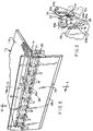
- FIGURE 1 is a fragmentary perspective view of one embodiment of the improved dock leveler assembly showing the barrier member thereof in an operative vehicle barrier position and the lip in a depending, substantially vertical, stored position.
- FIG. 2 is an enlarged fragmentary perspective view of the lever mechanism in partially disassembled relation, shown in FIG. 3 for imparting adjustment of the lip and barrier member independently of the ramp.
- FIG. 3 is a sectional view taken along line 3-3 in FIG. 1.
- FIG. 4 is similar to FIG. 3, but showing the lip in a depending, substantially vertical, stored position and the barrier member in a, non-projecting, inoperative position.
- FIG. 5 is similar to FIG. 4, but showing the lip in an extended cantilevered operative position and the barrier member in a, non-projecting inoperative position.
- FIG. 6 is an enlarged fragmentary sectional view similar to FIG. 5 but of a modified construction.
- FIG. 7 is similar to FIG. 1 but showing components thereof in exploded relation.
- FIG. 8 is a fragmentary perspective front view of selected hinge components for interconnecting the barrier member, lip and ramp.
- the assembly 10 includes a ramp 11, sometimes referred to as a deck, having a rectangular or square configuration.
- the ramp 11 is disposed in registry with a pit or recess, not shown, normally formed in the platform surface of a conventional loading dock such as provided at a commercial or industrial facility.
- the pit has an open top side and a front side which opens at the front wall of the loading dock.
- the peripheral configuration of the ramp corresponds substantially to the shape of the pit top side.
- a rear peripheral segment of the ramp, not shown, may be hingedly connected to a section of a frame 12, see FIG. 3; the latter being fixedly mounted within the pit.
- the connection between the ramp and frame section and the mechanism for hingedly adjusting the ramp relative to the frame section are well known in the dock leveler art, see U.S. Patent Nos. 4,110,860 and 4,995,130 and thus, form no part of the invention hereinafter described.
- the exposed top surface lla of the ramp is horizontal and substantially coplanar with the portions of the platform surface circumjacent the pit open top side.
- the ramp 11 is supported in mode I by a pair of legs 31 resting on frame (12) stop brackets 32 as will be described more fully hereinafter.
- the ramp will not obstruct cross traffic of material handling equipment (e.g. fork-lift trucks) on the dock platform.
- first brackets 15 Fixedly mounted on and protruding from the front face of flange 14 and arranged in laterally spaced, aligned relation are a plurality of first brackets 15, see Fig. 7.
- a barrier member 16 is hingedly connected to the front peripheral segment llb of ramp 11 as seen more clearly in FIGS. 3-5 and 7.
- the barrier member 16, as illustrated may be in the form of a plate. Both lip 13 and plate 16 may extend the full width of ramp 11.
- Lip 13 has a plurality of laterally spaced second brackets 17 projecting from the back surface 13a thereof. Each bracket 15 and 17 is provided with a transversely extending hole 15a and 17a.
- Barrier member 16 is also provided with a plurality of laterally spaced third brackets 18 which project from the back surface 16a thereof.
- brackets 17 are positioned adjacent corresponding sides of brackets 18 so that the bracket holes 17a and 18a are in axial alignment and accommodate an elongate first pintle 20, see Fig. 8.
- brackets 15 are positioned adjacent the opposite corresponding sides of brackets 18 so that the bracket holes 15a and 18b are in axial alignment and accommodate an elongate second pintle 21, see FIG. 8.
- flange 14 is provided with a cutout 14a which is laterally offset a substantial distance from the exposed end 14b of the flange.
- a lever mechanism 22 see Fig. 2, which includes an elongate first lever arm 23 having an apertured end portion 23a which accommodates a portion of pintle 21.
- the opposite end portion 23b of arm 23 is apertured and positioned between a pair of second lever arms 24.
- End portions 24a of arms 24 are pivotally connected to end portion 23b of arm 23 and end portions 24b are pivotally connected to a finger-like portion 25a formed on a bracket 25 affixed to the back surface 13a of the lip 13, see FIG. 2.
- Bracket 25 may be provided with a hole 25b which is sized to accommodate a portion of pintle 20, see FIG. 5.
- the lip and the barrier member may be actuated by means other a piston and hydraulic cylinder, for example, by mechanical, pneumatic, or electromechanical devices, a screw drive, or cables assisted by springs.
- the barrier member 16 is disposed in a vehicle blocking mode, that is to say it is projecting upwardly at substantially a right angle to the exposed ramp surface.
- the lip 13 assumes a vertical depending position, or stored mode, wherein the platform (11) is supported by legs 31.
- the piston 26 is retracted to the fullest extent into the cylinder 27. Movement of the piston between an extended position, Fig. 5, and a fully retracted position, Fig. 3, is manually controlled from a control panel, not shown, normally mounted in a remote, yet secure location.
- the legs and stops are of conventional design and, when in the normal operative mode support platform 11 in the stored position and prevent accidental and sudden downward movement of the ramp below the dock platform surface which, unless checked, might cause a material handling vehicle and/or the product being handled thereby to fall off the dock.
- the lip 13 spans a gap, not shown, which exists between the rear end of the truck bed and the dock front wall.
- the parked truck may be readily loaded and unloaded utilizing a fork-lift truck or other material handling equipment.
- the depending safety foot 31 is pivoted counter-clockwise so as to be out of alignment with stop 32 thereby enabling the ramp with the outwardly extending lip to be pivoted downwardly as a unit so as to assume a declining position.
- the ramp In order for the lip 13 to be moved to an outwardly extending cantilevered position it is necessary that the ramp be initially pivoted upwardly a sufficient amount so that the free edge 13b of the lip clears the rear end of the bed of the parked truck. Once the lip assumes its cantilevered position, the ramp and extended lip are lowered as a unit until the lip comes to rest upon the exposed surface of the truck bed.
- the barrier member 16 overlies the exposed surface of the ramp. If such a relationship is deemed undesirable, the outer edge portion llb of the ramp 11 may be provided with a recess R, see Fig. 6. The depth of the recess is approximately the thickness of the barrier member 16. Thus, when barrier member 16 is in its inoperative mode (i.e. overlying the free edge portion of the ramp) the exposed surface 16a of the barrier member 16 is substantially flush with the exposed ramp surface.
- an improved loading dock leveler which is of simple, yet sturdy construction and has both a pivoting lip and a pivoting barrier member at the front edge of the ramp whereby the pivotal movement of the lip and barrier member are coordinated so that the barrier member can selectively assume either an operative barrier-forming upright position or an inoperative non-projecting position allowing material handling vehicles to load and unload a parked truck.
Landscapes
- Engineering & Computer Science (AREA)
- Mechanical Engineering (AREA)
- Auxiliary Methods And Devices For Loading And Unloading (AREA)
- Vehicle Step Arrangements And Article Storage (AREA)
Claims (7)
- Laderampen-Höhenausgleichsbaugruppe (10) für eine Laderampe, die eine schwenkbar angebrachte Klappe (11) umfaßt, die zwischen einer ersten Position, in der eine freiliegende Fläche (11a) der Klappe im wesentlichen koplanar mit einer Plattformfläche der Laderampe ist, und einer zweiten Position zum Be- und Entladen der Ladefläche eines an der Laderampe abgestellten Fahrzeugs verstellt werden kann, ein Sperrenelement (16), das um eine Achse schwenkbar an einem Vorderkantenabschnitt der Klappe (11) angebracht ist und nach Wahl um die Achse zwischen einer Funktionsposition, in der ein erheblicher Abschnitt des Sperrenelementes (16) winklig über die freiliegende Fläche der Klappe vorsteht, und einer Ruheposition, in der im wesentlichen kein Abschnitt des Sperrenelementes (16) winklig über die freiliegende Fläche der Klappe vorsteht, lediglich geschwenkt werden kann, eine Ansatzverlängerung (13), die mit dem Sperrenelement (16) verbunden ist und zwischen einer ersten Position, in der die Ansatzverlängerung (13) nach unten vorsteht, und einer zweiten Position geschwenkt werden kann, in der die Ansatzverlängerung (13) auslegerartig vorsteht, und ein Betätigungselement (27), das die Ansatzverlängerung (13) zwischen der ersten und der zweiten Position bewegt, dadurch gekennzeichnet, daß die Ansatzverlängerung (13) in der ersten Position von dem Vorderkantenabschnitt der Klappe nach unten vorsteht und in der zweiten Position von der Vorderkante der Rampe auslegerartig vorsteht und einen Zwischenraum überbrückt, der zwischen dem Vorderkantenabschnitt der Klappe und der Ladefläche des abgestellten Fahrzeugs besteht, wobei die Ansatzverlängerung (13) funktionell so mit dem Sperrenelement (16) verbunden ist, daß, wenn sich die Ansatzverlängerung (13) in der ersten Position befindet, das Sperrenelement (16) wahlweise entweder die Funktions- oder die Ruheposition einnehmen kann, und wenn sich die Ansatzverlängerung (13) in der zweiten Position befindet, das Sperrenelement (16) die Ruheposition einnimmt, wobei das Betätigungselement (27) funktionell mit dem Sperrenelement (16) ebenfalls verbunden ist, um die Schwenkbewegung des Sperrenelementes (16) und der Ansatzverlängerung (13) auszulösen und zu koordinieren.
- Laderampen-Höhenausgleichsbaugruppe nach Anspruch 1, wobei eine Halteeinrichtung vorhanden ist, die die Klappe in der ersten Position hält.
- Laderampen-Höhenausgleichsbaugruppe (10) für eine Laderampe, die ein Trägergestell (12) umfaßt, das in einer Grube angebracht werden kann, die in der Plattformfläche der Laderampe ausgebildet ist, eine Klappe (11), die schwenkbar an dem Trägergestell (12) angebracht ist und zwischen einer verstauten Position, in der eine freiliegende Fläche (11a) der Klappe um die Grube herum im wesentlichen koplanar mit der Laderampen-Plattformfläche ist, und einer nicht verstauten Position verstellt werden kann, einen Vorsatzabschnitt (14), der an einem Vorderkantenabschnitt der Klappe (11) angebracht ist und von diesem nach unten vorsteht, ein Sperrenelement (16), das um eine Achse schwenkbar an dem Vorsatzabschnitt (14) angebracht ist und um die Achse zwischen einer Funktionsposition, in der wenigstens ein erheblicher Abschnitt des Sperrenelementes (16) winklig über die freiliegende Fläche der Klappe vorsteht, und einer Ruheposition, in der das Sperrenelement (16) im wesentlichen nicht winklig über die freiliegende Fläche der Klappe vorsteht, lediglich geschwenkt werden kann, eine Ansatzverlängerung (13), die mit dem Sperrenelement (16) verbunden ist und zwischen einer ersten Position, in der die Ansatzverlängerung (13) nach unten vorsteht, und einer zweiten Position geschwenkt werden kann, in der die Ansatzverlängerung (13) eine auslegerartig vorstehende Position einnimmt, und ein Betätigungselement (27), das die Ansatzverlängerung (13) zwischen der ersten und der zweiten Position bewegt, dadurch gekennzeichnet, daß die Ansatzverlängerung (13) in der ersten Position von dem Vorderkantenabschnitt der Klappe nach unten vorsteht und in der zweiten Position von dem Vorderkantenabschnitt der KLappe auslegerartig vorsteht und einen Zwischenraum überbrückt, der zwischen dem Vorderkantenabschnitt der Klappen und der Ladefläche eines abgestellten Fahrzeugs besteht, wobei die Ansatzverlängerung (13) funktionell so mit dem Sperrenelement (16) verbunden ist, daß, wenn sich die Ansatzverlängerung in der ersten Position befindet, das Sperrenelement wahlweise entweder die Funktions- oder die Ruheposition einnehmen kann, und, wenn sich die Ansatzverlängerung in der zweiten Position befindet, das Sperrenelement die Ruheposition einnimmt, wobei das Betätigungselement (27) mit dem Sperrenelement (16) funktionell ebenfalls verbunden ist, um die Schwenkbewegung des Sperrenelementes (16) und der Ansatzverlängerung (13) auszulösen und zu koordinieren.
- Laderampen-Höhenausgleichzbaugruppe nach Anspruch 1 oder 3, wobei die Betätigungseinrichtung eine Kolben-/Zylinder-Einrichtung (26, 27) enthält, wobei ein Zylinder (27) derselben schwenkbar an einer Unterseite (11c) der Klappe (11) angebracht ist und ein Kolben (26) derselben einen freiliegenden Endabschnitt (26a) aufweist, der schwenkbar an einer Hebelbaugruppe (22) angebracht ist, wobei die Hebelbaugruppe eine erste Hebeleinrichtung (23) enthält, die an einem Ende (23a) schwenkbar an einem ersten Abschnitt eines ersten Trägers (18) angebracht ist, der an einer Rückseite (16a) der Sperreneinrichtung befestigt ist, und an einem zweiten Träger (15), der an dem Vorderkantenabschnitt der Klappe befestigt ist, eine zweite Hebeleinrichtung (24), die an einem Ende (24a) schwenkbar an einem zweiten Ende (23b) der ersten Hebeleinrichtung angebracht ist und an einem zweiten Ende (24b) schwenkbar an einem ersten Abschnitt eines dritten Trägers (25) angebracht ist, der an einer Rückseite (13a) der Verlängerungseinrichtung befestigt ist, wobei das freiliegende Ende des Kolbens schwenkbar an dem zweiten Ende der ersten Hebeleinrichtung angebracht ist, ein zweiter Abschnitt des dritten Trägers schwenkbar an einem zweiten Abschnitt des ersten Trägers angebracht ist.
- Laderampen-Höhenausgleichsbaugruppe nach Anspruch 1 oder 3, wobei sowohl das Sperrenelement (16) als auch die Ansatzverlängerung (13) eine Abmessung haben, die im wesentlichen einer Breitenabmessung der Rampe entspricht.
- Laderampen-Höhenausgleichsbaugruppe nach Anspruch 5, wobei das Sperrenelement (16) und die Ansatzverlängerung (13) aus Plattenmaterial bestehen.
- Laderampen-Höhenausgleichsbaugruppe nach Anspruch 6, wobei der Vorderkantenabschnitt der Klappe mit einer Vertiefung (R) versehen ist, deren Tiefe im wesentlichen der Dicke des Plattenmaterials des Sperrenelementes (16) entspricht, so daß, wenn sich das Sperrenelement (16) in der Ruheposition befindet, eine freiliegende Fläche des Sperrenelementes (16) im wesentlichen koplanar mit der freiliegenden Fläche der Klappe (11) ist.
Applications Claiming Priority (3)
| Application Number | Priority Date | Filing Date | Title |
|---|---|---|---|
| US894087 | 1992-06-05 | ||
| US07/894,087 US5311628A (en) | 1992-06-05 | 1992-06-05 | Dock leveler with an improved automatic material handling vehicle barrier |
| PCT/US1993/005330 WO1993025763A1 (en) | 1992-06-05 | 1993-06-03 | Dock leveler with an improved automatic material handling vehicle barrier |
Publications (3)
| Publication Number | Publication Date |
|---|---|
| EP0601176A1 EP0601176A1 (de) | 1994-06-15 |
| EP0601176A4 EP0601176A4 (en) | 1994-06-29 |
| EP0601176B1 true EP0601176B1 (de) | 1996-12-11 |
Family
ID=25402588
Family Applications (1)
| Application Number | Title | Priority Date | Filing Date |
|---|---|---|---|
| EP93916431A Expired - Lifetime EP0601176B1 (de) | 1992-06-05 | 1993-06-03 | Vorrichtung zur höhenanpassung einer laderampe mit verbesserter automatischer schranke für materialbearbeitende fahrzeuge |
Country Status (7)
| Country | Link |
|---|---|
| US (1) | US5311628A (de) |
| EP (1) | EP0601176B1 (de) |
| CA (1) | CA2114031C (de) |
| DE (1) | DE69306540T2 (de) |
| ES (1) | ES2068147B1 (de) |
| MX (1) | MX9303413A (de) |
| WO (1) | WO1993025763A1 (de) |
Families Citing this family (44)
| Publication number | Priority date | Publication date | Assignee | Title |
|---|---|---|---|---|
| GB2291636A (en) * | 1994-07-26 | 1996-01-31 | Westinghouse Brake & Signal | Vehicle gap bridge |
| US5553343A (en) * | 1995-03-06 | 1996-09-10 | United Dominion Industries, Inc. | Dock leveler with folding barrier lip |
| US5781953A (en) * | 1996-07-22 | 1998-07-21 | Overhead Door Corporation | Dock leveler ramp |
| US5936038A (en) * | 1996-08-09 | 1999-08-10 | The University Of Akron | Vulcanizable elastomeric composition and thermoplastic vulcanizate employing the same |
| US6276016B1 (en) * | 1997-04-15 | 2001-08-21 | Rite-Hite Holding Corporation | Safety leg system for dock leveler |
| US6085375A (en) * | 1998-06-22 | 2000-07-11 | Rite-Hite Holding Corporation | Lip guiding mechanism for dock levelers |
| US6516487B1 (en) | 1999-11-12 | 2003-02-11 | Kelley Atlantic Ltd. | Dockleveler with a barrier |
| US6442783B1 (en) | 2000-06-12 | 2002-09-03 | Genquip Corporation | Dock leveler with run-off barrier configuration |
| US6370719B1 (en) * | 2000-08-14 | 2002-04-16 | United Dominion Industries, Inc. | Dock leveler lip construction |
| US6842930B2 (en) | 2001-02-09 | 2005-01-18 | Spx Dock Products Inc. | Run-off guard for a dock leveler |
| US6880301B2 (en) * | 2001-03-06 | 2005-04-19 | Rite-Hite Holding Corporation | Pivotal and translational dock leveler lip |
| US6405397B1 (en) * | 2001-05-21 | 2002-06-18 | United Dominion Industries | Loading dock with segmented wide lip |
| DE10157795B4 (de) * | 2001-11-27 | 2010-07-01 | Niclas Grunewald | Überladebrücke mit Absturzsicherung |
| US20040031110A1 (en) * | 2002-08-19 | 2004-02-19 | Kelley Atlantic Ltd. | Dockleveler with a barrier |
| USD579754S1 (en) * | 2002-12-23 | 2008-11-04 | Denis Gleason | Lip and hinge plate for a dock leveler |
| US6931686B2 (en) * | 2003-03-12 | 2005-08-23 | Spx Dock Products Inc. | Support leg system and method for supporting a dock leveler |
| US7047584B2 (en) * | 2003-03-12 | 2006-05-23 | Spx Dock Products, Inc. | Support leg system and method for supporting a dock leveler |
| US7062813B2 (en) | 2003-03-12 | 2006-06-20 | Spx Dock Products, Inc. | Support leg system and method for supporting a dock leveler |
| US7216391B2 (en) | 2003-12-18 | 2007-05-15 | Rite-Hite Holding Corporation | Constant radius dock leveler hinge |
| US7134159B2 (en) * | 2004-01-13 | 2006-11-14 | Rite-Hite Holding Corporation | Stump-out apparatus for a dock leveler |
| US7032267B2 (en) * | 2004-05-11 | 2006-04-25 | Rite-Hite Holding Corporation | Dock leveler with combination safety leg and lip deflector |
| US7213285B2 (en) * | 2004-08-12 | 2007-05-08 | Rite-Hite Holding Corporation | Pivotal and vertically translatable dock leveler lip |
| US20060123569A1 (en) * | 2004-12-14 | 2006-06-15 | Rite-Hite Holding Corporation | Dock leveler lip providing multi-position barrier |
| US20080184503A1 (en) * | 2007-02-02 | 2008-08-07 | Rite-Hite Holding Corporation | Smooth transition dock leveler lip |
| US8544130B2 (en) | 2010-07-14 | 2013-10-01 | Rite-Hite Holding Corporation | Curved transition plates for pivotal dock leveler decks |
| US8869332B1 (en) | 2013-05-28 | 2014-10-28 | Grant Leum | Mobile loading dock with slot-engaging member |
| US9169090B2 (en) | 2013-05-28 | 2015-10-27 | Grant Leum | Mobile loading dock with wheel assembly |
| US9428350B2 (en) | 2013-05-28 | 2016-08-30 | Grant Leum | Mobile loading dock with free fall protection |
| US8869334B1 (en) | 2013-05-28 | 2014-10-28 | Grant Leum | Mobile loading dock with load-bearing frame |
| US9051136B2 (en) | 2013-11-11 | 2015-06-09 | Grant Leum | Mobile loading dock with adjustable leg assembly |
| US9260258B1 (en) | 2015-01-29 | 2016-02-16 | Grant Leum | Removable dock barrier |
| USD769695S1 (en) * | 2015-03-23 | 2016-10-25 | Nordock, Inc. | Sliding barrier dock leveler |
| CN105059965B (zh) * | 2015-07-31 | 2017-06-30 | 上海宝冶集团有限公司 | 用于码头原料装卸的落料挡板 |
| US20170073176A1 (en) * | 2015-09-11 | 2017-03-16 | Blue Giant Equipment Corporation | T-bolt for dock lip |
| US9688493B2 (en) | 2015-11-09 | 2017-06-27 | Grant Leum | Mobile loading dock with side extensions |
| US9938094B1 (en) * | 2017-03-06 | 2018-04-10 | Leum Engineering, Inc. | Dock leveler with safety barrier |
| US9944475B1 (en) * | 2017-03-06 | 2018-04-17 | Leum Engineering, Inc. | Dock leveler |
| CA3032716C (en) * | 2018-02-06 | 2026-04-21 | Produits Hevea Inc. | Shock absorbing dock leveler lip |
| US11254527B2 (en) * | 2019-04-05 | 2022-02-22 | Safe Rack Llc | Gangway having self-raising assembly |
| US11273999B1 (en) * | 2020-09-04 | 2022-03-15 | Leum Engineering, Inc. | Modular loading dock with integrated leveler |
| US12583695B2 (en) | 2022-05-12 | 2026-03-24 | Overhead Door Corporation | Dock leveler |
| US12319523B2 (en) | 2022-05-12 | 2025-06-03 | Overhead Door Corporatior | Dock leveler with lip hinge |
| US12522455B2 (en) | 2022-05-12 | 2026-01-13 | Overhead Door Corporation | Dock leveler with deck hinge |
| US12589956B2 (en) | 2023-06-09 | 2026-03-31 | Overhead Door Corporation | Dock leveler with shimless pivot boss |
Family Cites Families (6)
| Publication number | Priority date | Publication date | Assignee | Title |
|---|---|---|---|---|
| US3426377A (en) * | 1967-05-03 | 1969-02-11 | Loomis Machine Co | Dockboard |
| US3636578A (en) * | 1969-06-20 | 1972-01-25 | Overhead Door Corp | Spring counterbalanced compact dockboard |
| US3806976A (en) * | 1972-03-17 | 1974-04-30 | Woodford Mfg Co | Dock plate |
| US4920598A (en) * | 1988-10-13 | 1990-05-01 | Rite-Hite Corporation | Dock leveler with automatic vehicle barrier |
| US5040258A (en) * | 1990-05-23 | 1991-08-20 | Rite-Hite Corporation | Dock leveler with automatic vehicle barrier |
| US5157801A (en) * | 1991-01-30 | 1992-10-27 | The Serco Corporation | Dock leveler having automatically actuated vehicle barrier |
-
1992
- 1992-06-05 US US07/894,087 patent/US5311628A/en not_active Expired - Fee Related
-
1993
- 1993-06-03 DE DE69306540T patent/DE69306540T2/de not_active Expired - Fee Related
- 1993-06-03 WO PCT/US1993/005330 patent/WO1993025763A1/en not_active Ceased
- 1993-06-03 CA CA002114031A patent/CA2114031C/en not_active Expired - Fee Related
- 1993-06-03 EP EP93916431A patent/EP0601176B1/de not_active Expired - Lifetime
- 1993-06-04 ES ES09301239A patent/ES2068147B1/es not_active Expired - Lifetime
- 1993-06-07 MX MX9303413A patent/MX9303413A/es not_active IP Right Cessation
Also Published As
| Publication number | Publication date |
|---|---|
| ES2068147B1 (es) | 1998-02-16 |
| US5311628A (en) | 1994-05-17 |
| ES2068147A2 (es) | 1995-04-01 |
| EP0601176A4 (en) | 1994-06-29 |
| DE69306540D1 (de) | 1997-01-23 |
| ES2068147R (de) | 1997-07-16 |
| DE69306540T2 (de) | 1997-06-19 |
| MX9303413A (es) | 1994-04-29 |
| EP0601176A1 (de) | 1994-06-15 |
| CA2114031C (en) | 1996-09-03 |
| WO1993025763A1 (en) | 1993-12-23 |
| CA2114031A1 (en) | 1993-12-23 |
Similar Documents
| Publication | Publication Date | Title |
|---|---|---|
| EP0601176B1 (de) | Vorrichtung zur höhenanpassung einer laderampe mit verbesserter automatischer schranke für materialbearbeitende fahrzeuge | |
| CA1317745C (en) | Dock leveler assembly and latching mechanism therefor | |
| EP0634349B1 (de) | Ladeplattform mit automatischer Barriere für Fahrzeuge | |
| US4920598A (en) | Dock leveler with automatic vehicle barrier | |
| EP0419787B1 (de) | Schwenkrampe mit Hebeplattform und Betriebsverfahren | |
| US6634049B2 (en) | Moveable bumper for a dock leveler | |
| EP1012091B1 (de) | Sicherheitsstützessystem für eine ladebrücke | |
| US4110860A (en) | Leveler assembly for a loading dock | |
| CA2336804C (en) | Dock leveler with integral bumpers | |
| EP1368264B1 (de) | Schwenkrampe mit dreh- und gleitbewegbar angeordneter verlängerung | |
| US20050172426A1 (en) | Vertically-storing dock leveler apparatus and method | |
| US5452489A (en) | Dock leveler with automatic end barrier | |
| US6499169B2 (en) | Recycle control system for dock levelers | |
| US6842930B2 (en) | Run-off guard for a dock leveler | |
| US20060123569A1 (en) | Dock leveler lip providing multi-position barrier | |
| CA2575236A1 (en) | Pivotal and translational dock leveler lip |
Legal Events
| Date | Code | Title | Description |
|---|---|---|---|
| PUAI | Public reference made under article 153(3) epc to a published international application that has entered the european phase |
Free format text: ORIGINAL CODE: 0009012 |
|
| 17P | Request for examination filed |
Effective date: 19940215 |
|
| AK | Designated contracting states |
Kind code of ref document: A1 Designated state(s): DE FR GB IT NL |
|
| A4 | Supplementary search report drawn up and despatched |
Effective date: 19940506 |
|
| AK | Designated contracting states |
Kind code of ref document: A4 Designated state(s): DE FR GB IT NL |
|
| 17Q | First examination report despatched |
Effective date: 19950807 |
|
| GRAG | Despatch of communication of intention to grant |
Free format text: ORIGINAL CODE: EPIDOS AGRA |
|
| GRAH | Despatch of communication of intention to grant a patent |
Free format text: ORIGINAL CODE: EPIDOS IGRA |
|
| GRAH | Despatch of communication of intention to grant a patent |
Free format text: ORIGINAL CODE: EPIDOS IGRA |
|
| GRAA | (expected) grant |
Free format text: ORIGINAL CODE: 0009210 |
|
| AK | Designated contracting states |
Kind code of ref document: B1 Designated state(s): DE FR GB IT NL |
|
| PG25 | Lapsed in a contracting state [announced via postgrant information from national office to epo] |
Ref country code: NL Free format text: LAPSE BECAUSE OF FAILURE TO SUBMIT A TRANSLATION OF THE DESCRIPTION OR TO PAY THE FEE WITHIN THE PRESCRIBED TIME-LIMIT Effective date: 19961211 Ref country code: IT Free format text: LAPSE BECAUSE OF FAILURE TO SUBMIT A TRANSLATION OF THE DESCRIPTION OR TO PAY THE FEE WITHIN THE PRE;WARNING: LAPSES OF ITALIAN PATENTS WITH EFFECTIVE DATE BEFORE 2007 MAY HAVE OCCURRED AT ANY TIME BEFORE 2007. THE CORRECT EFFECTIVE DATE MAY BE DIFFERENT FROM THE ONE RECORDED.SCRIBED TIME-LIMIT Effective date: 19961211 |
|
| REF | Corresponds to: |
Ref document number: 69306540 Country of ref document: DE Date of ref document: 19970123 |
|
| ET | Fr: translation filed | ||
| NLV1 | Nl: lapsed or annulled due to failure to fulfill the requirements of art. 29p and 29m of the patents act | ||
| PLBE | No opposition filed within time limit |
Free format text: ORIGINAL CODE: 0009261 |
|
| STAA | Information on the status of an ep patent application or granted ep patent |
Free format text: STATUS: NO OPPOSITION FILED WITHIN TIME LIMIT |
|
| 26N | No opposition filed | ||
| REG | Reference to a national code |
Ref country code: GB Ref legal event code: IF02 |
|
| PGFP | Annual fee paid to national office [announced via postgrant information from national office to epo] |
Ref country code: GB Payment date: 20020529 Year of fee payment: 10 |
|
| PGFP | Annual fee paid to national office [announced via postgrant information from national office to epo] |
Ref country code: FR Payment date: 20020610 Year of fee payment: 10 |
|
| PGFP | Annual fee paid to national office [announced via postgrant information from national office to epo] |
Ref country code: DE Payment date: 20020612 Year of fee payment: 10 |
|
| PG25 | Lapsed in a contracting state [announced via postgrant information from national office to epo] |
Ref country code: GB Free format text: LAPSE BECAUSE OF NON-PAYMENT OF DUE FEES Effective date: 20030603 |
|
| PG25 | Lapsed in a contracting state [announced via postgrant information from national office to epo] |
Ref country code: DE Free format text: LAPSE BECAUSE OF NON-PAYMENT OF DUE FEES Effective date: 20040101 |
|
| GBPC | Gb: european patent ceased through non-payment of renewal fee |
Effective date: 20030603 |
|
| PG25 | Lapsed in a contracting state [announced via postgrant information from national office to epo] |
Ref country code: FR Free format text: LAPSE BECAUSE OF NON-PAYMENT OF DUE FEES Effective date: 20040227 |
|
| REG | Reference to a national code |
Ref country code: FR Ref legal event code: ST |