EP0601253B1 - Heizkessel aus Gusseisen - Google Patents
Heizkessel aus Gusseisen Download PDFInfo
- Publication number
- EP0601253B1 EP0601253B1 EP19920440140 EP92440140A EP0601253B1 EP 0601253 B1 EP0601253 B1 EP 0601253B1 EP 19920440140 EP19920440140 EP 19920440140 EP 92440140 A EP92440140 A EP 92440140A EP 0601253 B1 EP0601253 B1 EP 0601253B1
- Authority
- EP
- European Patent Office
- Prior art keywords
- boiler
- fact
- accordance
- gasket
- elements
- Prior art date
- Legal status (The legal status is an assumption and is not a legal conclusion. Google has not performed a legal analysis and makes no representation as to the accuracy of the status listed.)
- Expired - Lifetime
Links
Images


Classifications
-
- F—MECHANICAL ENGINEERING; LIGHTING; HEATING; WEAPONS; BLASTING
- F24—HEATING; RANGES; VENTILATING
- F24H—FLUID HEATERS, e.g. WATER OR AIR HEATERS, HAVING HEAT-GENERATING MEANS, e.g. HEAT PUMPS, IN GENERAL
- F24H1/00—Water heaters, e.g. boilers, continuous-flow heaters or water-storage heaters
- F24H1/22—Water heaters other than continuous-flow or water-storage heaters, e.g. water heaters for central heating
- F24H1/24—Water heaters other than continuous-flow or water-storage heaters, e.g. water heaters for central heating with water mantle surrounding the combustion chamber or chambers
- F24H1/30—Water heaters other than continuous-flow or water-storage heaters, e.g. water heaters for central heating with water mantle surrounding the combustion chamber or chambers the water mantle being built up from sections
- F24H1/32—Water heaters other than continuous-flow or water-storage heaters, e.g. water heaters for central heating with water mantle surrounding the combustion chamber or chambers the water mantle being built up from sections with vertical sections arranged side by side
-
- F—MECHANICAL ENGINEERING; LIGHTING; HEATING; WEAPONS; BLASTING
- F24—HEATING; RANGES; VENTILATING
- F24H—FLUID HEATERS, e.g. WATER OR AIR HEATERS, HAVING HEAT-GENERATING MEANS, e.g. HEAT PUMPS, IN GENERAL
- F24H9/00—Details
- F24H9/14—Arrangements for connecting different sections, e.g. in water heaters
-
- F—MECHANICAL ENGINEERING; LIGHTING; HEATING; WEAPONS; BLASTING
- F24—HEATING; RANGES; VENTILATING
- F24H—FLUID HEATERS, e.g. WATER OR AIR HEATERS, HAVING HEAT-GENERATING MEANS, e.g. HEAT PUMPS, IN GENERAL
- F24H9/00—Details
- F24H9/14—Arrangements for connecting different sections, e.g. in water heaters
- F24H9/146—Connecting elements of a heat exchanger
Definitions
- the present invention relates to cast iron boilers whose hydraulic circuit is formed from a set of molded elements obtained without the use of foundry cores.
- Such boilers are known in principle, for example by European Patent Application No. EP-A-0 414 925 and the published German Patent Application DE 41 19 866 C1. They are formed by assembling such elements delimiting an internal volume traversed by the combustion products and an external or peripheral volume traversed by the water of the heating circuit. This external volume must therefore both offer the minimum resistance to the circulation of water from each element to the next and a perfect seal.
- the elements are cylindrical boxes having an H-shaped axial section (with the exception of the end elements) and are assembled facing each other along their open sides, with interposition of seals, all of these boxes and said seals being compressed by means of a series of tensioned tie rods internally traversing the entire length of the boxes, being distributed peripherally at the rate of one tie for each section formed of a longitudinal series of boxes. Any axial movement of boxes is therefore practically impossible.
- such an assembly implying the installation of as many tie rods as boxes in a cross section and their tensioning uniformly distributed, is Obviously long and complicated, especially in case of disassembly for the maintenance or replacement of said boxes.
- sealing must be ensured at the end of each tie rod.
- the present invention eliminates the various drawbacks which emerge from the above description of the state of the art, that is to say the complexity of the parts and their assembly and in particular the need to ensure their tightening by means tight tie rods.
- the water circuit of a boiler consists of a succession of sections of cast iron ferrules, each section being slightly frustoconical in at least one direction so that its small face comes to adapt tightly in the large face of a contiguous section, all of the assembled sections constituting a toroidal volume, the two peripheral surfaces of which are kept apart by annular transverse spacers pierced with openings allowing the circulation of water in the axial direction, said assembly being held by means of tie rods external to the boxes, bearing on ears distributed over the periphery of the end ferrules.
- all the sections of ferrules are oriented in the same direction, the large face of each section constituting the spacer corresponding to the corresponding cross section of the boiler.
- the front edge of the small face of each section abuts against the large rear face of the neighboring section, the seal being ensured by an appropriate seal.
- the sections are oriented alternately in one direction and in the other, the assembly being done by the small facing faces of two successive sections with the interposition of a thin annular piece itself constituting both the and the gasket.
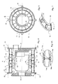
- FIG. 1-2 there is shown a boiler according to the invention consisting in known manner of a heating body 1 completed by an insulated front panel A and a rear panel B through which are evacuated combustion products.
- the invention provides for the assembly of two series of cast iron ferrules 4 and 5 , slightly frustoconical so that the edge of the small front face 6 a of an outer shell 4 a abuts against the large rear face 7 b of the next outer shell 4 b , and that likewise, the edge of the small face 6 ' a of an interior ferrule abuts against the large face 7' b of the following interior ferrule, each embedding being sealed by means of a lining 8, for example made of silicone or the like.
- the positioning or centering of a small face with respect to a large face can be ensured by a peripheral rim thereof, or by a number of ribs 17 distributed over the outer periphery of the outer ferrules 4, as shown.
- each pair of ferrules 4-5 and its spacer 9 constitutes a single circular piece of cast iron with a U-section, obtained by casting without a core, so that a boiler thus produced according to the invention by simple axial assembly d 'a series of such circular parts is much simpler and more robust in construction than the previous boilers described above.
- Such an assembly is obtained by means of tie rods 21 exterior to the exterior ferrules 4 passing through ears 18 distributed over the periphery of the exterior ferrules of ends to ensure solidity and tightness, and the tension of which is ensured by means of nuts 22.
- the interior and exterior ferrules, respectively 10 and 11 are oriented alternately in one direction and in the other, so that their small faces are facing each other, and that they are assembled, as illustrated in FIG. 4 A by an intermediate piece 12 constituting an annular spacer comprising water circulation openings (13).
- a part 23 inserted between two pairs of ferrules 10a, 10b, 11a, 11b can itself constitute the seal ensuring the seal between these ferrules. In this case, it may have the appearance of a metallo-plastic joint as shown in FIG. 5, where a gasket 23 having openings 14 is crimped in a metal strip 15.
- the ferrules 10 and 11 are obtained together by coreless casting and assembled by external tie rods 21 tightened by nuts 22.
- the end pieces are similar to those of the first version, while the intermediate pieces are symmetrical about their mid-section.
- FIGS. 2 and 5 illustrate a circular toroidal shape for the water circuit produced according to the invention, it can be produced in an equivalent manner in polygonal form, the peripheral surface of each ferrule 4, 5, 10 and 11 then being formed of a succession of planes.
Landscapes
- Engineering & Computer Science (AREA)
- Physics & Mathematics (AREA)
- Thermal Sciences (AREA)
- Chemical & Material Sciences (AREA)
- Combustion & Propulsion (AREA)
- Mechanical Engineering (AREA)
- General Engineering & Computer Science (AREA)
- Details Of Fluid Heaters (AREA)
- Housings, Intake/Discharge, And Installation Of Fluid Heaters (AREA)
Claims (6)
- Kessel vom Typ, bei dem der hydraulische Kreislauf durch Zusammenbau von in einem Gießverfahren durch kernloses Gießen erhaltenen Elementen gebildet ist,
dadurch gekennzeichnet,
daß jedes der Elemente ein transversales, gießtechnisch hergestelltes, einzelnes Teilstück des Kessels bildet, das von einem Paar von konzentrischen, leicht kegelstumpfartig ausgebildeten Kesselschüssen (4,5,10,11) begrenzt ist, welche von einem Ringelement (9,12) mit Öffnungen (20, 13) für die Zirkulation von Wasser im Abstand gehalten sind, wobei die aufeinanderfolgenden Teilstücke durch äußere, mittels Muttern (22) angezogene Spannelemente, die durch Lappen (18) der äußeren Kesselschüsse hindurchtreten, mit Einfügung einer Dichtung (8,12) zwischen der Peripherie eines Kesselschusses und dem Boden des folgenden zusammengefügt sind. - Kessel nach Anspruch 1,
dadurch gekennzeichnet,
daß die Elemente aller Teilstücke im gleichen Sinn orientiert sind, wobei die kleine Fläche (6a) eines Kesselschusses gegen die große Fläche (7b) des folgenden anliegt. - Kessel nach Anspruch 1,
dadurch gekennzeichnet,
daß die Elemente eines Teilstücks mit Ausnahme der am Ende angeordneten Teilstücke in der aus einem einzigen Gußteil gebildeten Zusammenfügung aus zwei Paaren von leicht kegelstumpfartigen in entgegengesetztem Sinn orientierten Kesselschüssen bestehen und daß deren große Flächen über ein Ringelement (12) mit Öffnungen (13) für die Zirkulation von Wasser einstückig verbunden sind, und daß die kleinen Flächen (11a,11b,10a,10b) zweier solcher aufeinanderfolgender Teilstücke unter Einfügung eines perforierten ringförmigen Teils (23) zusammengefügt sind, wobei die zwei Flächen des ringförmigen Teils (23) die kleinen Flächen der zwei benachbarten Elemente mit einer dazwischen angeordneten Dichtung aufnehmen. - Kessel nach Anspruch 3,
dadurch gekennzeichnet,
daß das ringförmige Teil (23), welches die kleinen Flächen aufnimmt, selbst ein gemeinsames Verbindungsstück bildet. - Kessel nach Anspruch 4,
dadurch gekennzeichnet,
daß das gemeinsame Verbindungsstück ein Verbindungsstück aus Metall und Plastik ist, welches von einem Öffnungen (14) aufweisenden und in ein metallisches Band (15) eingesetzten Band (23) gebildet ist. - Kessel nach einem der vorstehenden Ansprüche,
dadurch gekennzeichnet,
daß jeder innere Kesselschuss mit Rippen (17) ausgebildet ist, die gegen den Feuerungsraum gerichtet sind, um den Wärmeaustausch zu verbessern.
Priority Applications (2)
| Application Number | Priority Date | Filing Date | Title |
|---|---|---|---|
| EP19920440140 EP0601253B1 (de) | 1992-12-07 | 1992-12-07 | Heizkessel aus Gusseisen |
| DE1992603607 DE69203607T2 (de) | 1992-12-07 | 1992-12-07 | Heizkessel aus Gusseisen. |
Applications Claiming Priority (1)
| Application Number | Priority Date | Filing Date | Title |
|---|---|---|---|
| EP19920440140 EP0601253B1 (de) | 1992-12-07 | 1992-12-07 | Heizkessel aus Gusseisen |
Publications (2)
| Publication Number | Publication Date |
|---|---|
| EP0601253A1 EP0601253A1 (de) | 1994-06-15 |
| EP0601253B1 true EP0601253B1 (de) | 1995-07-19 |
Family
ID=8211777
Family Applications (1)
| Application Number | Title | Priority Date | Filing Date |
|---|---|---|---|
| EP19920440140 Expired - Lifetime EP0601253B1 (de) | 1992-12-07 | 1992-12-07 | Heizkessel aus Gusseisen |
Country Status (2)
| Country | Link |
|---|---|
| EP (1) | EP0601253B1 (de) |
| DE (1) | DE69203607T2 (de) |
Family Cites Families (3)
| Publication number | Priority date | Publication date | Assignee | Title |
|---|---|---|---|---|
| DE4035138A1 (de) * | 1990-11-06 | 1992-05-07 | Viessmann Hans | Heizkessel zum verbrennen fluessiger oder gasfoermiger brennstoffe |
| DE4103238A1 (de) * | 1991-02-02 | 1992-08-13 | Buderus Heiztechnik Gmbh | Gliederheizkessel aus gusseisernen kesselgliedern |
| DE4119866C1 (en) * | 1991-06-17 | 1992-06-17 | Buderus Heiztechnik Gmbh, 6330 Wetzlar, De | Cast-iron@ boiler made in sections - has inner skin elements with outer flanges and outer skin elements with inner flanges |
-
1992
- 1992-12-07 EP EP19920440140 patent/EP0601253B1/de not_active Expired - Lifetime
- 1992-12-07 DE DE1992603607 patent/DE69203607T2/de not_active Expired - Fee Related
Also Published As
| Publication number | Publication date |
|---|---|
| DE69203607T2 (de) | 1996-02-22 |
| EP0601253A1 (de) | 1994-06-15 |
| DE69203607D1 (de) | 1995-08-24 |
Similar Documents
| Publication | Publication Date | Title |
|---|---|---|
| WO2008107606A2 (fr) | Structure cylindrique composee d'elements rectangulaires | |
| FR2582854A1 (fr) | Manchon pour proteger les epissures de cables et procede s'y rapportant | |
| EP0601253B1 (de) | Heizkessel aus Gusseisen | |
| EP0186217A1 (de) | Rahmen | |
| FR2571839A1 (fr) | Perfectionnements aux plaques tubulaires d'echangeurs thermiques | |
| CA2130331C (fr) | Elements de cloison a briques de verre | |
| FR2472123A1 (fr) | Element d'etancheite de conduits, notamment pour moteur a combustion interne | |
| FR2468081A1 (fr) | Capteur solaire | |
| FR2559872A1 (fr) | Soupape unidirectionnelle de retenue de fluides | |
| CA1299026C (fr) | Ensemble embouti pour la combustion pulsatoire | |
| WO2001002777A1 (fr) | Dispositif de liaison a bride a haute rigidite | |
| EP0774027A1 (de) | Unterirdischer durchgang | |
| FR2561357A1 (fr) | Enceinte de four menager et son procede de fabrication | |
| FR2477754A1 (fr) | Element combustible pour reacteur nucleaire, en particulier pour reacteur surregenerateur ou convertisseur | |
| FR2761453A1 (fr) | Piece destinee en particulier a la fixation de deux corps de chauffe d'un radiateur de chauffage | |
| FR2627572A1 (fr) | Dispositif d'etancheite pour joint a emboitement entre deux tuyaux | |
| EP4405629B1 (de) | Vorrichtung zur abgabe einer wärmeübertragungsflüssigkeit | |
| FR2708983A1 (fr) | Bague d'étanchéité destinée à être disposée entre deux brides. | |
| EP1197707B1 (de) | Mit einem Zwischenstück angeschlossene Rohrstücke und Verbindungsverfahren | |
| FR2692162A3 (fr) | Module filtrant. | |
| FR2659108A1 (fr) | Piece d'assemblage de cadre pour vitrage multiple. | |
| FR2604246A1 (fr) | Echangeur de chaleur modulaire. | |
| FR2767151A1 (fr) | Boisseau de cheminee, destine notamment a etre place au niveau d'une traversee de toit | |
| EP0914188B1 (de) | Hochtemperaturfilter, insbesondere für eine lackieranlage | |
| FR2599461A1 (fr) | Corps tubulaire en beton arme de grandes dimensions, equipe d'une tole interieure d'etancheite |
Legal Events
| Date | Code | Title | Description |
|---|---|---|---|
| PUAI | Public reference made under article 153(3) epc to a published international application that has entered the european phase |
Free format text: ORIGINAL CODE: 0009012 |
|
| 17P | Request for examination filed |
Effective date: 19921212 |
|
| AK | Designated contracting states |
Kind code of ref document: A1 Designated state(s): BE CH DE ES FR GB IT LI NL |
|
| GRAA | (expected) grant |
Free format text: ORIGINAL CODE: 0009210 |
|
| AK | Designated contracting states |
Kind code of ref document: B1 Designated state(s): BE CH DE ES FR GB IT LI NL |
|
| PG25 | Lapsed in a contracting state [announced via postgrant information from national office to epo] |
Ref country code: NL Free format text: LAPSE BECAUSE OF FAILURE TO SUBMIT A TRANSLATION OF THE DESCRIPTION OR TO PAY THE FEE WITHIN THE PRESCRIBED TIME-LIMIT Effective date: 19950719 Ref country code: GB Effective date: 19950719 Ref country code: ES Free format text: THE PATENT HAS BEEN ANNULLED BY A DECISION OF A NATIONAL AUTHORITY Effective date: 19950719 |
|
| REF | Corresponds to: |
Ref document number: 69203607 Country of ref document: DE Date of ref document: 19950824 |
|
| ITF | It: translation for a ep patent filed | ||
| PG25 | Lapsed in a contracting state [announced via postgrant information from national office to epo] |
Ref country code: BE Effective date: 19951231 |
|
| NLV1 | Nl: lapsed or annulled due to failure to fulfill the requirements of art. 29p and 29m of the patents act | ||
| PGFP | Annual fee paid to national office [announced via postgrant information from national office to epo] |
Ref country code: CH Payment date: 19960103 Year of fee payment: 4 |
|
| GBV | Gb: ep patent (uk) treated as always having been void in accordance with gb section 77(7)/1977 [no translation filed] |
Effective date: 19950719 |
|
| PLBE | No opposition filed within time limit |
Free format text: ORIGINAL CODE: 0009261 |
|
| BERE | Be: lapsed |
Owner name: DE DIETRICH THERMIQUE Effective date: 19951231 |
|
| 26N | No opposition filed | ||
| PG25 | Lapsed in a contracting state [announced via postgrant information from national office to epo] |
Ref country code: LI Effective date: 19961231 Ref country code: CH Effective date: 19961231 |
|
| REG | Reference to a national code |
Ref country code: CH Ref legal event code: PL |
|
| PGFP | Annual fee paid to national office [announced via postgrant information from national office to epo] |
Ref country code: DE Payment date: 19971203 Year of fee payment: 6 |
|
| PGFP | Annual fee paid to national office [announced via postgrant information from national office to epo] |
Ref country code: FR Payment date: 19971229 Year of fee payment: 6 |
|
| PG25 | Lapsed in a contracting state [announced via postgrant information from national office to epo] |
Ref country code: FR Free format text: LAPSE BECAUSE OF NON-PAYMENT OF DUE FEES Effective date: 19990831 |
|
| REG | Reference to a national code |
Ref country code: FR Ref legal event code: ST |
|
| PG25 | Lapsed in a contracting state [announced via postgrant information from national office to epo] |
Ref country code: DE Free format text: LAPSE BECAUSE OF NON-PAYMENT OF DUE FEES Effective date: 19991001 |
|
| PG25 | Lapsed in a contracting state [announced via postgrant information from national office to epo] |
Ref country code: IT Free format text: LAPSE BECAUSE OF NON-PAYMENT OF DUE FEES;WARNING: LAPSES OF ITALIAN PATENTS WITH EFFECTIVE DATE BEFORE 2007 MAY HAVE OCCURRED AT ANY TIME BEFORE 2007. THE CORRECT EFFECTIVE DATE MAY BE DIFFERENT FROM THE ONE RECORDED. Effective date: 20051207 |