EP0601304A1 - Verfahren und Anordnung zur Erkennung von Bit-Sequenzen in Datenströmen - Google Patents
Verfahren und Anordnung zur Erkennung von Bit-Sequenzen in Datenströmen Download PDFInfo
- Publication number
- EP0601304A1 EP0601304A1 EP93116507A EP93116507A EP0601304A1 EP 0601304 A1 EP0601304 A1 EP 0601304A1 EP 93116507 A EP93116507 A EP 93116507A EP 93116507 A EP93116507 A EP 93116507A EP 0601304 A1 EP0601304 A1 EP 0601304A1
- Authority
- EP
- European Patent Office
- Prior art keywords
- data
- sequences
- byte
- bit
- text
- Prior art date
- Legal status (The legal status is an assumption and is not a legal conclusion. Google has not performed a legal analysis and makes no representation as to the accuracy of the status listed.)
- Granted
Links
Images




Classifications
-
- G—PHYSICS
- G06—COMPUTING OR CALCULATING; COUNTING
- G06F—ELECTRIC DIGITAL DATA PROCESSING
- G06F7/00—Methods or arrangements for processing data by operating upon the order or content of the data handled
- G06F7/02—Comparing digital values
-
- G—PHYSICS
- G06—COMPUTING OR CALCULATING; COUNTING
- G06F—ELECTRIC DIGITAL DATA PROCESSING
- G06F3/00—Input arrangements for transferring data to be processed into a form capable of being handled by the computer; Output arrangements for transferring data from processing unit to output unit, e.g. interface arrangements
- G06F3/12—Digital output to print unit, e.g. line printer, chain printer
- G06F3/1201—Dedicated interfaces to print systems
- G06F3/1202—Dedicated interfaces to print systems specifically adapted to achieve a particular effect
- G06F3/1211—Improving printing performance
- G06F3/1212—Improving printing performance achieving reduced delay between job submission and print start
- G06F3/1213—Improving printing performance achieving reduced delay between job submission and print start at an intermediate node or at the final node
-
- G—PHYSICS
- G06—COMPUTING OR CALCULATING; COUNTING
- G06F—ELECTRIC DIGITAL DATA PROCESSING
- G06F3/00—Input arrangements for transferring data to be processed into a form capable of being handled by the computer; Output arrangements for transferring data from processing unit to output unit, e.g. interface arrangements
- G06F3/12—Digital output to print unit, e.g. line printer, chain printer
- G06F3/1201—Dedicated interfaces to print systems
- G06F3/1223—Dedicated interfaces to print systems specifically adapted to use a particular technique
- G06F3/1236—Connection management
-
- G—PHYSICS
- G06—COMPUTING OR CALCULATING; COUNTING
- G06F—ELECTRIC DIGITAL DATA PROCESSING
- G06F3/00—Input arrangements for transferring data to be processed into a form capable of being handled by the computer; Output arrangements for transferring data from processing unit to output unit, e.g. interface arrangements
- G06F3/12—Digital output to print unit, e.g. line printer, chain printer
- G06F3/1201—Dedicated interfaces to print systems
- G06F3/1278—Dedicated interfaces to print systems specifically adapted to adopt a particular infrastructure
- G06F3/1279—Controller construction, e.g. aspects of the interface hardware
-
- G—PHYSICS
- G06—COMPUTING OR CALCULATING; COUNTING
- G06K—GRAPHICAL DATA READING; PRESENTATION OF DATA; RECORD CARRIERS; HANDLING RECORD CARRIERS
- G06K15/00—Arrangements for producing a permanent visual presentation of the output data, e.g. computer output printers
- G06K15/02—Arrangements for producing a permanent visual presentation of the output data, e.g. computer output printers using printers
-
- G—PHYSICS
- G06—COMPUTING OR CALCULATING; COUNTING
- G06F—ELECTRIC DIGITAL DATA PROCESSING
- G06F2207/00—Indexing scheme relating to methods or arrangements for processing data by operating upon the order or content of the data handled
- G06F2207/02—Indexing scheme relating to groups G06F7/02 - G06F7/026
- G06F2207/025—String search, i.e. pattern matching, e.g. find identical word or best match in a string
-
- G—PHYSICS
- G06—COMPUTING OR CALCULATING; COUNTING
- G06K—GRAPHICAL DATA READING; PRESENTATION OF DATA; RECORD CARRIERS; HANDLING RECORD CARRIERS
- G06K2215/00—Arrangements for producing a permanent visual presentation of the output data
- G06K2215/0002—Handling the output data
- G06K2215/0005—Accepting output data; Preparing data for the controlling system
- G06K2215/0011—Accepting output data; Preparing data for the controlling system characterised by a particular command or data flow, e.g. Page Description Language, configuration commands
Definitions
- the general application of the invention is the processing of large data sets represented in a file or transfer medium made up of a sequence of data bytes conforming to a hierarchy of syntax rules.
- byte represents a quantum of binary digits ("bits") appropriate to the application.
- ASCII American Standard Code for Information Interchange
- the structure of such a data set (referred to herein for convenience as a "data stream”) is made up of content data together with formatting information which control processing and presentation of the data.
- the formatting information is identified within the data stream by sequences of one or more data bytes ("multi-byte sequences") which must be identified within the total sequence of bytes.
- multi-byte sequences data bytes
- a special byte sequence must be analyzed in context to verify that it is indeed a formatting indicator, and that it conforms to the predefined syntax.
- a data stream representing lines of ASCII text contains data bytes representing the text content of each line followed by a one or two- byte special byte sequence indicating the end of the line and beginning of the next.
- ASCII characters In the text data stream, the data bytes coded according to the ASCII standard are referred to as "ASCII characters", or merely “characters".
- the two-byte sequence used traditionally for this low-level structural definition is the ASCII "return” character followed by the "newline” character, as a holdover from the mechanical typewriter / teletype era when a new line operation required a carriage return and line feed as successive mechanical control operations.
- Early text processing equipment implementing this convention involved paper tape in which content characters punched were followed by the control characters which operated the carriage and platten controls at the end of each line. In punched paper tape technology, each byte in the total data stream was necessarily read sequentially and fully processed as read.
- CTR Cathode Ray Tube
- a memory refresh buffer Such a memory would contain a subset of data (a "buffer") in which all data bytes in the buffer were repeatedly scanned in sequence and individual special data bytes identified by data flags set at each time slice ("memory clock cycle").
- the buffer For a CRT display of ASCII text, the buffer would be scanned continuously and processed by digital logic circuitry with every complete scan as required to update the transient CRT image.
- the occurrence of an ASCII return character in one memory clock cycle followed by the occurrence of a newline character in the next would be used by a digital logic circuit to indicate a line ending, and appropriate signals would be sent to control the processing and display system.
- abstraction of function in the processing environment may require more than a single character-by-character scan from beginning to end through the data in order to carry out all processing. This is the case, for example, with the processing of a PostScript data stream by a RIP containing a spooler / printer preprocessor, which uses PostScript "comments" conforming to a high-level syntax and conventions to infer the structure of the document.
- each buffer represents a data block which is processed by itself, even though a special character sequence can in fact span such data blocks, with the beginning of the sequence occurring in one data block, and the remainder of the sequence in the next. This fact requires that even with contuous monitoring, only a single data block is seen at a time, and additional state information must be preserved from the search of one data block to the next.
- the character monitoring process achieved by the invention adds minimal processing overhead to the routine transfer of data across the data channel to be monitored.
- the software which is responsible for detection and processing the special multi-byte sequences of interest evaluates the status register at the end of each buffer transfer, and take action according to one of the following conditions:
- Additional state variables can be set and retained from one buffer transfer to another, potentially requiring the partial or complete scanning of subsequent buffers (not containing the special byte sequences) for full verification of syntax, and processing of the content information represented.
- the digital processing circuitry required to perform the data monitoring according to the method of the invention operates completely in parallel with the actual transfer of data, requiring no additional data bus clock cycles while data is being transferred, and only requires that the flags be reset after power-on or after a match occurs. Accordingly, the time required for detection and evaluation of the special byte sequences is effectively reduced by the the ratio of the number of buffers for which no detection occurs to the total number of buffers transferred for the file. The acceleration of processing speed achieved by this method therefore depends upon the sin of the buffers used for the data transfer, and the relative occurrence of the special byte sequences being searched.
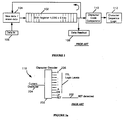
- FIGURE 1 a traditional system used for detection and processing of an end of line character sequence in a 1960's era digital typesetting system is shown.
- a shift register recirculating memory 102 contains a sequence of 6-bit characters in the order to be processed, with a module 104 controlling input 106 of new characters to the sequence as well as the deletion of characters already present in the sequence in the recirculating path.
- the data circulate continually, at the rate of one character per clock cycle moved past a data readout module 108 and a character code comparator module 110 .
- the character code comparator 110 uses digital logic to compare the current data character code with each of a stored set of codes, and to activate processing logic 112 for any match obtained.
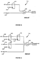
- FIGURE 2a a detail of the character code comparator logic 110 of FIGURE 1 is shown.
- a character decoder 202 examines each current character 204 , and decodes the electrical signal representing the bits making up the character (6 bits in the example), comparing them with the equivalent signal patterns representing all characters 206 of interest to the system.
- a match for any of the characters 206 causes the corresponding logic level to be set to "true".
- the "true" state is herein taken to be a "high” voltage level.
- Logic values conforming to these rules are shown symbolically as an uppercase name without a trailing underscore if they are “true” when "high”. Those with an uppercase name followed by a trailing underscore are “true” when "low”.
- RET return character
- RET detected the return character
- FIGURE 2c the logic of FIGURE 2b is extended to a three-character sequence corresponding to the end of a paragraph: return - line feed - "EM" space.
- the return detected signal 208 is saved for one clock cycle 222 in flip flop 220 and the next in flip flop 240 .
- the line feed character detected in the following clock cycle 242 is saved in flip flop 244 .
- the EM character detected 246 signal is AND'ed with "RET”, delayed by 2 clock cyles and "LF”, delalyed by 1 clock cycle using AND gate 248 . If all three signals are high (true), then the paragraph end detected condition 250 is set.
- an originating data source creates a program such as a PostScript program defined previously, describing a document made up of page descriptions and / or images, and possibly containing PostScript comments to be used purely for information purposes and/ or to be used to describe the structure of the document.
- the PostScript program is transferred to a processing system 300 , in which the incoming data 310 is first received by an input/output processor 312 , passed to a spooler / print manager module 314 , and then processed by a Raster Image Processor (RIP) 318 and output as rasterized data 320 to a raster output device 322 such as an imagesetter or film recorder.
- RIP Raster Image Processor
- the modules making up the embodiment of the invention are located in the data transfer path between the input buffer 342 and the disk writing buffer 346 in such a manner that all data passing along this path can be monitored by a Bit Pattern Decoder 350 which captures the electrical signal corresponding to the sequence of data bits representing each successive ASCII character making up the data stream.
- This decoder 350 is a logic circuit which provides a unique output for each possible input code value.
- a pattern decode corresponding to detection of characters making up any of the sequences to be detected causes a 4-bit status register 354 to be set with an appropriate value.
- the high order bit (bit 4) of this register is always set if the current character being processed is an initial "%" (possibly indicating the beginning of a sequence "%%", “%! or "%?") and reset otherwise.
- the status register 354 contains values to be interpreted as follows:
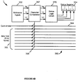
- FIGURE 4a shows a more detailed view of the Bit Pattern Deceder 350 of FIGURE 3 in schematic form.
- the central data path 360 employed within the RIP data system contains 9 lines, of which 8 are used as data lines 362 , and the ninth as a control line 364 .
- the control line 364 represents the appropriate decode of address and control signals.
- data path refers to data, control and address lines.
- the control line 364 is low (logical 0) during transfers on the bus for which no monitoring, is to take place, and high (logical 1) when monitoring is to take place.
- the signal decoder 366 is constantly reading all nine lines, but takes no action unless the control line 364 is high. Decoder 366 decedes an indication of "%", "!, or "?” that is processed by a status logic circuit 370 to set one or more of the 4 bits of the status register 354 as follows:
- FIGURE 5 shows a detail of the digital logic circuitry 350 which implements the Signal Decoder 366 , the Status Logic Circuit 370 , and the status register 354 of FIGURE 4 .
- the combined system bus 510 is made up of the 8-line data bus 362 , an address bus 512 and a control bus 514 controlling many functions, including those related to the invention.
- the high-order address bit (of the 24-bit address word) is used as the control line 364 of FIGURE 4 , effectively creating a pseudo "address-space" for data which is to be monitored by the invention mirroring that of data which is to be transferred without monitoring.
- the comment control module 520 uses the control and address bus lines to generate the signals COMPAR_ 522 , RDFLG_ 524 amd CLRFLG_ 526 to be used as described below.
- the signal PREVIOUS% 536 appearing at the readout buffer 580 is true if the previous character was "%" and false otherwise. Therefore, if the RDFLAG_ signal 524 is given at the end of the last character transferred, Bit 4 will be found to be set only if the last character was a "%" character.
- the other bits, controlled by flip flops 552 , 562 and 572 retain their output signals during the entire transfer process, ensuring that each bit is set independently and retained if at least one occurrence of the corresponding sequence has been detected.
- the flip flops 552 , 562 and 572 are reset by the CLRFLG_ signal 526 , which is issued by the control logic 520 at the beginning of the next transfer.
- the flip flop 532 representing Bit 4 is not reset by CLRFLG_ signal 526 , however, thus allowing the search to continue in the next block transfer.
- the processor After completion of the transfer, the processor must first examine the status register 354 (box 620 ), and check to see if any of the bits 1, 2, or 3 are set corresponding to the conditions previously described (test 624 ). If any are set, then at least one of the indicated sequences has been detected (box 630 ), and the entire buffer must be scanned, character by character, to determine the context within which the sequence(s) have been detected (box 640 ). As a result of this scan, the sequences may indicate valid document structuring comments, coincidental occurrences in another context, or syntax errors. If valid, the operations indicated by the comments are carried out (box 650 ). After this processing, the temporary buffer 346 is transferred to the disk write buffer 347, and setup for the next transfer accomplished (box 660 ).
- the processing software is not required to examine bit 4 of status register 354 , since the condition flagged by that bit, a "%" as the last character of the buffer, is only significant in the processing of the following buffer.
- bits 1,2 or 3 will be set when the loop operates on that buffer. This is true for the PostScript example described above in connection with the preferred embodiment.
- the validity of a byte sequence to be detected may depend upon its context within the data preceding the sequence as well as following it.
- the improvement factor I for the preferred embodiment is shown as a function of the relative number of blocks (data Segments transferred at once) containing at least one structured comment sequence.
- the factor I is obtained according to the following equation: where: t1 and t2 are the transfer times per data block with and without using the method of the invention respectively, t s is the time required for a character-by-character scan of a block of data for comments (in software), N B is the number of blocks for which a comment or coincidental occurrence is detected according to the method, and N T is the total number of blocks transferred.
- the times t1 and t2 are essentially equal.
- the size of the data blocks transferred are in excess of 65,536 Bytes as indicated previously, to ensure that "non-comment" character sequences are not hidden in PostScript strings which are contained in or span data blocks. Accordingly, it can be assumed that t s is much greater than t1 or t2 , with the result that equation [1] reduces to:
- the form shown in FIGURE 7 corresponds to the inverse relationship of equation [2].
Landscapes
- Engineering & Computer Science (AREA)
- Theoretical Computer Science (AREA)
- Physics & Mathematics (AREA)
- General Physics & Mathematics (AREA)
- General Engineering & Computer Science (AREA)
- Human Computer Interaction (AREA)
- Computational Mathematics (AREA)
- Mathematical Analysis (AREA)
- Mathematical Optimization (AREA)
- Pure & Applied Mathematics (AREA)
- Compression, Expansion, Code Conversion, And Decoders (AREA)
- Communication Control (AREA)
Applications Claiming Priority (2)
| Application Number | Priority Date | Filing Date | Title |
|---|---|---|---|
| US96095392A | 1992-10-14 | 1992-10-14 | |
| US960953 | 1997-10-30 |
Publications (2)
| Publication Number | Publication Date |
|---|---|
| EP0601304A1 true EP0601304A1 (de) | 1994-06-15 |
| EP0601304B1 EP0601304B1 (de) | 1999-01-27 |
Family
ID=25503868
Family Applications (1)
| Application Number | Title | Priority Date | Filing Date |
|---|---|---|---|
| EP19930116507 Expired - Lifetime EP0601304B1 (de) | 1992-10-14 | 1993-10-12 | Verfahren und Anordnung zur Erkennung von Bit-Sequenzen in Datenströmen |
Country Status (2)
| Country | Link |
|---|---|
| EP (1) | EP0601304B1 (de) |
| DE (1) | DE69323283T2 (de) |
Cited By (11)
| Publication number | Priority date | Publication date | Assignee | Title |
|---|---|---|---|---|
| FR2723457A1 (fr) * | 1994-08-08 | 1996-02-09 | Oce Graphics France | Procede de reconnaissance automatique d'un langage dans lequel des donnees numeriques sont recues |
| WO1997006481A1 (en) * | 1995-08-07 | 1997-02-20 | T/R Systems | Virtual single printer engine with software rip |
| GB2330993A (en) * | 1997-10-30 | 1999-05-05 | Advanced Micro Devices Inc | Detecting a prescribed pattern in a data stream by selectively skipping groups of non-relevant data bytes |
| US5940186A (en) * | 1994-01-13 | 1999-08-17 | T/R Systems, Inc. | Multiple printer module electrophotographic printing device |
| US6035103A (en) * | 1995-08-07 | 2000-03-07 | T/R Systems | Color correction for multiple print engine system with half tone and bi-level printing |
| DE10159911A1 (de) * | 2001-12-06 | 2003-06-26 | Rohde & Schwarz | Verfahren zur gezielten Annahme von Datenabschnitten |
| US6707563B1 (en) | 1999-01-11 | 2004-03-16 | T/R Systems | Multiple print engine with error handling capability |
| US6850335B1 (en) | 1996-08-16 | 2005-02-01 | Electronics For Imaging, Inc. | Method and apparatus for distributing pages to individual print engines in a multiple print engine |
| US6977752B1 (en) | 1995-08-07 | 2005-12-20 | Electronics For Imaging, Inc. | Method and apparatus for determining toner level in electrophotographic print engines |
| US7027187B1 (en) | 1995-08-07 | 2006-04-11 | Electronics For Imaging, Inc. | Real time calibration of a marking engine in a print system |
| US7046391B1 (en) | 1995-08-07 | 2006-05-16 | Electronics For Imaging, Inc. | Method and apparatus for providing a color-balanced multiple print engine |
Citations (4)
| Publication number | Priority date | Publication date | Assignee | Title |
|---|---|---|---|---|
| EP0223458A2 (de) * | 1985-11-14 | 1987-05-27 | Hewlett-Packard Company | Maschine zur mehrfachen Filterung |
| EP0408936A2 (de) * | 1989-07-18 | 1991-01-23 | Wandel & Goltermann Gmbh & Co | Verfahren zum Auffinden eines Zeichenmusters in einem Datenstrom |
| EP0469974A2 (de) * | 1990-08-03 | 1992-02-05 | Qms, Inc. | Drucker, der verschiedene Druckersteuerungssprachen auswertet |
| WO1992004672A1 (en) * | 1990-09-12 | 1992-03-19 | Hewlett-Packard Company | Method and system for matching the software command language of a computer with the printer language of a printer |
-
1993
- 1993-10-12 DE DE1993623283 patent/DE69323283T2/de not_active Expired - Fee Related
- 1993-10-12 EP EP19930116507 patent/EP0601304B1/de not_active Expired - Lifetime
Patent Citations (4)
| Publication number | Priority date | Publication date | Assignee | Title |
|---|---|---|---|---|
| EP0223458A2 (de) * | 1985-11-14 | 1987-05-27 | Hewlett-Packard Company | Maschine zur mehrfachen Filterung |
| EP0408936A2 (de) * | 1989-07-18 | 1991-01-23 | Wandel & Goltermann Gmbh & Co | Verfahren zum Auffinden eines Zeichenmusters in einem Datenstrom |
| EP0469974A2 (de) * | 1990-08-03 | 1992-02-05 | Qms, Inc. | Drucker, der verschiedene Druckersteuerungssprachen auswertet |
| WO1992004672A1 (en) * | 1990-09-12 | 1992-03-19 | Hewlett-Packard Company | Method and system for matching the software command language of a computer with the printer language of a printer |
Cited By (31)
| Publication number | Priority date | Publication date | Assignee | Title |
|---|---|---|---|---|
| US5940186A (en) * | 1994-01-13 | 1999-08-17 | T/R Systems, Inc. | Multiple printer module electrophotographic printing device |
| EP0702289A1 (de) * | 1994-08-08 | 1996-03-20 | Océ-Nederland B.V. | Verfahren zur automatischen Erkennung einer Sprache, in der digitale Daten empfangen werden |
| FR2723457A1 (fr) * | 1994-08-08 | 1996-02-09 | Oce Graphics France | Procede de reconnaissance automatique d'un langage dans lequel des donnees numeriques sont recues |
| US5960113A (en) * | 1994-08-08 | 1999-09-28 | Oce-Nederland, B.V. | Method of automatically recognizing a language in which digital data is received |
| US7116444B2 (en) | 1995-08-07 | 2006-10-03 | Electronics For Imaging, Inc. | Method and apparatus for determining toner level in electrophotographic print engines |
| US7301671B2 (en) | 1995-08-07 | 2007-11-27 | Electronics For Imaging, Inc. | Method for calibrating a color marking engine for halftone operation |
| US7791777B2 (en) | 1995-08-07 | 2010-09-07 | Electronics For Imaging, Inc. | Method and apparatus for providing a color-balanced multiple print engine |
| US6035103A (en) * | 1995-08-07 | 2000-03-07 | T/R Systems | Color correction for multiple print engine system with half tone and bi-level printing |
| US6219155B1 (en) | 1995-08-07 | 2001-04-17 | T/R Systems | Color correction of contone images in a multiple print engine system |
| US6271937B1 (en) | 1995-08-07 | 2001-08-07 | Peter A. Zuber | Color correction of dot linearities in multiple print engine system |
| US7532347B2 (en) | 1995-08-07 | 2009-05-12 | Electronics For Imaging, Inc. | Methods and apparatus for routing pages to printers in a multi-print engine as a function of print job parameters |
| US6606165B1 (en) | 1995-08-07 | 2003-08-12 | T/R Systems, Inc. | Method and apparatus for routing pages to printers in a multi-print engine as a function of print job parameters |
| US6636326B1 (en) | 1995-08-07 | 2003-10-21 | T/R Systems | Method for calibrating a color marking engine for halftone operation |
| US6657741B1 (en) | 1995-08-07 | 2003-12-02 | Tr Systems, Inc. | Multiple print engine system with selectively distributed ripped pages |
| US7489422B2 (en) | 1995-08-07 | 2009-02-10 | Electronics For Imaging, Inc. | Methods and apparatus for real time calibration of a print system marking engine |
| US7471403B2 (en) | 1995-08-07 | 2008-12-30 | Electronics For Imaging, Inc. | Apparatus and methods for selectively distributing print pages in multiple print engine systems |
| US6977752B1 (en) | 1995-08-07 | 2005-12-20 | Electronics For Imaging, Inc. | Method and apparatus for determining toner level in electrophotographic print engines |
| US7349124B2 (en) | 1995-08-07 | 2008-03-25 | Electronics For Imaging, Inc. | Methods and apparatus for real time calibration of a marking engine in a print system |
| US7027187B1 (en) | 1995-08-07 | 2006-04-11 | Electronics For Imaging, Inc. | Real time calibration of a marking engine in a print system |
| US7046391B1 (en) | 1995-08-07 | 2006-05-16 | Electronics For Imaging, Inc. | Method and apparatus for providing a color-balanced multiple print engine |
| US7095528B2 (en) | 1995-08-07 | 2006-08-22 | Electronics For Imaging, Inc. | Apparatus and methods for duplex printing in multiple print engine systems |
| WO1997006481A1 (en) * | 1995-08-07 | 1997-02-20 | T/R Systems | Virtual single printer engine with software rip |
| US7206082B2 (en) | 1995-08-07 | 2007-04-17 | Electronics For Imaging, Inc. | Method and apparatus for routing pages to printers in a multi-print engine as a function of print job parameters |
| US7342686B2 (en) | 1995-08-07 | 2008-03-11 | Electronics For Imaging, Inc. | Method and apparatus for providing a color-balanced multiple print engine |
| US7301665B2 (en) | 1995-08-07 | 2007-11-27 | Electronics For Imaging, Inc. | Method and apparatus for determining toner level in electrophotographic print engines |
| US6850335B1 (en) | 1996-08-16 | 2005-02-01 | Electronics For Imaging, Inc. | Method and apparatus for distributing pages to individual print engines in a multiple print engine |
| GB2330993B (en) * | 1997-10-30 | 1999-09-15 | Advanced Micro Devices Inc | Apparatus and method for detecting a prescribed pattern in a data stream by selectively skipping groups of non-relevant data bytes |
| GB2330993A (en) * | 1997-10-30 | 1999-05-05 | Advanced Micro Devices Inc | Detecting a prescribed pattern in a data stream by selectively skipping groups of non-relevant data bytes |
| US6707563B1 (en) | 1999-01-11 | 2004-03-16 | T/R Systems | Multiple print engine with error handling capability |
| DE10159911B4 (de) * | 2001-12-06 | 2005-12-22 | Rohde & Schwarz Gmbh & Co. Kg | Verfahren zur gezielten Annahme von Datenabschnitten |
| DE10159911A1 (de) * | 2001-12-06 | 2003-06-26 | Rohde & Schwarz | Verfahren zur gezielten Annahme von Datenabschnitten |
Also Published As
| Publication number | Publication date |
|---|---|
| DE69323283D1 (de) | 1999-03-11 |
| EP0601304B1 (de) | 1999-01-27 |
| DE69323283T2 (de) | 1999-08-12 |
Similar Documents
| Publication | Publication Date | Title |
|---|---|---|
| US4594674A (en) | Generating and storing electronic fonts | |
| US5051886A (en) | System for character stream search using finite state automaton technique | |
| US4079458A (en) | High resolution character generator | |
| US4539653A (en) | Formatting text/graphics using plural independent formatting mechanisms | |
| US4745561A (en) | Character font pattern editing system for modification of font patterns | |
| EP0601304B1 (de) | Verfahren und Anordnung zur Erkennung von Bit-Sequenzen in Datenströmen | |
| US5960113A (en) | Method of automatically recognizing a language in which digital data is received | |
| JPH05334024A (ja) | データ・ストリーム言語を自動的に判定するプリンタ | |
| US4007442A (en) | Intermixed line heights and blank line formation in a buffered printer | |
| US4393463A (en) | Insertion of character set change codes in an altered text stream | |
| US5673209A (en) | Apparatus and associated method for compressing and decompressing digital data | |
| JPH029656A (ja) | フォントの含蓄方法 | |
| EP0077892B1 (de) | Wortverarbeitendes System mit einem formatierenden bidirektionalen Drucker | |
| CA1113188A (en) | Text processing apparatus | |
| US4717911A (en) | Technique for chaining lines of a document together to facilitate editing or proofreading | |
| US4040024A (en) | Editing system for a random access memory | |
| US7002581B2 (en) | Character information processing apparatus, character information processing method and storage medium | |
| EP0119396B1 (de) | Einrichtung und Verfahren zur Darstellung oder Anzeige von durch elektrische Signale dargestellte Daten | |
| US20010016068A1 (en) | Electronic document generating apparatus, electronic document generating method, and program thereof | |
| US3755784A (en) | System for revision line retrieval | |
| US4794389A (en) | Attribute hierarchy system | |
| US4402058A (en) | Keyboard mismatch correction | |
| EP0052711B1 (de) | Verfahren in einem Textverarbeitungssystem zur Textverarbeitung mit Einfügung eines Textblockes | |
| US4689764A (en) | Method and apparatus for formatting a line of text containing a complex character prior to text justification | |
| US6775024B1 (en) | Method for selectively detecting and reading a character string |
Legal Events
| Date | Code | Title | Description |
|---|---|---|---|
| PUAI | Public reference made under article 153(3) epc to a published international application that has entered the european phase |
Free format text: ORIGINAL CODE: 0009012 |
|
| AK | Designated contracting states |
Kind code of ref document: A1 Designated state(s): BE DE FR GB |
|
| 17P | Request for examination filed |
Effective date: 19941212 |
|
| RAP1 | Party data changed (applicant data changed or rights of an application transferred) |
Owner name: BAYER CORPORATION |
|
| 17Q | First examination report despatched |
Effective date: 19970617 |
|
| GRAG | Despatch of communication of intention to grant |
Free format text: ORIGINAL CODE: EPIDOS AGRA |
|
| GRAG | Despatch of communication of intention to grant |
Free format text: ORIGINAL CODE: EPIDOS AGRA |
|
| GRAH | Despatch of communication of intention to grant a patent |
Free format text: ORIGINAL CODE: EPIDOS IGRA |
|
| GRAH | Despatch of communication of intention to grant a patent |
Free format text: ORIGINAL CODE: EPIDOS IGRA |
|
| GRAA | (expected) grant |
Free format text: ORIGINAL CODE: 0009210 |
|
| AK | Designated contracting states |
Kind code of ref document: B1 Designated state(s): BE DE FR GB |
|
| PG25 | Lapsed in a contracting state [announced via postgrant information from national office to epo] |
Ref country code: BE Free format text: LAPSE BECAUSE OF FAILURE TO SUBMIT A TRANSLATION OF THE DESCRIPTION OR TO PAY THE FEE WITHIN THE PRESCRIBED TIME-LIMIT Effective date: 19990127 |
|
| ET | Fr: translation filed | ||
| REF | Corresponds to: |
Ref document number: 69323283 Country of ref document: DE Date of ref document: 19990311 |
|
| RAP2 | Party data changed (patent owner data changed or rights of a patent transferred) |
Owner name: AGFA CORPORATION |
|
| PLBE | No opposition filed within time limit |
Free format text: ORIGINAL CODE: 0009261 |
|
| STAA | Information on the status of an ep patent application or granted ep patent |
Free format text: STATUS: NO OPPOSITION FILED WITHIN TIME LIMIT |
|
| 26N | No opposition filed | ||
| PGFP | Annual fee paid to national office [announced via postgrant information from national office to epo] |
Ref country code: FR Payment date: 20001017 Year of fee payment: 8 |
|
| PGFP | Annual fee paid to national office [announced via postgrant information from national office to epo] |
Ref country code: GB Payment date: 20001030 Year of fee payment: 8 |
|
| PGFP | Annual fee paid to national office [announced via postgrant information from national office to epo] |
Ref country code: DE Payment date: 20001229 Year of fee payment: 8 |
|
| PG25 | Lapsed in a contracting state [announced via postgrant information from national office to epo] |
Ref country code: GB Free format text: LAPSE BECAUSE OF NON-PAYMENT OF DUE FEES Effective date: 20011012 |
|
| REG | Reference to a national code |
Ref country code: GB Ref legal event code: IF02 |
|
| GBPC | Gb: european patent ceased through non-payment of renewal fee |
Effective date: 20011012 |
|
| PG25 | Lapsed in a contracting state [announced via postgrant information from national office to epo] |
Ref country code: FR Free format text: LAPSE BECAUSE OF NON-PAYMENT OF DUE FEES Effective date: 20020628 |
|
| PG25 | Lapsed in a contracting state [announced via postgrant information from national office to epo] |
Ref country code: DE Free format text: LAPSE BECAUSE OF NON-PAYMENT OF DUE FEES Effective date: 20020702 |
|
| REG | Reference to a national code |
Ref country code: FR Ref legal event code: ST |