EP0601313A2 - Dispositif pour la microchirurgie de l'oeil d'un être vivant - Google Patents
Dispositif pour la microchirurgie de l'oeil d'un être vivant Download PDFInfo
- Publication number
- EP0601313A2 EP0601313A2 EP93116916A EP93116916A EP0601313A2 EP 0601313 A2 EP0601313 A2 EP 0601313A2 EP 93116916 A EP93116916 A EP 93116916A EP 93116916 A EP93116916 A EP 93116916A EP 0601313 A2 EP0601313 A2 EP 0601313A2
- Authority
- EP
- European Patent Office
- Prior art keywords
- hose line
- support part
- unit
- chamber
- intermediate wall
- Prior art date
- Legal status (The legal status is an assumption and is not a legal conclusion. Google has not performed a legal analysis and makes no representation as to the accuracy of the status listed.)
- Granted
Links
Images




Classifications
-
- A—HUMAN NECESSITIES
- A61—MEDICAL OR VETERINARY SCIENCE; HYGIENE
- A61M—DEVICES FOR INTRODUCING MEDIA INTO, OR ONTO, THE BODY; DEVICES FOR TRANSDUCING BODY MEDIA OR FOR TAKING MEDIA FROM THE BODY; DEVICES FOR PRODUCING OR ENDING SLEEP OR STUPOR
- A61M3/00—Medical syringes, e.g. enemata; Irrigators
- A61M3/02—Enemata; Irrigators
- A61M3/0233—Enemata; Irrigators characterised by liquid supply means, e.g. from pressurised reservoirs
-
- A—HUMAN NECESSITIES
- A61—MEDICAL OR VETERINARY SCIENCE; HYGIENE
- A61M—DEVICES FOR INTRODUCING MEDIA INTO, OR ONTO, THE BODY; DEVICES FOR TRANSDUCING BODY MEDIA OR FOR TAKING MEDIA FROM THE BODY; DEVICES FOR PRODUCING OR ENDING SLEEP OR STUPOR
- A61M1/00—Suction or pumping devices for medical purposes; Devices for carrying-off, for treatment of, or for carrying-over, body-liquids; Drainage systems
- A61M1/71—Suction drainage systems
- A61M1/72—Cassettes forming partially or totally the fluid circuit
-
- A—HUMAN NECESSITIES
- A61—MEDICAL OR VETERINARY SCIENCE; HYGIENE
- A61M—DEVICES FOR INTRODUCING MEDIA INTO, OR ONTO, THE BODY; DEVICES FOR TRANSDUCING BODY MEDIA OR FOR TAKING MEDIA FROM THE BODY; DEVICES FOR PRODUCING OR ENDING SLEEP OR STUPOR
- A61M1/00—Suction or pumping devices for medical purposes; Devices for carrying-off, for treatment of, or for carrying-over, body-liquids; Drainage systems
- A61M1/71—Suction drainage systems
- A61M1/77—Suction-irrigation systems
-
- A—HUMAN NECESSITIES
- A61—MEDICAL OR VETERINARY SCIENCE; HYGIENE
- A61M—DEVICES FOR INTRODUCING MEDIA INTO, OR ONTO, THE BODY; DEVICES FOR TRANSDUCING BODY MEDIA OR FOR TAKING MEDIA FROM THE BODY; DEVICES FOR PRODUCING OR ENDING SLEEP OR STUPOR
- A61M3/00—Medical syringes, e.g. enemata; Irrigators
- A61M3/02—Enemata; Irrigators
- A61M3/0201—Cassettes therefor
-
- E—FIXED CONSTRUCTIONS
- E05—LOCKS; KEYS; WINDOW OR DOOR FITTINGS; SAFES
- E05C—BOLTS OR FASTENING DEVICES FOR WINGS, SPECIALLY FOR DOORS OR WINDOWS
- E05C19/00—Other devices specially designed for securing wings, e.g. with suction cups
- E05C19/02—Automatic catches, i.e. released by pull or pressure on the wing
- E05C19/024—Automatic catches, i.e. released by pull or pressure on the wing with a bifurcated latch
-
- A—HUMAN NECESSITIES
- A61—MEDICAL OR VETERINARY SCIENCE; HYGIENE
- A61F—FILTERS IMPLANTABLE INTO BLOOD VESSELS; PROSTHESES; DEVICES PROVIDING PATENCY TO, OR PREVENTING COLLAPSING OF, TUBULAR STRUCTURES OF THE BODY, e.g. STENTS; ORTHOPAEDIC, NURSING OR CONTRACEPTIVE DEVICES; FOMENTATION; TREATMENT OR PROTECTION OF EYES OR EARS; BANDAGES, DRESSINGS OR ABSORBENT PADS; FIRST-AID KITS
- A61F9/00—Methods or devices for treatment of the eyes; Devices for putting in contact-lenses; Devices to correct squinting; Apparatus to guide the blind; Protective devices for the eyes, carried on the body or in the hand
- A61F9/007—Methods or devices for eye surgery
- A61F9/00736—Instruments for removal of intra-ocular material or intra-ocular injection, e.g. cataract instruments
-
- A—HUMAN NECESSITIES
- A61—MEDICAL OR VETERINARY SCIENCE; HYGIENE
- A61M—DEVICES FOR INTRODUCING MEDIA INTO, OR ONTO, THE BODY; DEVICES FOR TRANSDUCING BODY MEDIA OR FOR TAKING MEDIA FROM THE BODY; DEVICES FOR PRODUCING OR ENDING SLEEP OR STUPOR
- A61M1/00—Suction or pumping devices for medical purposes; Devices for carrying-off, for treatment of, or for carrying-over, body-liquids; Drainage systems
- A61M1/71—Suction drainage systems
- A61M1/74—Suction control
-
- A—HUMAN NECESSITIES
- A61—MEDICAL OR VETERINARY SCIENCE; HYGIENE
- A61M—DEVICES FOR INTRODUCING MEDIA INTO, OR ONTO, THE BODY; DEVICES FOR TRANSDUCING BODY MEDIA OR FOR TAKING MEDIA FROM THE BODY; DEVICES FOR PRODUCING OR ENDING SLEEP OR STUPOR
- A61M1/00—Suction or pumping devices for medical purposes; Devices for carrying-off, for treatment of, or for carrying-over, body-liquids; Drainage systems
- A61M1/71—Suction drainage systems
- A61M1/74—Suction control
- A61M1/741—Suction control with means for varying suction manually
- A61M1/7411—Suction control with means for varying suction manually by changing the size of a vent
-
- A—HUMAN NECESSITIES
- A61—MEDICAL OR VETERINARY SCIENCE; HYGIENE
- A61M—DEVICES FOR INTRODUCING MEDIA INTO, OR ONTO, THE BODY; DEVICES FOR TRANSDUCING BODY MEDIA OR FOR TAKING MEDIA FROM THE BODY; DEVICES FOR PRODUCING OR ENDING SLEEP OR STUPOR
- A61M2202/00—Special media to be introduced, removed or treated
- A61M2202/02—Gases
-
- A—HUMAN NECESSITIES
- A61—MEDICAL OR VETERINARY SCIENCE; HYGIENE
- A61M—DEVICES FOR INTRODUCING MEDIA INTO, OR ONTO, THE BODY; DEVICES FOR TRANSDUCING BODY MEDIA OR FOR TAKING MEDIA FROM THE BODY; DEVICES FOR PRODUCING OR ENDING SLEEP OR STUPOR
- A61M2202/00—Special media to be introduced, removed or treated
- A61M2202/04—Liquids
-
- A—HUMAN NECESSITIES
- A61—MEDICAL OR VETERINARY SCIENCE; HYGIENE
- A61M—DEVICES FOR INTRODUCING MEDIA INTO, OR ONTO, THE BODY; DEVICES FOR TRANSDUCING BODY MEDIA OR FOR TAKING MEDIA FROM THE BODY; DEVICES FOR PRODUCING OR ENDING SLEEP OR STUPOR
- A61M2205/00—General characteristics of the apparatus
- A61M2205/12—General characteristics of the apparatus with interchangeable cassettes forming partially or totally the fluid circuit
-
- A—HUMAN NECESSITIES
- A61—MEDICAL OR VETERINARY SCIENCE; HYGIENE
- A61M—DEVICES FOR INTRODUCING MEDIA INTO, OR ONTO, THE BODY; DEVICES FOR TRANSDUCING BODY MEDIA OR FOR TAKING MEDIA FROM THE BODY; DEVICES FOR PRODUCING OR ENDING SLEEP OR STUPOR
- A61M2210/00—Anatomical parts of the body
- A61M2210/06—Head
- A61M2210/0612—Eyes
-
- A—HUMAN NECESSITIES
- A61—MEDICAL OR VETERINARY SCIENCE; HYGIENE
- A61M—DEVICES FOR INTRODUCING MEDIA INTO, OR ONTO, THE BODY; DEVICES FOR TRANSDUCING BODY MEDIA OR FOR TAKING MEDIA FROM THE BODY; DEVICES FOR PRODUCING OR ENDING SLEEP OR STUPOR
- A61M3/00—Medical syringes, e.g. enemata; Irrigators
- A61M3/02—Enemata; Irrigators
- A61M3/0204—Physical characteristics of the irrigation fluid, e.g. conductivity or turbidity
- A61M3/0208—Physical characteristics of the irrigation fluid, e.g. conductivity or turbidity before use
-
- A—HUMAN NECESSITIES
- A61—MEDICAL OR VETERINARY SCIENCE; HYGIENE
- A61M—DEVICES FOR INTRODUCING MEDIA INTO, OR ONTO, THE BODY; DEVICES FOR TRANSDUCING BODY MEDIA OR FOR TAKING MEDIA FROM THE BODY; DEVICES FOR PRODUCING OR ENDING SLEEP OR STUPOR
- A61M3/00—Medical syringes, e.g. enemata; Irrigators
- A61M3/02—Enemata; Irrigators
- A61M3/0204—Physical characteristics of the irrigation fluid, e.g. conductivity or turbidity
- A61M3/0212—Physical characteristics of the irrigation fluid, e.g. conductivity or turbidity after use
-
- A—HUMAN NECESSITIES
- A61—MEDICAL OR VETERINARY SCIENCE; HYGIENE
- A61M—DEVICES FOR INTRODUCING MEDIA INTO, OR ONTO, THE BODY; DEVICES FOR TRANSDUCING BODY MEDIA OR FOR TAKING MEDIA FROM THE BODY; DEVICES FOR PRODUCING OR ENDING SLEEP OR STUPOR
- A61M3/00—Medical syringes, e.g. enemata; Irrigators
- A61M3/02—Enemata; Irrigators
- A61M3/0204—Physical characteristics of the irrigation fluid, e.g. conductivity or turbidity
- A61M3/0216—Pressure
-
- A—HUMAN NECESSITIES
- A61—MEDICAL OR VETERINARY SCIENCE; HYGIENE
- A61M—DEVICES FOR INTRODUCING MEDIA INTO, OR ONTO, THE BODY; DEVICES FOR TRANSDUCING BODY MEDIA OR FOR TAKING MEDIA FROM THE BODY; DEVICES FOR PRODUCING OR ENDING SLEEP OR STUPOR
- A61M3/00—Medical syringes, e.g. enemata; Irrigators
- A61M3/02—Enemata; Irrigators
- A61M3/0204—Physical characteristics of the irrigation fluid, e.g. conductivity or turbidity
- A61M3/022—Volume; Flow rate
Definitions
- the invention relates to a device for microsurgical interventions on the eye of a living being, comprising a housing, an irrigation unit connected to a first hose line, an aspiration unit connected to a second hose line, a pump unit and an exchangeable unit for accommodating the two Hose lines designed carrier unit, wherein the carrier unit is connected to the pump unit in the assembled state such that a pump wheel rotatably driven about an axis interacts with the second hose line peristaltically via at least one roller rotatably mounted thereon.
- a device which comprises a microsurgical irrigation and aspiration system which interacts with a pump unit, in which system a tube carrier designed as a cassette is arranged essentially on a front plate of a carrier element designed as a housing and can be pivoted by means of a is held on the front panel locking element.
- the hose carrier provided with a first and a second hose line has a substantially semicircular recess for receiving a pump unit, the pump unit having a pump wheel rotatably driven about an axis and rollers rotatably mounted thereon, which interacts with the hose line of the aspiration unit peristaltically when the hose carrier is in the assembled state.
- the invention is based on the object, on the one hand, of creating a support unit for the hose lines for a device of the type mentioned at the beginning and, on the other hand, of specifying a device with which the insertion of the support unit is made considerably easier and an exact interaction of the corresponding hose line with the pump unit is achieved.
- the invention solves the problem by means of an insertable element as a carrier unit which can be inserted into a chamber, the insert element having a first support part for the first hose line and a second support part arranged transversely to the insertion direction for the second hose line and at least one latching cam which is inserted when the Insert element in the chamber cooperates with a retracting and locking mechanism arranged therein that in the retracted end position of the insert element, the first hose line can be brought into engagement with an interrupter element and the second hose line with the rollers of the pump wheel driven by a drive unit.
- the device 100 comprises a plurality of functional units 3, 4, 10, 12 and 14 arranged in a housing 1 and designed for the respective operative intervention.
- the individual functional units 3, 4, 10, 12 and 14 are preferably interchangeable inserts, not shown trained and insertable from the front into the housing 1.
- the first two functional units 3 and 4 are provided with means, not shown, by means of which the interior of the eye can be illuminated during the surgical intervention.
- an optical fiber cable (not shown), which is provided at one end with a light source and at the other end with a connecting part, is connected to the correspondingly configured sockets 3 ′′ and / or 4 ′′ of the functional units 3 and / or 4.
- the luminous intensity required for the surgical intervention can be infinitely adjusted and regulated using a rotary knob 3 'and / or 4'.
- a connector strip 7 which is provided with a plurality of connections on the end face of the housing 1 and which is provided for the connection of additional surgical instruments or the like, not shown in detail.
- an image field 2 is arranged above the individual functional units, which is subdivided, for example, into individual display and operating fields 2 'with an LCD display (liquid crystal display).
- the individual display and control panel 2 ' serves as a program-dependent controlled exchange of information for the user of the entire ophthalmic device 100.
- the individual display and control panels 2' can be actuated by slight finger pressure for the respective program selection, the selected display or selected displays in relation to the non-actuated displays are then illuminated.
- the first functional unit 10 is referred to as an irrigation unit 10 and the second functional unit 12 as an aspiration unit 12.
- the third functional unit 14 is referred to as a printing unit 14.
- the two units 10 and 12 are connected to one another via supply and disposal lines (not shown) and together form an aspiration and irrigation system (not shown).
- the pressure unit 14 has at least one connecting piece 6 for connecting a line and an adjusting button 5 for regulating the intraocular pressure (IOP) during the surgical procedure.
- the pressure unit 14 can be assigned a viscous injection device (not shown in more detail), which has a connecting piece 6 'for connecting a line (not shown) and an adjusting button 5' for regulating.
- the individual functional elements of the irrigation unit 10 and of the aspiration unit 12, which are not shown in more detail in FIG. 1, are operatively connected to one another via a slide-in element 30 which is shown schematically in FIG. 1 and can be pushed into the housing 1 of the device 100.
- a slide-in element 30 which is shown schematically in FIG. 1 and can be pushed into the housing 1 of the device 100.
- On the end face of the insert element 30, connecting pieces 8, 8 'and 9, 9' arranged at a distance from one another are provided which the individual supply and disposal lines of the aspiration and irrigation system, not shown, are connected.
- an appropriately designed chamber 24 can be arranged in the housing 1 for accommodating the individual functional elements and for accommodating the insertion element 30.
- a support element 20 which can be inserted into the housing 1 is preferably provided and has the chamber 24 into which the insertion element 30 can be inserted and pulled out again.
- the insertion element 30 designed as a tube carrier can be pulled out according to the direction of arrow Y from a carrier element 20 arranged in the housing 1, not shown here, and pushed back into the chamber 24 of the carrier element 20 in the direction of the arrow Y '.
- a handle 31 can be seen, a plate 18 arranged thereon on the end face with the connecting pieces 8, 8 'and 9, 9' spaced apart therefrom for the supply and disposal lines, not shown.
- the insertion element 30 has a first support part 35 and a second support part 45 as well as a latching cam 40 which is arranged on the side of the second support part 45 facing the first support part 35.
- the two support parts 35 and 45 are designed to hold the individual hoses (FIG. 4.5) of the aspiration and irrigation system, not shown here.
- the structural design of the insert element 30 will be described in detail later in connection with FIGS. 6, 7 and 8.
- a plurality of functional elements are arranged in the carrier element 20, with which the insert element 30 is operatively connected in the inserted state stands.
- the functional elements arranged in different functional levels in the carrier element 20 as well as a correspondingly designed retraction and locking mechanism for the insertion element 30 are described below.
- FIG. 2 shows a section of the carrier element 20 shown on a larger scale and in a sectional view.
- the essentially box-shaped support element 20 has an upper and a lower base plate 21 and 21 ', two side walls 23 and 23' (FIG. 9), an end plate 22 and a rear wall (not shown), the parts 21, 21 'and 23, 23 'and 22 essentially form the chamber 24 designed to accommodate the individual functional elements.
- An opening 22 ′ (FIG. 9) is provided in the end plate 22, through which the insert element 30, for example in the form of a cassette, can be inserted into the chamber 24.
- a first intermediate wall 25 is arranged between the two base plates 21 and 21 'and is fastened in the carrier element 20 by means not shown.
- a drive unit 15 for a pump unit (FIG. 5) is provided on the first intermediate wall 25 with a gear 15 ′′, a drive shaft 16 (FIG. 9) and a drive motor 15 ′. Furthermore, a magnetic valve 17, a ventilation valve 29 and a pressure measuring device 26 connected thereto via a line 27 are arranged on the first intermediate wall 25. A line 28 connected to a connection housing 57 (FIG. 3) is also connected to line 27.
- the functional elements 15, 17, 26 and 29 fastened to the first intermediate wall 25, not shown, by means not shown, together with the first intermediate wall 25 essentially form a first functional level.
- the pressure measuring device 26 is fastened with a holder 26 'to the first intermediate wall 25 and to a second intermediate wall 25' (FIG. 9) arranged at a distance from it.
- FIG. 3 shows the support element 20, shown on a larger scale and in a sectional view, and the insertion element 30, which is partially pulled out of the chamber 24 in the direction of the arrow Y. Furthermore, the second intermediate wall 25 'can be seen, which is also fastened in the support element 20 by means not shown .
- a pull-in and locking mechanism 60 Arranged on the second intermediate wall 25 'is a pull-in and locking mechanism 60 which, in the position shown in FIG. 3, is essentially out of engagement of the locking cam 40 arranged on the insertion element 30.
- the first support part 35 which has a first channel 36 for a first hose line 11 of the irrigation unit 10, is arranged on the insertion element 30.
- connection housing 57 is arranged on the second intermediate wall 25 'and fastened by means not shown.
- the connection housing 57 is formed on one side via the lines 28 and 27 with the pressure measuring device 26 and on the other side for receiving a coupling piece 56 ′ arranged on a filter 56.
- the pressure measuring device 26 is arranged and fastened with the holder 26 ′ on the first and on the second intermediate wall 25, 25 ′.
- the retraction and locking mechanism 60 which is also arranged on the second intermediate wall 25 ', essentially comprises, as shown in FIG. 3, two locking levers which are arranged corresponding to one another and each have one end via a pin 62 and 62' on the second intermediate wall 25 ' 61 and 61 '.
- the two locking levers 61 and 61 ' are pivotally mounted on the second intermediate wall 25' against the restoring force of tension members 69 and 69 'which are operatively connected therewith about the axes of the two pins 62 and 62'.
- the locking cam 40 formed on the second support part 45 is pressed against the one fork parts 64, 64' of the two locking levers 61, 61 '.
- the locking levers 61, 61 ' are pivoted about the two pins 62, 62' and at the same time the two coil springs 69, 69 'about the pins 67, 67'.
- the two coil springs 69, 69 ' are tensioned.
- the latching cam 40 of the insertion element 30 is out of engagement of the two locking levers 61 and 61', so that the insertion element 30 according to the direction of the arrow Y from the chamber 24 of the carrier element 20 or from one not shown chamber of the housing 1 can be pulled out.
- the insertion element 30 with the latching cam 40 is preferably in a slot 125 arranged in the insertion direction in the second intermediate wall 25', on the one hand with respect to the insertion - And locking mechanism 60 and on the other hand out with respect to the pump unit 70.
- the insertion element 30 is brought into exact engagement with the second support part 45 provided with the second hose line 13, as shown in FIG. 5, with the pump unit 70 arranged on a third intermediate wall 25 ′′.
- rollers 71, 71 ′ and stops 72 which are arranged at a distance from one another, can also be provided for guiding the insertion element 30, by means of which tilting of the insertion element 30 in the carrier element 20 is prevented.
- a switch 54 'provided with a sensing element 54' is also attached to the third intermediate wall 25 '' by means not shown. From the switch 54 'provided with a pushbutton 54', a signal is passed on to the pump unit 70 in the end position for operational readiness. The pump unit 70 is actuated by the signal.
- the pump unit 70 which is operatively connected to the drive shaft 16 of the drive unit 15 (FIG. 2) via a drive shaft 83 (FIG. 9) and a coupling 19, comprises, as in FIG 5 shows a pump wheel 80 driven in the direction of the arrow R. Rollers 75 which are arranged at a distance from one another are mounted on the pump wheel 80 in the circumferential direction. In the exemplary embodiment shown, five rollers 75 arranged on the circumference are provided on the pump wheel 80. It is hereby achieved that in each position of the pump wheel 80 at least two rollers 75 are engaged with the second hose line 13 (FIG. 5) arranged on the second support part 45.
- the rollers 75 are each driven about an axis 76 against the direction of rotation of the pump wheel 80 in the direction of the arrow R '.
- the rollers 75 which are driven in the direction of the arrow R 'in the direction of the arrow R of the pump wheel 80, bring about an optimal functioning of the peristaltic pump wheel 80, without a tensile effect extending the hose line 13 being transmitted to the hose line 13, which lies against the circular curved path 50.
- the pump unit 70 arranged on the third intermediate wall 25 ′′ will be described in detail later in connection with FIG. 9.
- the insertion element 30 is shown in a side view according to the arrow direction VI shown in FIG.
- the insertion element 30 essentially comprises the two support parts 35 and 45 as well as the handle piece 31 delimited by a vertical web 34.
- the handle piece 31 has two bars 32, 32 'arranged in parallel spacing from one another, one in between first filler plate 31 'and a second filler plate 31' 'arranged between the vertical web 34 and the one strip 32'.
- On the front side of the handle 31 there is also a recess 33 which is designed to receive the plate 18 (FIG. 1) provided with the connecting pieces 8, 8 'and 9.9'.
- the first support part 35 formed on the vertical web 34 has, for example, a base plate 35 'delimited Cavity 35 ′′, a first web strip 38 delimiting the outer contour of the base plate 35 ′ and a second web strip 37 arranged at a parallel distance therefrom and delimiting the inner contour.
- the two web strips 37 and 38 protruding with respect to the base plate 35 ′ form one First channel 36 for the first hose line 11 of the irrigation unit 10 shown in FIGS. 3 and 4.
- the vertical web 34 is provided in the region of the channel 36 with recesses 36 ', 36''through which the hose line 11 (FIGS. 3, 4) can be passed.
- a space 42 is provided on the side of the base plate 45 'of the second support part 45 and is designed to accommodate the line section of the second hose line 13 which is connected to the coupling piece 56' and the filter 56 (FIG. 5).
- the insertion element 30 is shown in a side view in accordance with the direction of arrow VII shown in FIG. 1, and the second support part 45 and the handle 31, which is delimited by a vertical web 34 'and described above in connection with FIG.
- the second support part 45 formed on the vertical web 34 ' comprises the base plate 45', a first web bar 47, 47 'delimiting the outer contour and a second web bar 52, 52' arranged at a parallel distance from it and delimiting the inner contour of a second channel 46. .
- the second channel 46 is provided with recesses 49, 49 'on the side facing the curved path 50 and on the side facing the web 34' with recesses 46 ', 46''. Due to the curved pieces 48, 51 and 48 ', 51' formed on the base plate 45 'and corresponding to one another, the inserted second hose line 13 is fed to the circular curved path 50 without kinking.
- the two web parts 47, 47 'projecting with respect to the base plate 45' and the arch pieces 48, 48 'and the web parts 52, 52' and the arch pieces 51, 51 'and the arch bar 50' of the cam track 50 together form the second channel 46 for the second hose line 13 of the aspiration unit 12 shown in FIG. 5.
- the space 42 arranged laterally on the base plate 45 'of the second support part 45 can be seen.
- a recess 44 is arranged in the web 34 'and in each case a further recess 44' and 44 '' is arranged in the side walls 53, 53 '.
- the two recesses 44 ′ and 44 ′′ serve to mount the filter 56 (FIG. 5) and the recess 44 to carry out a section of the line 13 that is connected to the filter 56.
- FIG. 8 shows the slide-in element 30 shown in section along the line VIII-VIII in FIG. 6, and the two support parts 35 and 45 arranged parallel and transversely to the slide-in direction Y '(FIG. 1) can be seen at a parallel distance from one another
- the first support part 35 forms a cavity 35 ′′ open towards the second support part 45.
- the webs 47, 52 and 47 ', 52' forming the second channel 46 can be seen on the base plate 45 'of the second support part 45.
- the space 42 delimited by the wall 42 'with the recess 44 arranged in the web 34' is shown.
- the insertion element 30 described above in connection with FIGS. 6 to 8 and designed to accommodate the two lines 11 and 13 is preferably made of a suitable plastic.
- the insertion element 30 is designed as a structural unit that can be quickly pulled out of the chamber 24 and pushed back in again.
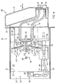
- the box-shaped support element 20 with the three functional planes arranged parallel to one another is shown in section and in plan view, and the two side walls 23, 23 ', the end plate 22 provided with the opening 22' and the one in the chamber can be seen 24 arranged partition walls 25, 25 'and 25' 'which are fastened by means not shown.
- the drive unit 15 provided with the drive motor 15 ′ and the gear 15 ′′, the ventilation valve 29, the pressure measuring device 26 and the solenoid valve 17 are fastened to the first intermediate wall 25 by means not shown.
- the solenoid valve 17 is provided with the schematically illustrated squeeze element 17 ', by means of which the elastic hose line 11 can be disconnected and opened again depending on the actuation of the solenoid valve 17 in the inserted state of the insertion element 30 (FIG. 4).
- the hose line 11 is pressed by means of the pinch element 17 ′ against a mandrel of the pinch element 17 ′, which is not shown in more detail and is designed as an abutment.
- the recesses 37', 38 ' are provided in the two webs 37 and 38 of the first hose carrier 35, as shown in FIG.
- the pressure measuring device 26 is fastened with the holder 26 'to the first intermediate wall 25 and the second intermediate wall 25'.
- the insertion and locking mechanism 60 shown in FIGS. 3 and 4 and already described above is arranged on the second intermediate wall 25 'on the side facing the first intermediate wall 25.
- the pump unit On the side facing the second intermediate wall 25 ', as shown in FIG. 9, on the third intermediate wall 25' 'the pump unit, designated as a whole by 70, is arranged and the pump wheel 80 can be seen, which is via a drive shaft 83 and via the clutch 19 is operatively connected to the drive shaft 16 of the drive unit 15.
- a toothed ring 78 provided with internal teeth 79 is fastened to the third intermediate wall 25 ′′ by means not shown.
- the internal toothing 79 of the ring gear 78 is engaged by a plurality of pinions 77 which are distributed around the inner circumference and provided with an external toothing 77 ', each individual pinion 77 being operatively connected to the pump wheel 80 via an axis 76.
- the pump wheel 80 has two disks 81 and 81 'which are arranged at a parallel distance from one another by a cylindrical intermediate piece 82.
- the rollers 75 and 75 ' are arranged between the two disks 81 and 81' and are operatively connected to the axle 76.
- the individual parts 75 to 80 of the pump unit 70 are operatively connected to one another in such a way that when the pump wheel 80 is rotated about the axis Z in the direction of the arrow R, the rollers on the pump wheel 80 are connected to the pinion 77 and ring gear 78 via the respective axis 76 Turn 75.75 'around the axis Z' in the opposite direction of rotation in the direction of the arrow R '.
Landscapes
- Health & Medical Sciences (AREA)
- Heart & Thoracic Surgery (AREA)
- Engineering & Computer Science (AREA)
- General Health & Medical Sciences (AREA)
- Veterinary Medicine (AREA)
- Anesthesiology (AREA)
- Biomedical Technology (AREA)
- Hematology (AREA)
- Life Sciences & Earth Sciences (AREA)
- Animal Behavior & Ethology (AREA)
- Public Health (AREA)
- Vascular Medicine (AREA)
- Mechanical Engineering (AREA)
- Pulmonology (AREA)
- Infusion, Injection, And Reservoir Apparatuses (AREA)
- Medical Preparation Storing Or Oral Administration Devices (AREA)
- External Artificial Organs (AREA)
- Eye Examination Apparatus (AREA)
- Reciprocating Pumps (AREA)
- Pharmaceuticals Containing Other Organic And Inorganic Compounds (AREA)
- Medicines Containing Material From Animals Or Micro-Organisms (AREA)
- Prostheses (AREA)
Priority Applications (1)
| Application Number | Priority Date | Filing Date | Title |
|---|---|---|---|
| EP98115138A EP0888788A1 (fr) | 1992-11-06 | 1993-10-20 | Tiroir pour dispositif ophtalmologique |
Applications Claiming Priority (4)
| Application Number | Priority Date | Filing Date | Title |
|---|---|---|---|
| CH3448/92 | 1992-11-06 | ||
| CH3448/92A CH685534A5 (de) | 1992-11-06 | 1992-11-06 | Einrichtung für mikrochirurgische Augenoperationen. |
| CH03096/93A CH686864A5 (de) | 1993-10-14 | 1993-10-14 | Einrichtung fuer mikrochirurgische Eingriffe am Auge eines Lebewesens. |
| CH3096/93 | 1993-10-14 |
Related Child Applications (1)
| Application Number | Title | Priority Date | Filing Date |
|---|---|---|---|
| EP98115138A Division EP0888788A1 (fr) | 1992-11-06 | 1993-10-20 | Tiroir pour dispositif ophtalmologique |
Publications (3)
| Publication Number | Publication Date |
|---|---|
| EP0601313A2 true EP0601313A2 (fr) | 1994-06-15 |
| EP0601313A3 EP0601313A3 (en) | 1994-08-17 |
| EP0601313B1 EP0601313B1 (fr) | 1999-03-03 |
Family
ID=25692167
Family Applications (2)
| Application Number | Title | Priority Date | Filing Date |
|---|---|---|---|
| EP93116916A Expired - Lifetime EP0601313B1 (fr) | 1992-11-06 | 1993-10-20 | Dispositif pour la microchirurgie de l'oeil d'un être vivant |
| EP98115138A Withdrawn EP0888788A1 (fr) | 1992-11-06 | 1993-10-20 | Tiroir pour dispositif ophtalmologique |
Family Applications After (1)
| Application Number | Title | Priority Date | Filing Date |
|---|---|---|---|
| EP98115138A Withdrawn EP0888788A1 (fr) | 1992-11-06 | 1993-10-20 | Tiroir pour dispositif ophtalmologique |
Country Status (5)
| Country | Link |
|---|---|
| US (1) | US5454783A (fr) |
| EP (2) | EP0601313B1 (fr) |
| JP (1) | JPH06261921A (fr) |
| AT (1) | ATE177012T1 (fr) |
| DE (1) | DE59309410D1 (fr) |
Cited By (4)
| Publication number | Priority date | Publication date | Assignee | Title |
|---|---|---|---|---|
| EP0717970A1 (fr) | 1994-12-20 | 1996-06-26 | GRIESHABER & CO. AG SCHAFFHAUSEN | Dispositif opthalmologique d'aspiration et irrigation et procédé de son opération |
| EP0909185A4 (fr) * | 1995-02-28 | 1999-04-21 | ||
| EP1219311A3 (fr) * | 1994-08-22 | 2002-07-17 | Kinetic Concepts, Inc. | Bidon |
| WO2010068611A1 (fr) * | 2008-12-11 | 2010-06-17 | Bausch & Lomb Incorporated | Dispositif de commande de débit de fluides aspirés |
Families Citing this family (43)
| Publication number | Priority date | Publication date | Assignee | Title |
|---|---|---|---|---|
| US6051011A (en) * | 1997-08-28 | 2000-04-18 | Bausch & Lomb Surgical, Inc. | Surgical handpiece |
| US6620189B1 (en) * | 2000-02-28 | 2003-09-16 | Radiant Medical, Inc. | Method and system for control of a patient's body temperature by way of a transluminally insertable heat exchange catheter |
| US6149274A (en) * | 1998-11-07 | 2000-11-21 | Grieshaber & Co. Ag Schaffhausen | Method of and apparatus for focusing a light flux |
| US6386835B1 (en) * | 2000-07-12 | 2002-05-14 | Fogco Systems, Inc. | Misting pump and housing system |
| US8565839B2 (en) | 2005-10-13 | 2013-10-22 | Abbott Medical Optics Inc. | Power management for wireless devices |
| US8380126B1 (en) | 2005-10-13 | 2013-02-19 | Abbott Medical Optics Inc. | Reliable communications for wireless devices |
| US9180232B2 (en) * | 2006-05-19 | 2015-11-10 | Novartis Ag | Surgical system having manifolds with integral pneumatic accumulators |
| US9522221B2 (en) * | 2006-11-09 | 2016-12-20 | Abbott Medical Optics Inc. | Fluidics cassette for ocular surgical system |
| US8414534B2 (en) | 2006-11-09 | 2013-04-09 | Abbott Medical Optics Inc. | Holding tank devices, systems, and methods for surgical fluidics cassette |
| US10959881B2 (en) | 2006-11-09 | 2021-03-30 | Johnson & Johnson Surgical Vision, Inc. | Fluidics cassette for ocular surgical system |
| US8491528B2 (en) * | 2006-11-09 | 2013-07-23 | Abbott Medical Optics Inc. | Critical alignment of fluidics cassettes |
| US7967777B2 (en) * | 2006-11-09 | 2011-06-28 | Abbott Medical Optics Inc. | Eye treatment system with multiple pumps |
| US9295765B2 (en) | 2006-11-09 | 2016-03-29 | Abbott Medical Optics Inc. | Surgical fluidics cassette supporting multiple pumps |
| US9033940B2 (en) * | 2006-11-09 | 2015-05-19 | Abbott Medical Optics Inc. | Eye treatment system with fluidics pump interface |
| JP4986687B2 (ja) * | 2007-04-05 | 2012-07-25 | アサヒビール株式会社 | 流体ストッパー装置 |
| US20110088151A1 (en) * | 2007-04-17 | 2011-04-21 | Semra Peksoz | Firefighter's turnout coat with seamless collar |
| US10596032B2 (en) | 2007-05-24 | 2020-03-24 | Johnson & Johnson Surgical Vision, Inc. | System and method for controlling a transverse phacoemulsification system with a footpedal |
| US10363166B2 (en) | 2007-05-24 | 2019-07-30 | Johnson & Johnson Surgical Vision, Inc. | System and method for controlling a transverse phacoemulsification system using sensed data |
| US10485699B2 (en) | 2007-05-24 | 2019-11-26 | Johnson & Johnson Surgical Vision, Inc. | Systems and methods for transverse phacoemulsification |
| US8162633B2 (en) * | 2007-08-02 | 2012-04-24 | Abbott Medical Optics Inc. | Volumetric fluidics pump with translating shaft path |
| US10342701B2 (en) | 2007-08-13 | 2019-07-09 | Johnson & Johnson Surgical Vision, Inc. | Systems and methods for phacoemulsification with vacuum based pumps |
| CA2733825C (fr) | 2008-11-07 | 2017-09-12 | Abbott Medical Optics Inc. | Procede de programmation des reglages d'une pedale et de controle des performances obtenues par actionnement de la pedale |
| AU2009313421B2 (en) | 2008-11-07 | 2015-03-05 | Johnson & Johnson Surgical Vision, Inc. | Semi-automatic device calibraton |
| WO2010054142A1 (fr) | 2008-11-07 | 2010-05-14 | Abbott Medical Optics Inc. | Contrôle de plusieurs pompes |
| EP2373266B1 (fr) | 2008-11-07 | 2020-04-29 | Johnson & Johnson Surgical Vision, Inc. | Dispositif à cassette chirurgicale |
| WO2010054225A2 (fr) | 2008-11-07 | 2010-05-14 | Abbott Medical Optics Inc. | Changement automatique entre différents niveaux d’aspiration appliqués à une sonde oculaire et/ou différentes pompes utilisées avec cette dernière |
| US9795507B2 (en) | 2008-11-07 | 2017-10-24 | Abbott Medical Optics Inc. | Multifunction foot pedal |
| CA2936454C (fr) | 2008-11-07 | 2018-10-23 | Abbott Medical Optics Inc. | Commande de pedale de pied ajustable pour chirurgie ophtalmique |
| CA2941759A1 (fr) | 2008-11-07 | 2010-05-14 | Abbott Medical Optics Inc. | Impulsion automatique de differents niveaux d'aspiration a une sonde oculaire |
| US9492317B2 (en) | 2009-03-31 | 2016-11-15 | Abbott Medical Optics Inc. | Cassette capture mechanism |
| US8876757B2 (en) * | 2009-11-12 | 2014-11-04 | Abbott Medical Optics Inc. | Fluid level detection system |
| CN103476371B (zh) | 2011-02-23 | 2015-12-16 | 格里沙贝眼科研究基金会 | 用于治疗青光眼的植入体 |
| US8747299B2 (en) | 2011-06-02 | 2014-06-10 | Grieshaber Ophtalmic Research Foundation | Method and device for the pathology analysis of the Schlemm's canal |
| DE202011104787U1 (de) * | 2011-08-19 | 2012-11-27 | FRITZ RUCK Ophthalmologische Systeme GmbH | Ophthalmologische Kassette |
| DE102011114468B4 (de) * | 2011-09-28 | 2016-08-11 | Carl Zeiss Meditec Ag | Ophthalmochirurgische Kassette |
| CA2875074A1 (fr) | 2012-03-17 | 2013-09-26 | Abbott Medical Optics Inc. | Cassette chirurgicale |
| CN104800906A (zh) * | 2015-03-26 | 2015-07-29 | 崔美英 | 妇科炎症治疗装置 |
| MA43427A (fr) | 2015-12-10 | 2021-05-12 | Ecolab Usa Inc | Composition de masquage d'abrasion destinée à être utilisée avec des récipients réutilisables et son procédé d'utilisation |
| EP3318290B1 (fr) | 2016-11-03 | 2020-04-22 | This AG | Cassette pour appareil ophtalmologique |
| CN109331244B (zh) * | 2018-09-28 | 2021-02-23 | 广州保瑞医疗技术有限公司 | 医用智能引流装置 |
| EP4009896A1 (fr) * | 2019-08-07 | 2022-06-15 | Biocompatibles UK Limited | Système de refroidissement pour dispositif chirurgical |
| AU2020410412A1 (en) | 2019-12-17 | 2022-08-11 | Johnson & Johnson Surgical Vision, Inc. | Systems and methods for providing a pulseless peristaltic pump |
| DE102024200411A1 (de) * | 2024-01-17 | 2025-07-17 | Geuder Aktiengesellschaft | Ophthalmologische Kassette |
Family Cites Families (10)
| Publication number | Priority date | Publication date | Assignee | Title |
|---|---|---|---|---|
| US3977624A (en) * | 1975-05-30 | 1976-08-31 | Bell Telephone Laboratories, Incorporated | Locking and drive mechanism for magnetic tape cartridge |
| US4493695A (en) * | 1982-06-01 | 1985-01-15 | Site Microsurgical Systems, Inc. | Opthalmic microsurgical system cassette assembly |
| USRE33250E (en) * | 1982-06-01 | 1990-07-03 | Site Microsurgical Systems, Inc. | Microsurgical system cassette assembly |
| US4697902A (en) * | 1985-02-20 | 1987-10-06 | Kabushiki Kaisha Toshiba | Device for containing a radiation recording medium |
| US4713051A (en) * | 1985-05-21 | 1987-12-15 | Coopervision, Inc. | Cassette for surgical irrigation and aspiration and sterile package therefor |
| US4798580A (en) * | 1987-04-27 | 1989-01-17 | Site Microsurgical Systems, Inc. | Disposable peristaltic pump cassette system |
| US5125891A (en) * | 1987-04-27 | 1992-06-30 | Site Microsurgical Systems, Inc. | Disposable vacuum/peristaltic pump cassette system |
| US4904168A (en) * | 1988-12-28 | 1990-02-27 | United Sonics, Inc. | Cassette assembly for ophthalmic surgery system |
| US4963131A (en) * | 1989-03-16 | 1990-10-16 | Surgin Surgical Instrumentation, Inc. | Disposable cassette for ophthalmic surgery applications |
| US5106366A (en) * | 1990-03-08 | 1992-04-21 | Nestle, S.A. | Medical fluid cassette and control system |
-
1993
- 1993-10-20 EP EP93116916A patent/EP0601313B1/fr not_active Expired - Lifetime
- 1993-10-20 AT AT93116916T patent/ATE177012T1/de not_active IP Right Cessation
- 1993-10-20 DE DE59309410T patent/DE59309410D1/de not_active Expired - Fee Related
- 1993-10-20 EP EP98115138A patent/EP0888788A1/fr not_active Withdrawn
- 1993-11-02 JP JP5274583A patent/JPH06261921A/ja active Pending
- 1993-11-04 US US08/148,152 patent/US5454783A/en not_active Expired - Fee Related
Cited By (10)
| Publication number | Priority date | Publication date | Assignee | Title |
|---|---|---|---|---|
| EP1219311A3 (fr) * | 1994-08-22 | 2002-07-17 | Kinetic Concepts, Inc. | Bidon |
| US7611500B1 (en) | 1994-08-22 | 2009-11-03 | Kci Licensing, Inc. | Wound therapy device and related methods |
| US8202262B2 (en) | 1994-08-22 | 2012-06-19 | Kci Licensing, Inc. | Wound therapy device and related methods |
| EP0717970A1 (fr) | 1994-12-20 | 1996-06-26 | GRIESHABER & CO. AG SCHAFFHAUSEN | Dispositif opthalmologique d'aspiration et irrigation et procédé de son opération |
| EP0909185A4 (fr) * | 1995-02-28 | 1999-04-21 | ||
| WO2010068611A1 (fr) * | 2008-12-11 | 2010-06-17 | Bausch & Lomb Incorporated | Dispositif de commande de débit de fluides aspirés |
| US7819837B2 (en) | 2008-12-11 | 2010-10-26 | Bausch & Lomb Incorporated | Device for controlling flow rate of aspirated fluids |
| CN102245140A (zh) * | 2008-12-11 | 2011-11-16 | 博士伦公司 | 用于控制抽吸流体的流率的装置 |
| JP2012511957A (ja) * | 2008-12-11 | 2012-05-31 | ボシュ・アンド・ロム・インコーポレイテッド | 吸引した流体の流量を制御するための装置 |
| CN102245140B (zh) * | 2008-12-11 | 2013-10-30 | 博士伦公司 | 用于控制抽吸流体的流率的装置 |
Also Published As
| Publication number | Publication date |
|---|---|
| ATE177012T1 (de) | 1999-03-15 |
| DE59309410D1 (de) | 1999-04-08 |
| US5454783A (en) | 1995-10-03 |
| EP0601313A3 (en) | 1994-08-17 |
| EP0888788A1 (fr) | 1999-01-07 |
| JPH06261921A (ja) | 1994-09-20 |
| EP0601313B1 (fr) | 1999-03-03 |
Similar Documents
| Publication | Publication Date | Title |
|---|---|---|
| EP0601313A2 (fr) | Dispositif pour la microchirurgie de l'oeil d'un être vivant | |
| DE69432253T2 (de) | Apparat zum herstellen einer gebogenen bohrung | |
| DE69332440T2 (de) | WECHSELLADESYSTEM FüR KASSETTEN FÜR EIN CHIRURGISCHES INSTRUMENT | |
| DE69509641T2 (de) | Nähgerät | |
| EP0800798B1 (fr) | Dispositif d'application pour substances dentaires | |
| DE4136737C2 (de) | Endoskop | |
| DE4310555C1 (de) | Chirurgische Nähmaschine | |
| DE69101441T2 (de) | Rohr zum einführen in einem körper mit biegemechanismus. | |
| DE2435912C2 (de) | Folge-Quetschventil | |
| DE3876143T2 (de) | Wegwerfbare infusionskassette mit pumpenkammer sowie triebwerk dafuer. | |
| DE102004009384B4 (de) | Videoendoskopisches System | |
| DE2026861C3 (de) | Vorrichtung zum Anbringen von Zetteln an einem Tragkörper bspw. an einem Stoff | |
| DE3931719A1 (de) | Endoskop | |
| DE69024880T2 (de) | Biegeeinrichtung | |
| DE19952244A1 (de) | Bedienteil eines Behandlungsinstrumentes für ein Endoskop | |
| DE2858034C2 (fr) | ||
| DE4312817A1 (de) | Ohrdurchstechvorrichtung für einen nicht entfernbaren Ohrring mit Kupplung | |
| DE102020211128A1 (de) | Endoskop mit einer funktion zur verhinderung einer kettenverklemmung | |
| EP3829677A1 (fr) | Système de perfusion comprenant une pompe de perfusion et un module de pompage pouvant être accouplé à celle-ci | |
| DE202008002887U1 (de) | Vorrichtung zum Trennen mindestens eines Lichtwellenleiters | |
| CH686864A5 (de) | Einrichtung fuer mikrochirurgische Eingriffe am Auge eines Lebewesens. | |
| EP2679255B1 (fr) | Système de pompe, pompe tubulaire et cassette tubulaire ainsi que procédé de configuration d'un système de pompe | |
| DE69412920T2 (de) | Verbesserungen an zyclischem Bildbetrachtungsgeräten | |
| CH632144A5 (de) | Medizinisches geraet mit einem kasten fuer medizinische, insbesondere zahnaerztliche instrumente. | |
| CH685534A5 (de) | Einrichtung für mikrochirurgische Augenoperationen. |
Legal Events
| Date | Code | Title | Description |
|---|---|---|---|
| PUAI | Public reference made under article 153(3) epc to a published international application that has entered the european phase |
Free format text: ORIGINAL CODE: 0009012 |
|
| AK | Designated contracting states |
Kind code of ref document: A2 Designated state(s): AT CH DE ES FR GB IT LI NL SE |
|
| PUAL | Search report despatched |
Free format text: ORIGINAL CODE: 0009013 |
|
| AK | Designated contracting states |
Kind code of ref document: A3 Designated state(s): AT CH DE ES FR GB IT LI NL SE |
|
| 17P | Request for examination filed |
Effective date: 19941118 |
|
| 17Q | First examination report despatched |
Effective date: 19960807 |
|
| GRAG | Despatch of communication of intention to grant |
Free format text: ORIGINAL CODE: EPIDOS AGRA |
|
| GRAG | Despatch of communication of intention to grant |
Free format text: ORIGINAL CODE: EPIDOS AGRA |
|
| GRAH | Despatch of communication of intention to grant a patent |
Free format text: ORIGINAL CODE: EPIDOS IGRA |
|
| GRAH | Despatch of communication of intention to grant a patent |
Free format text: ORIGINAL CODE: EPIDOS IGRA |
|
| GRAA | (expected) grant |
Free format text: ORIGINAL CODE: 0009210 |
|
| AK | Designated contracting states |
Kind code of ref document: B1 Designated state(s): AT CH DE ES FR GB IT LI NL SE |
|
| PG25 | Lapsed in a contracting state [announced via postgrant information from national office to epo] |
Ref country code: SE Free format text: THE PATENT HAS BEEN ANNULLED BY A DECISION OF A NATIONAL AUTHORITY Effective date: 19990303 Ref country code: ES Free format text: THE PATENT HAS BEEN ANNULLED BY A DECISION OF A NATIONAL AUTHORITY Effective date: 19990303 |
|
| REF | Corresponds to: |
Ref document number: 177012 Country of ref document: AT Date of ref document: 19990315 Kind code of ref document: T |
|
| REG | Reference to a national code |
Ref country code: CH Ref legal event code: NV Representative=s name: ALTHOFF PATENTANWALTSBUERO Ref country code: CH Ref legal event code: EP |
|
| GBT | Gb: translation of ep patent filed (gb section 77(6)(a)/1977) |
Effective date: 19990303 |
|
| REF | Corresponds to: |
Ref document number: 59309410 Country of ref document: DE Date of ref document: 19990408 |
|
| ET | Fr: translation filed | ||
| PGFP | Annual fee paid to national office [announced via postgrant information from national office to epo] |
Ref country code: GB Payment date: 19991012 Year of fee payment: 7 |
|
| PG25 | Lapsed in a contracting state [announced via postgrant information from national office to epo] |
Ref country code: AT Free format text: LAPSE BECAUSE OF NON-PAYMENT OF DUE FEES Effective date: 19991020 |
|
| PGFP | Annual fee paid to national office [announced via postgrant information from national office to epo] |
Ref country code: FR Payment date: 19991021 Year of fee payment: 7 |
|
| PGFP | Annual fee paid to national office [announced via postgrant information from national office to epo] |
Ref country code: NL Payment date: 19991026 Year of fee payment: 7 |
|
| PGFP | Annual fee paid to national office [announced via postgrant information from national office to epo] |
Ref country code: CH Payment date: 19991209 Year of fee payment: 7 |
|
| PGFP | Annual fee paid to national office [announced via postgrant information from national office to epo] |
Ref country code: DE Payment date: 19991222 Year of fee payment: 7 |
|
| PLBE | No opposition filed within time limit |
Free format text: ORIGINAL CODE: 0009261 |
|
| STAA | Information on the status of an ep patent application or granted ep patent |
Free format text: STATUS: NO OPPOSITION FILED WITHIN TIME LIMIT |
|
| 26N | No opposition filed | ||
| PG25 | Lapsed in a contracting state [announced via postgrant information from national office to epo] |
Ref country code: GB Free format text: LAPSE BECAUSE OF NON-PAYMENT OF DUE FEES Effective date: 20001020 |
|
| PG25 | Lapsed in a contracting state [announced via postgrant information from national office to epo] |
Ref country code: LI Free format text: LAPSE BECAUSE OF NON-PAYMENT OF DUE FEES Effective date: 20001031 Ref country code: CH Free format text: LAPSE BECAUSE OF NON-PAYMENT OF DUE FEES Effective date: 20001031 |
|
| PG25 | Lapsed in a contracting state [announced via postgrant information from national office to epo] |
Ref country code: NL Free format text: LAPSE BECAUSE OF NON-PAYMENT OF DUE FEES Effective date: 20010501 |
|
| GBPC | Gb: european patent ceased through non-payment of renewal fee |
Effective date: 20001020 |
|
| REG | Reference to a national code |
Ref country code: CH Ref legal event code: PL |
|
| PG25 | Lapsed in a contracting state [announced via postgrant information from national office to epo] |
Ref country code: FR Free format text: LAPSE BECAUSE OF NON-PAYMENT OF DUE FEES Effective date: 20010629 |
|
| NLV4 | Nl: lapsed or anulled due to non-payment of the annual fee |
Effective date: 20010501 |
|
| PG25 | Lapsed in a contracting state [announced via postgrant information from national office to epo] |
Ref country code: DE Free format text: LAPSE BECAUSE OF NON-PAYMENT OF DUE FEES Effective date: 20010703 |
|
| REG | Reference to a national code |
Ref country code: FR Ref legal event code: ST |
|
| PG25 | Lapsed in a contracting state [announced via postgrant information from national office to epo] |
Ref country code: IT Free format text: LAPSE BECAUSE OF NON-PAYMENT OF DUE FEES;WARNING: LAPSES OF ITALIAN PATENTS WITH EFFECTIVE DATE BEFORE 2007 MAY HAVE OCCURRED AT ANY TIME BEFORE 2007. THE CORRECT EFFECTIVE DATE MAY BE DIFFERENT FROM THE ONE RECORDED. Effective date: 20051020 |