EP0601326A1 - Türschliesser-Ankopplung - Google Patents
Türschliesser-Ankopplung Download PDFInfo
- Publication number
- EP0601326A1 EP0601326A1 EP93117543A EP93117543A EP0601326A1 EP 0601326 A1 EP0601326 A1 EP 0601326A1 EP 93117543 A EP93117543 A EP 93117543A EP 93117543 A EP93117543 A EP 93117543A EP 0601326 A1 EP0601326 A1 EP 0601326A1
- Authority
- EP
- European Patent Office
- Prior art keywords
- door
- door closer
- floor
- coupling
- frame
- Prior art date
- Legal status (The legal status is an assumption and is not a legal conclusion. Google has not performed a legal analysis and makes no representation as to the accuracy of the status listed.)
- Granted
Links
- 230000008878 coupling Effects 0.000 title claims abstract description 26
- 238000010168 coupling process Methods 0.000 title claims abstract description 26
- 238000005859 coupling reaction Methods 0.000 title claims abstract description 26
- 239000011521 glass Substances 0.000 claims abstract description 16
- 238000010276 construction Methods 0.000 claims description 3
- 238000005192 partition Methods 0.000 claims description 2
- 238000009434 installation Methods 0.000 abstract description 2
- 239000000725 suspension Substances 0.000 description 2
- 239000004568 cement Substances 0.000 description 1
- 238000009408 flooring Methods 0.000 description 1
- 230000003287 optical effect Effects 0.000 description 1
- 230000000007 visual effect Effects 0.000 description 1
Images

Classifications
-
- E—FIXED CONSTRUCTIONS
- E05—LOCKS; KEYS; WINDOW OR DOOR FITTINGS; SAFES
- E05D—HINGES OR SUSPENSION DEVICES FOR DOORS, WINDOWS OR WINGS
- E05D15/00—Suspension arrangements for wings
- E05D15/06—Suspension arrangements for wings for wings sliding horizontally more or less in their own plane
- E05D15/0604—Suspension arrangements for wings for wings sliding horizontally more or less in their own plane allowing an additional movement
- E05D15/0608—Suspension arrangements for wings for wings sliding horizontally more or less in their own plane allowing an additional movement caused by track lay-out
- E05D15/0613—Suspension arrangements for wings for wings sliding horizontally more or less in their own plane allowing an additional movement caused by track lay-out with multi-directional trolleys
-
- E—FIXED CONSTRUCTIONS
- E05—LOCKS; KEYS; WINDOW OR DOOR FITTINGS; SAFES
- E05F—DEVICES FOR MOVING WINGS INTO OPEN OR CLOSED POSITION; CHECKS FOR WINGS; WING FITTINGS NOT OTHERWISE PROVIDED FOR, CONCERNED WITH THE FUNCTIONING OF THE WING
- E05F3/00—Closers or openers with braking devices, e.g. checks; Construction of pneumatic or liquid braking devices
- E05F3/22—Additional arrangements for closers, e.g. for holding the wing in opened or other position
-
- E—FIXED CONSTRUCTIONS
- E06—DOORS, WINDOWS, SHUTTERS, OR ROLLER BLINDS IN GENERAL; LADDERS
- E06B—FIXED OR MOVABLE CLOSURES FOR OPENINGS IN BUILDINGS, VEHICLES, FENCES OR LIKE ENCLOSURES IN GENERAL, e.g. DOORS, WINDOWS, BLINDS, GATES
- E06B3/00—Window sashes, door leaves, or like elements for closing wall or like openings; Layout of fixed or moving closures, e.g. windows in wall or like openings; Features of rigidly-mounted outer frames relating to the mounting of wing frames
- E06B3/02—Wings made completely of glass
-
- E—FIXED CONSTRUCTIONS
- E05—LOCKS; KEYS; WINDOW OR DOOR FITTINGS; SAFES
- E05D—HINGES OR SUSPENSION DEVICES FOR DOORS, WINDOWS OR WINGS
- E05D5/00—Construction of single parts, e.g. the parts for attachment
- E05D5/02—Parts for attachment, e.g. flaps
- E05D5/0246—Parts for attachment, e.g. flaps for attachment to glass panels
-
- E—FIXED CONSTRUCTIONS
- E05—LOCKS; KEYS; WINDOW OR DOOR FITTINGS; SAFES
- E05Y—INDEXING SCHEME ASSOCIATED WITH SUBCLASSES E05D AND E05F, RELATING TO CONSTRUCTION ELEMENTS, ELECTRIC CONTROL, POWER SUPPLY, POWER SIGNAL OR TRANSMISSION, USER INTERFACES, MOUNTING OR COUPLING, DETAILS, ACCESSORIES, AUXILIARY OPERATIONS NOT OTHERWISE PROVIDED FOR, APPLICATION THEREOF
- E05Y2800/00—Details, accessories and auxiliary operations not otherwise provided for
- E05Y2800/67—Materials; Strength alteration thereof
- E05Y2800/672—Glass
-
- E—FIXED CONSTRUCTIONS
- E05—LOCKS; KEYS; WINDOW OR DOOR FITTINGS; SAFES
- E05Y—INDEXING SCHEME ASSOCIATED WITH SUBCLASSES E05D AND E05F, RELATING TO CONSTRUCTION ELEMENTS, ELECTRIC CONTROL, POWER SUPPLY, POWER SIGNAL OR TRANSMISSION, USER INTERFACES, MOUNTING OR COUPLING, DETAILS, ACCESSORIES, AUXILIARY OPERATIONS NOT OTHERWISE PROVIDED FOR, APPLICATION THEREOF
- E05Y2900/00—Application of doors, windows, wings or fittings thereof
- E05Y2900/10—Application of doors, windows, wings or fittings thereof for buildings or parts thereof
- E05Y2900/13—Type of wing
- E05Y2900/132—Doors
-
- E—FIXED CONSTRUCTIONS
- E05—LOCKS; KEYS; WINDOW OR DOOR FITTINGS; SAFES
- E05Y—INDEXING SCHEME ASSOCIATED WITH SUBCLASSES E05D AND E05F, RELATING TO CONSTRUCTION ELEMENTS, ELECTRIC CONTROL, POWER SUPPLY, POWER SIGNAL OR TRANSMISSION, USER INTERFACES, MOUNTING OR COUPLING, DETAILS, ACCESSORIES, AUXILIARY OPERATIONS NOT OTHERWISE PROVIDED FOR, APPLICATION THEREOF
- E05Y2900/00—Application of doors, windows, wings or fittings thereof
- E05Y2900/10—Application of doors, windows, wings or fittings thereof for buildings or parts thereof
- E05Y2900/13—Type of wing
- E05Y2900/142—Partition walls
Definitions
- the invention relates to a door closer, which in a frame of a partition or glass entrance front, which consists in particular of several attachable wall elements, in which each wall element is individually equipped with at least one support device and is suspended movable in a ceiling rail.
- These types of wall elements are preferably used in the front areas of buildings, in particular in shops and restaurants, in order to keep the shop freely accessible or closed depending on the weather. For this reason it is necessary that the entire front can be parked in a side position so that there is no hindrance to the incoming public traffic.
- a door preferably an all-glass door, is usually located within these displaceable wall elements, although this can also be framed. So that this door is not open in cold seasons when the front is closed, these doors are also equipped with door closers.
- US 3,091,819 shows a door closer coupling in which the coupling between the door closer installed in the frame above the door is carried out via a pin, but at the same time the door leaf is also guided in the area near the floor.
- the object of the invention is to provide an assembly-friendly coupling between a door closer installed above the door and a prefabricated all-glass or framed leaf with all fittings, the all-glass leaf not being guided in the area near the floor.
- a door closer should also be possible if it is an existing system, but special attention should be paid to the fact that the door closer, as is the case with the floor door closer, for example, does not appear to the user.
- a frame door closer which is invisible to the user is used within the cross member located above the door.
- This frame door closer has a drive axle which emerges towards the floor and which is provided with a continuous bore running transversely to the wall front.
- This coupling pin is secured by a screw connection and there is normal swinging operation of the door.
- the particular advantage of this coupling is that the entire door element with all fittings can be preassembled and only needs to be connected to the drive axle of the frame door closer at the construction site. The door element is free in the area near the floor.
- the door is to be designed as a swing door, all that is left is to provide a hole for an axle bearing in the floor, which can consist, for example, of a push-out bolt.
- the entire weight of the door element depends on the drive axis of the frame door closer. If the door element is to be moved, the second suspension point is reached via a lock in the upper area of the door leaf with the frame above it.
- the door is first placed on an inclined base, and by tipping from this inclined position, the coupling pin is inserted into the hole in the frame door closer and secured. The pad can then be removed.
- the door element is non-positively and positively connected to the frame door closer.
- a further advantage over floor door closers that have been customary up to now is that no expensive chiselling work in the floor area is necessary for the large cement box of the floor door closer. This is a very important argument, especially in existing systems, because this floor work can cause enormous damage to the flooring. Any inaccuracies in the height of the door can be compensated for by a height adjustment screw, which is located above the frame door closer. As it turns out, such a door system can also be used as a normally accessible door in connection with a lower axle bolt.
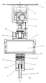
- FIG 2 an overall assembly of the fittings, the door and the frame door closer is shown once as an exploded view.
- the all-glass door (8) is provided with rubber coverings (11) which are inserted in the areas where the swing door fittings (9) and (10) cover and fit the glass recess (23).
- the swing door fittings (9) and (10) are firmly connected to each other by the screw connection (15).
- the receptacle (24) with the coupling pin (13) located therein is inserted into the swing door fitting (9).
- This receptacle (24) is attached to the swing door fitting by means of the screw connection (16) (9) connected. In this position, the coupling pin (13) engages in the receiving bore (14) of the drive axle (7) of the frame door closer (6).
- a counter plate (17) is placed on the opposite side, which is secured with the screw connection (16) or another suitable securing device. This ensures that there is a secure non-positive and positive connection between the frame door closer (6) and the all-glass door (8). For visual reasons, the entire swing door fitting is covered by cover profiles (12) on both sides.
- the system is quickly ready for use and can move freely in its pendulum movement via an axle pin (not shown) in the floor, which can be pushed out, or can be moved as a part or as a whole to a safe parking position without the coupling between the door leaf and the To release door closers, because the frame door closer is also moved, and the second suspension point of the all-glass door (8) can be reached via a lock, not shown, on the top of the door leaf.
- the entire floor area is free from annoying connecting axes and floor guides.
Landscapes
- Engineering & Computer Science (AREA)
- Civil Engineering (AREA)
- Structural Engineering (AREA)
- Mechanical Engineering (AREA)
- Power-Operated Mechanisms For Wings (AREA)
- Support Devices For Sliding Doors (AREA)
- Securing Of Glass Panes Or The Like (AREA)
- Specific Sealing Or Ventilating Devices For Doors And Windows (AREA)
- Wing Frames And Configurations (AREA)
- Lock And Its Accessories (AREA)
- Seal Device For Vehicle (AREA)
- Lighting Device Outwards From Vehicle And Optical Signal (AREA)
- Liquid Crystal (AREA)
- Joining Of Corner Units Of Frames Or Wings (AREA)
- Window Of Vehicle (AREA)
- Stereophonic System (AREA)
- Medicines Containing Antibodies Or Antigens For Use As Internal Diagnostic Agents (AREA)
- Stereo-Broadcasting Methods (AREA)
Abstract
Description
- Die Erfindung betrifft einen Türschließer, der in einem Rahmen einer Trennwand oder Glaseingangsfront, die insbesondere aus mehreren aneinandersetzbaren Wandelementen besteht, bei der jedes Wandelement einzeln mit wenigstens einer Tragvorrichtung ausgerüstet und in einer Deckenschiene verfahrbar aufgehängt ist. Diese Art von Wandelementen werden vorzugsweise in Frontbereichen von Gebäuden verwendet, hier insbesondere bei Geschäften und Gaststätten, um entsprechend der Witterung das Ladenlokal frei zugänglich bzw. verschlossen zu halten. Aus diesem Grunde ist es notwendig, daß die gesamte Front in einer Seitenposition geparkt werden kann, damit für den eintretenden Publikumsverkehr keine Behinderung stattfindet. Innerhalb dieser verschiebbaren Wandelemente befindet sich in der Regel eine Tür, vorzugsweise eine Ganzglastür, die allerdings auch gerahmt sein kann. Damit in kalten Jahreszeiten diese Tür nicht offensteht bei einer geschlossenen Front, sind diese Türen auch mit Türschließern ausgerüstet. Diese Türschließer werden in den Bodenbereich eingelassen und haben über ihre herausstehende Achse eine Ankopplung an das darüber befindliche Türblatt. Diese Ankopplung wird in der Regel über einen vorstehenden Achsaustritt des Türschließers erreicht. Dieses stellt jedoch ein Gefahrenmoment dar, und zwar in dem Augenblick, wenn das gesamte Wandelement in seine Parkposition gebracht worden ist. Denn in dieser Stellung ist der Bodenbereich frei, und es könnten hier Stolperstellen sich auftun. Zum anderen verschmutzen durch den Publikumsverkehr die im Bodenbereich liegenden Bohrungen für die Ankopplung.
- Ausgehend von diesem Stand der Technik ist aus der europäischen Patentanmeldung 0 340 795 A2 ein Bodentürschließer für Schwenk- und/oder Pendeltüren bekanntgeworden. Hier wird an der Unterseite der Tür ein Adapter angeschraubt, der mit seiner Steckachse die Verbindung zum in den Boden eingelassenen Türschließer herstellt.
- Der US 3,091,819 ist eine Türschließerankopplung zu entnehmen, bei der die Kopplung zwischen dem im Rahmen oberhalb der Tür eingebauten Türschließer über einen Stift durchgeführt wird, gleichzeitig wird aber der Türflügel auch im bodennahen Bereich geführt.
- Die Aufgabe der Erfindung ist es, eine montagefreundliche Ankopplung zwischen einem oberhalb der Tür eingebauten Türschließer und einem vorgefertigten Ganzglas- bzw. gerahmten Flügel mit sämtlichen Beschlägen zu schaffen, wobei die Ganzglasflügel im bodennahen Bereich nicht geführt sind. Darüber hinaus soll der Anbau eines Türschließers auch dann möglich sein, wenn es sich um bestehende Anlagen handelt, hierbei ist jedoch besonderer Augenmerk darauf zu richten, daß der Türschließer, wie es beispielsweise beim Bodentürschließer der Fall ist, für den Benutzer nicht in Erscheinung tritt.
- Die Lösung der Aufgabe wird dadurch erreicht, daß innerhalb des oberhalb der Tür liegenden Querholmes ein für den Benutzer unsichtbarer Rahmentürschließer eingesetzt wird. Dieser Rahmentürschließer hat eine zum Boden hin austretende Antriebsachse, die mit einer quer zur Wandfront verlaufenden durchgehenden Bohrung versehen ist. In diese Bohrung greift ein an dem Türblatt vormontierter Ankoppelstift, welcher mit dem Beschlag der Tür verbunden ist. Durch eine Verschraubung wird dieser Ankoppelstift gesichert und es ist ein normaler Pendelbetrieb der Tür gegeben. Der besondere Vorteil dieser Ankopplung liegt darin, daß das gesamte Türelement mit sämtlichen Beschlagteilen vormontiert werden kann und auf der Baustelle nur noch mit der Antriebsachse des Rahmentürschließers verbunden werden muß. Das Türelement ist im bodennahmen Bereich dabei frei. Soll die Tür als Pendeltür ausgebildet werden, so ist im Boden lediglich noch eine Bohrung für ein Achslager vorzusehen, daß beispielsweise aus einem herausdrückbaren Bolzen bestehen kann. Dabei hängt das gesamte Gewicht des Türelementes an der Antriebsachse des Rahmentürschließers. Soll das Türelement verschoben werden, so wird der zweite Aufhängepunkt über eine Verriegelung im oberen Bereich des Türflügels mit dem darüber befindlichen Rahmen erreicht. Bei der Montage wird die Tür zunächst auf eine schräge Unterlage gesetzt, und durch Kippen aus dieser Schräglage wird der Ankoppelstift in die Bohrung des Rahmentürschließers eingesetzt und gesichert. Danach kann die Unterlage entfernt werden. Das Türelement ist mit dem Rahmentürschließer kraft- und formschlüssig verbunden. Ein weiterer Vorteil gegenüber bisher üblichen Bodentürschließern liegt darin, daß keine aufwendigen Stemmarbeiten im Fußbodenbereich für den großen Zementkasten des Bodentürschliessers notwendig sind. Dieses ist gerade bei bestehenden Anlagen ein sehr wichtiges Argument, weil durch diese Bodenarbeiten enorme Beschädigungen des Bodenbelages auftreten können. Etwaige Ungenauigkeiten in der Höhenlage der Tür können durch eine Höhenstellschraube, welche sich oberhalb des Rahmentürschließers befindet, ausgeglichen werden. Wie sich zeigt, kann eine solche Türanlage auch als normal begehbare Tür in Verbindung mit einem unteren Achsbolzen verwendet werden.
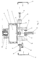
- Die Erfindung wird an einem schematisch dargestellten möglichen Ausführungsbeispiel in den Zeichnungen erläutert.
- Es zeigt:
- Figur 1:
- Aufhängung der Tür im Schnitt
- Figur 2:
- Montage der Ankopplung
- Figur 3:
- Montage der Tür
- Figur 4:
- fertigmontierte Tür in der Vorderansicht
- In der Figur 2 wird eine Gesamtmontage der Beschlagteile, der Tür und dem Rahmentürschließer als Explosionszeichnung einmal dargestellt. Die Ganzglastür (8) wird mit Gummibelägen (11) versehen, die in den Bereichen, wo die Pendeltürbeschläge (9) und (10) die Glasausnehmung (23) überdecken und angebracht sind, eingeschoben werden. Die Pendeltürbeschläge (9) und (10) werden durch die Verschraubung (15) miteinander fest verbunden. Gleichzeitig wird in den Pendeltürbeschlag (9) die Aufnahme (24) mit dem darin befindlichen Ankoppelstift (13) eingesetzt. Diese Aufnahme (24) wird mittels der Verschraubung (16) mit dem Pendeltürbeschlag (9) verbunden. Der Ankoppelstift (13) greift in dieser Position in die Aufnahmebohrung (14) der Antriebsachse (7) des Rahmentürschließers (6). Damit der Ankoppelstift (13) nicht wieder herausrutschen kann, wird auf der Gegenseite eine Gegenplatte (17) gegengesetzt, die mit der Verschraubung (16) oder einem anderen geeigneten Sicherungsmittel gesichert wird. Hierdurch wird sichergestellt, daß eine sichere kraft- und formschlüssige Verbindung zwischen dem Rahmentürschließer (6) und der Ganzglastür (8) besteht. Aus optischen Gründen wird der gesamte Pendeltürbeschlag durch Abdeckprofile (12) auf beiden Seiten abgedeckt.
- Die vorbeschriebene Art der Montage ist jedoch nicht üblich, da davon ausgegangen wird, daß die Tür in ihrer Gesamtheit mit sämtlichen Beschlägen im Werk vormontiert wird. Dieses vormontierte Türblatt wird, wie in Figur 3 dargestellt ist, auf der Baustelle eingesetzt. Der Bodenbeschlag (19) wird auf einer nur zur einfacheren Montage benötigten Unterlagen (25) auf dem Fußboden (18) schräg angesetzt. Aus der Schräglage wird die Ganzglastür (8) nun angehoben und in die Position gebracht, in der mit dem Ankoppelstift (13) über die Aufnahmebohrung (14) eine kraft- und formschlüssige Verbindung mit dem Rahmentürschließer eingegangen werden kann. Anschließend ist nur noch die Gegenplatte (17) mit der Verschraubung (16) zur Sicherung der Tür anzubringen. Eine notwendige Höhenkorrektur kann bei etwaigen Ungenauigkeiten des Fußbodens mittels der Höhenverstellung (3), die sich oberhalb des Rahmenprofiles (5) befindet, ausgeglichen werden. Durch diese einfache Montageart ist die Anlage schnell gebrauchsfertig und kann sowohl in ihrer Pendelbewegung über einen nicht dargestellten Achsstift im Boden, welcher herausdrückbar ist, sich frei bewegen oder auch als Teil oder Gesamtanlage in eine sichere Parkposition verbracht werden ohne die Ankopplung zwischen dem Türblatt und dem Türschließer zu lösen, weil der Rahmentürschließer mit verschoben wird, und der zweite Aufhängepunkt der Ganzglastür (8) über eine nicht dargestellte Verriegelung oben an dem Türflügel erreicht werden kann. Wenn die Tür sich in einer Parkposition befindet, ist somit der gesamte Bodenbereich frei von störenden Anschlußachsen und Bodenführungen.
-
- 1.
- Decke
- 2.
- Laufrollenprofil
- 3.
- Höhenverstellung
- 4.
- Laufrollen
- 5.
- Rahmenprofil
- 6.
- Rahmentürschließer
- 7.
- Antriebsachse
- 8.
- Ganzglastür
- 9.
- Pendeltürbeschlag
- 10.
- Pendeltürbeschlag
- 11.
- Gummibeilage
- 12.
- Abdeckprofil
- 13.
- Ankoppelstift
- 14.
- Aufnahmebohrung
- 15.
- Verschraubung
- 16.
- Verschraubung
- 17.
- Gegenplatte
- 18.
- Fußboden
- 19.
- Bodenbeschlag
- 20.
- Zapfen
- 21.
- Gegenlager
- 23.
- Glasausnehmung
- 24.
- Aufnahme
- 25.
- Unterlage
Claims (3)
- Türschließerankopplung eines Türschließers für einen in einem verschiebbaren Wandelement einer Trennwand oder Glaseingangsfront angeordneten Pendel-Schiebeflügel, wobei die Wandelemente beweglich über Rollen in/an einem Laufrollenprofil befestigt sind, und im bodennahen Bereich nicht geführt werden, dadurch gekennzeichnet, daß der Türschließer (6) innerhalb einer Rahmenkonstruktion des Wandelementes in dessen oberem horizontalen Profil (5) verdeckt so eingebaut wird, daß seine austretende Antriebsachse (7) zum Fußboden (18) weist und die Antriebsachse (7) eine quer zum Türblatt der Ganzglastür (8) liegende Aufnahmebohrung (14) hat, in die ein innerhalb des Pendeltürbeschlages (9) und (10) liegender Ankoppelstift (13) eingreift, der gegen Herausrutschen gesichert wird.
- Türschließer-Ankopplung nach Anspruch 1, dadurch gekennzeichnet, daß die Ganzglastür (8) mit allen Beschlagteilen vormontiert an die Antriebsachse (7) des Türschließers (6) angesetzt werden kann.
- Türschließer-Ankopplung nach Anspruch 1, dadurch gekennzeichnet, daß die Ganzglastür (8) mit dem angeschlossenen Türschließer (6) über das Laufrollenprofil (2) verschoben werden kann.
Applications Claiming Priority (3)
| Application Number | Priority Date | Filing Date | Title |
|---|---|---|---|
| DE4133578A DE4133578A1 (de) | 1991-10-10 | 1991-10-10 | Tuerschliesserankopplung |
| WOPCT/DE92/00951 | 1992-11-11 | ||
| PCT/DE1992/000951 WO1994011607A1 (de) | 1991-10-10 | 1992-11-11 | Türschliesser-ankopplung |
Publications (2)
| Publication Number | Publication Date |
|---|---|
| EP0601326A1 true EP0601326A1 (de) | 1994-06-15 |
| EP0601326B1 EP0601326B1 (de) | 1996-07-17 |
Family
ID=25908107
Family Applications (1)
| Application Number | Title | Priority Date | Filing Date |
|---|---|---|---|
| EP93117543A Expired - Lifetime EP0601326B1 (de) | 1991-10-10 | 1993-10-29 | Türschliesser-Ankopplung |
Country Status (7)
| Country | Link |
|---|---|
| EP (1) | EP0601326B1 (de) |
| AT (1) | ATE140508T1 (de) |
| DE (2) | DE4133578A1 (de) |
| DK (1) | DK0601326T3 (de) |
| ES (1) | ES2065878T3 (de) |
| FI (1) | FI101317B (de) |
| WO (1) | WO1994011607A1 (de) |
Cited By (1)
| Publication number | Priority date | Publication date | Assignee | Title |
|---|---|---|---|---|
| DE102017106258A1 (de) * | 2017-03-23 | 2018-09-27 | JOSKO Fenster und Türen GmbH | Kombination eines schwenkbaren Tür- oder Fensterflügels mit einem Tür- oder Fensterstock, Kombination einer Schiebetür oder eines Schiebefenster mit einem Tür- oder Fensterstock sowie Fixfensterteil |
Families Citing this family (3)
| Publication number | Priority date | Publication date | Assignee | Title |
|---|---|---|---|---|
| US5544462A (en) * | 1993-11-02 | 1996-08-13 | Dorma Gmbh + Co. Kg | Movable wall system |
| DE19702024B4 (de) * | 1997-01-23 | 2007-09-20 | Dorma Gmbh + Co. Kg | Ortsveränderliche Wand |
| DE19959825C1 (de) * | 1999-12-10 | 2001-07-26 | Dorma Gmbh & Co Kg | Schiebewand mit mehreren seitlich verschiebbaren Wandelementen |
Citations (3)
| Publication number | Priority date | Publication date | Assignee | Title |
|---|---|---|---|---|
| US3091819A (en) * | 1960-09-20 | 1963-06-04 | Brasco Mfg Company | Door control mechanism |
| US3149366A (en) * | 1960-10-18 | 1964-09-22 | Republic Industries | Concealed overhead door closer |
| DE2410623A1 (de) * | 1974-03-06 | 1975-09-18 | Glos Fa Georg | Tueranlage mit einer mehrzahl von verschiebbaren pendeltuerfluegeln |
Family Cites Families (1)
| Publication number | Priority date | Publication date | Assignee | Title |
|---|---|---|---|---|
| DE8806052U1 (de) * | 1988-05-06 | 1988-09-29 | Dorma-Glas Gesellschaft für Glastürbeschläge und -Konstruktionen mbH, 4902 Bad Salzuflen | Bodentürschließer für Schwenk- und/oder Pendeltüren |
-
1991
- 1991-10-10 DE DE4133578A patent/DE4133578A1/de active Granted
-
1992
- 1992-11-11 WO PCT/DE1992/000951 patent/WO1994011607A1/de not_active Ceased
-
1993
- 1993-10-29 DK DK93117543.4T patent/DK0601326T3/da active
- 1993-10-29 ES ES93117543T patent/ES2065878T3/es not_active Expired - Lifetime
- 1993-10-29 AT AT93117543T patent/ATE140508T1/de not_active IP Right Cessation
- 1993-10-29 EP EP93117543A patent/EP0601326B1/de not_active Expired - Lifetime
- 1993-10-29 DE DE59303253T patent/DE59303253D1/de not_active Expired - Lifetime
- 1993-11-11 FI FI934981A patent/FI101317B/fi active IP Right Grant
Patent Citations (3)
| Publication number | Priority date | Publication date | Assignee | Title |
|---|---|---|---|---|
| US3091819A (en) * | 1960-09-20 | 1963-06-04 | Brasco Mfg Company | Door control mechanism |
| US3149366A (en) * | 1960-10-18 | 1964-09-22 | Republic Industries | Concealed overhead door closer |
| DE2410623A1 (de) * | 1974-03-06 | 1975-09-18 | Glos Fa Georg | Tueranlage mit einer mehrzahl von verschiebbaren pendeltuerfluegeln |
Cited By (2)
| Publication number | Priority date | Publication date | Assignee | Title |
|---|---|---|---|---|
| DE102017106258A1 (de) * | 2017-03-23 | 2018-09-27 | JOSKO Fenster und Türen GmbH | Kombination eines schwenkbaren Tür- oder Fensterflügels mit einem Tür- oder Fensterstock, Kombination einer Schiebetür oder eines Schiebefenster mit einem Tür- oder Fensterstock sowie Fixfensterteil |
| EP3392440A1 (de) * | 2017-03-23 | 2018-10-24 | JOSKO Fenster und Türen GmbH | Kombination eines schwenkbaren tür- oder fensterflügels mit einem tür- oder fensterstock, kombination einer schiebetür oder eines schiebefenster mit einem tür- oder fensterstock sowie fixfensterteil |
Also Published As
| Publication number | Publication date |
|---|---|
| DK0601326T3 (da) | 1996-11-18 |
| ATE140508T1 (de) | 1996-08-15 |
| DE4133578C2 (de) | 1993-07-22 |
| DE4133578A1 (de) | 1993-04-15 |
| EP0601326B1 (de) | 1996-07-17 |
| FI101317B1 (fi) | 1998-05-29 |
| ES2065878T3 (es) | 1996-10-16 |
| FI934981A0 (fi) | 1993-11-11 |
| ES2065878T1 (es) | 1995-03-01 |
| FI934981L (fi) | 1994-05-12 |
| DE59303253D1 (de) | 1996-08-22 |
| FI101317B (fi) | 1998-05-29 |
| WO1994011607A1 (de) | 1994-05-26 |
Similar Documents
| Publication | Publication Date | Title |
|---|---|---|
| DE19634390C2 (de) | Bodenverankerung für Flügel einer ortsveränderbaren Schiebeflügelwand | |
| EP0056564A2 (de) | Schiebetüranlage | |
| DE19962074C2 (de) | Gehäuse, insbesondere für Antriebe von automatisch und horizontal verfahrbaren Elementen | |
| EP0822310A2 (de) | Flügel einer Tür, eines Fensters oder dergleichen | |
| DE4133720A1 (de) | Feststell- und verriegelungseinheit | |
| CH700929B1 (de) | Aus der Liftkabine wartbarer Antrieb für eine Liftkabine. | |
| DE19646842C2 (de) | Fenster mit in der Beschlagnut des Flügelrahmens pendelnd gelagerter Lüftungsklappe | |
| EP1427907B1 (de) | Schiebewandsystem mit einem verschiebbaren und verschwenkbaren türflügelelement | |
| DE102014119145A1 (de) | Schiebetor und Baukastensystem für ein Schiebetor | |
| EP0601326B1 (de) | Türschliesser-Ankopplung | |
| AT508699B1 (de) | Hebetorsystem | |
| DE19546986C2 (de) | Schiebetür und zugehöriger Beschlag | |
| DE60037845T2 (de) | Schiebewand mit mehreren Panelen | |
| DE102010060533B4 (de) | Brandschutzschiebetor | |
| DE202019102112U1 (de) | Profileinheit zur Rollladenführung und Befestigung wenigstens eines Absturzsicherungselements an einem Blendrahmen oder Pfosten eines Fensters | |
| DE7819194U1 (de) | Schrank mit an dessen stirnseite gefuehrten schiebetueren | |
| EP1743824A1 (de) | Schiebetürkonstruktion für Bahnsteige und Verfahren zu deren Montage | |
| DE19706338C2 (de) | Sicherheitsverschluß | |
| EP0600050B1 (de) | Karusselltür | |
| DE3202879C2 (de) | Beschlagsanordnung für Schiebetüren (Panik-Beschlag) | |
| DE102007023321C5 (de) | Beschlag zur drehbaren Lagerung einer Tür | |
| DE19856042C2 (de) | Leichtmetall-Rahmenprofilsystem mit Bodenführungseinrichtung | |
| EP1105607B1 (de) | Raumsparende bzw. behindertengerechte tür | |
| EP0353639A1 (de) | Rolladenartige Abdeckung für Reparatur- und Montagegruben | |
| DE102009056249B4 (de) | Schließvorrichtung für eine Wandöffnung mit einem motorisch angetriebenen, verschieblichen Schließelement |
Legal Events
| Date | Code | Title | Description |
|---|---|---|---|
| PUAI | Public reference made under article 153(3) epc to a published international application that has entered the european phase |
Free format text: ORIGINAL CODE: 0009012 |
|
| AK | Designated contracting states |
Kind code of ref document: A1 Designated state(s): AT BE CH DE DK ES FR GB GR IT LI NL SE |
|
| ITCL | It: translation for ep claims filed |
Representative=s name: DE DOMINICIS & MAYER S.R.L. |
|
| TCNL | Nl: translation of patent claims filed | ||
| GBC | Gb: translation of claims filed (gb section 78(7)/1977) | ||
| EL | Fr: translation of claims filed | ||
| 17P | Request for examination filed |
Effective date: 19940707 |
|
| REG | Reference to a national code |
Ref country code: ES Ref legal event code: BA2A Ref document number: 2065878 Country of ref document: ES Kind code of ref document: T3 |
|
| 17Q | First examination report despatched |
Effective date: 19950616 |
|
| GRAG | Despatch of communication of intention to grant |
Free format text: ORIGINAL CODE: EPIDOS AGRA |
|
| GRAH | Despatch of communication of intention to grant a patent |
Free format text: ORIGINAL CODE: EPIDOS IGRA |
|
| GRAH | Despatch of communication of intention to grant a patent |
Free format text: ORIGINAL CODE: EPIDOS IGRA |
|
| ITF | It: translation for a ep patent filed | ||
| GRAA | (expected) grant |
Free format text: ORIGINAL CODE: 0009210 |
|
| AK | Designated contracting states |
Kind code of ref document: B1 Designated state(s): AT BE CH DE DK ES FR GB GR IT LI NL SE |
|
| PG25 | Lapsed in a contracting state [announced via postgrant information from national office to epo] |
Ref country code: GR Free format text: LAPSE BECAUSE OF FAILURE TO SUBMIT A TRANSLATION OF THE DESCRIPTION OR TO PAY THE FEE WITHIN THE PRESCRIBED TIME-LIMIT Effective date: 19960717 |
|
| REF | Corresponds to: |
Ref document number: 140508 Country of ref document: AT Date of ref document: 19960815 Kind code of ref document: T |
|
| REF | Corresponds to: |
Ref document number: 59303253 Country of ref document: DE Date of ref document: 19960822 |
|
| ET | Fr: translation filed | ||
| GBT | Gb: translation of ep patent filed (gb section 77(6)(a)/1977) |
Effective date: 19960808 |
|
| REG | Reference to a national code |
Ref country code: ES Ref legal event code: FG2A Ref document number: 2065878 Country of ref document: ES Kind code of ref document: T3 |
|
| PG25 | Lapsed in a contracting state [announced via postgrant information from national office to epo] |
Ref country code: AT Effective date: 19961029 |
|
| PG25 | Lapsed in a contracting state [announced via postgrant information from national office to epo] |
Ref country code: LI Effective date: 19961031 Ref country code: CH Effective date: 19961031 |
|
| REG | Reference to a national code |
Ref country code: ES Ref legal event code: FG2A Ref document number: 2065878 Country of ref document: ES Kind code of ref document: T3 |
|
| REG | Reference to a national code |
Ref country code: DK Ref legal event code: T3 |
|
| PLBE | No opposition filed within time limit |
Free format text: ORIGINAL CODE: 0009261 |
|
| STAA | Information on the status of an ep patent application or granted ep patent |
Free format text: STATUS: NO OPPOSITION FILED WITHIN TIME LIMIT |
|
| REG | Reference to a national code |
Ref country code: CH Ref legal event code: PL |
|
| 26N | No opposition filed | ||
| REG | Reference to a national code |
Ref country code: GB Ref legal event code: IF02 |
|
| PGFP | Annual fee paid to national office [announced via postgrant information from national office to epo] |
Ref country code: NL Payment date: 20081015 Year of fee payment: 16 |
|
| PGFP | Annual fee paid to national office [announced via postgrant information from national office to epo] |
Ref country code: DK Payment date: 20081015 Year of fee payment: 16 |
|
| PGFP | Annual fee paid to national office [announced via postgrant information from national office to epo] |
Ref country code: ES Payment date: 20081027 Year of fee payment: 16 |
|
| PGFP | Annual fee paid to national office [announced via postgrant information from national office to epo] |
Ref country code: BE Payment date: 20081120 Year of fee payment: 16 Ref country code: IT Payment date: 20081025 Year of fee payment: 16 Ref country code: SE Payment date: 20081014 Year of fee payment: 16 |
|
| PGFP | Annual fee paid to national office [announced via postgrant information from national office to epo] |
Ref country code: FR Payment date: 20081014 Year of fee payment: 16 |
|
| PGFP | Annual fee paid to national office [announced via postgrant information from national office to epo] |
Ref country code: GB Payment date: 20081021 Year of fee payment: 16 |
|
| BERE | Be: lapsed |
Owner name: DORMA G.M.B.H. + CO. KG Effective date: 20091031 |
|
| REG | Reference to a national code |
Ref country code: NL Ref legal event code: V1 Effective date: 20100501 |
|
| EUG | Se: european patent has lapsed | ||
| REG | Reference to a national code |
Ref country code: DK Ref legal event code: EBP |
|
| REG | Reference to a national code |
Ref country code: FR Ref legal event code: ST Effective date: 20100630 |
|
| PG25 | Lapsed in a contracting state [announced via postgrant information from national office to epo] |
Ref country code: NL Free format text: LAPSE BECAUSE OF NON-PAYMENT OF DUE FEES Effective date: 20100501 Ref country code: FR Free format text: LAPSE BECAUSE OF NON-PAYMENT OF DUE FEES Effective date: 20091102 |
|
| PG25 | Lapsed in a contracting state [announced via postgrant information from national office to epo] |
Ref country code: BE Free format text: LAPSE BECAUSE OF NON-PAYMENT OF DUE FEES Effective date: 20091031 |
|
| PG25 | Lapsed in a contracting state [announced via postgrant information from national office to epo] |
Ref country code: GB Free format text: LAPSE BECAUSE OF NON-PAYMENT OF DUE FEES Effective date: 20091029 |
|
| PG25 | Lapsed in a contracting state [announced via postgrant information from national office to epo] |
Ref country code: DK Free format text: LAPSE BECAUSE OF NON-PAYMENT OF DUE FEES Effective date: 20091031 |
|
| REG | Reference to a national code |
Ref country code: ES Ref legal event code: FD2A Effective date: 20110325 |
|
| PG25 | Lapsed in a contracting state [announced via postgrant information from national office to epo] |
Ref country code: IT Free format text: LAPSE BECAUSE OF NON-PAYMENT OF DUE FEES Effective date: 20091029 |
|
| PG25 | Lapsed in a contracting state [announced via postgrant information from national office to epo] |
Ref country code: SE Free format text: LAPSE BECAUSE OF NON-PAYMENT OF DUE FEES Effective date: 20091030 |
|
| PG25 | Lapsed in a contracting state [announced via postgrant information from national office to epo] |
Ref country code: ES Free format text: LAPSE BECAUSE OF NON-PAYMENT OF DUE FEES Effective date: 20110314 |
|
| PG25 | Lapsed in a contracting state [announced via postgrant information from national office to epo] |
Ref country code: ES Free format text: LAPSE BECAUSE OF NON-PAYMENT OF DUE FEES Effective date: 20091030 |
|
| PGFP | Annual fee paid to national office [announced via postgrant information from national office to epo] |
Ref country code: DE Payment date: 20121023 Year of fee payment: 20 |
|
| REG | Reference to a national code |
Ref country code: DE Ref legal event code: R071 Ref document number: 59303253 Country of ref document: DE |
|
| PG25 | Lapsed in a contracting state [announced via postgrant information from national office to epo] |
Ref country code: DE Free format text: LAPSE BECAUSE OF EXPIRATION OF PROTECTION Effective date: 20131030 |