EP0601465A1 - Rotor de frein en matière composite - Google Patents
Rotor de frein en matière composite Download PDFInfo
- Publication number
- EP0601465A1 EP0601465A1 EP93119384A EP93119384A EP0601465A1 EP 0601465 A1 EP0601465 A1 EP 0601465A1 EP 93119384 A EP93119384 A EP 93119384A EP 93119384 A EP93119384 A EP 93119384A EP 0601465 A1 EP0601465 A1 EP 0601465A1
- Authority
- EP
- European Patent Office
- Prior art keywords
- braking
- reinforcement
- inboard
- outboard
- set forth
- Prior art date
- Legal status (The legal status is an assumption and is not a legal conclusion. Google has not performed a legal analysis and makes no representation as to the accuracy of the status listed.)
- Granted
Links
- 239000002131 composite material Substances 0.000 title claims abstract description 27
- 230000002787 reinforcement Effects 0.000 claims abstract description 50
- 230000015572 biosynthetic process Effects 0.000 claims abstract description 4
- 125000006850 spacer group Chemical group 0.000 claims description 24
- 238000005266 casting Methods 0.000 claims description 16
- 239000000463 material Substances 0.000 claims description 3
- 238000004519 manufacturing process Methods 0.000 claims description 2
- 238000010348 incorporation Methods 0.000 claims 1
- 230000003014 reinforcing effect Effects 0.000 claims 1
- 230000002401 inhibitory effect Effects 0.000 abstract 1
- 238000001816 cooling Methods 0.000 description 7
- 238000010276 construction Methods 0.000 description 1
- 238000007796 conventional method Methods 0.000 description 1
- 238000003754 machining Methods 0.000 description 1
- 239000002184 metal Substances 0.000 description 1
- 238000000034 method Methods 0.000 description 1
- 239000012768 molten material Substances 0.000 description 1
- 239000000725 suspension Substances 0.000 description 1
- 238000003466 welding Methods 0.000 description 1
Images

Classifications
-
- F—MECHANICAL ENGINEERING; LIGHTING; HEATING; WEAPONS; BLASTING
- F16—ENGINEERING ELEMENTS AND UNITS; GENERAL MEASURES FOR PRODUCING AND MAINTAINING EFFECTIVE FUNCTIONING OF MACHINES OR INSTALLATIONS; THERMAL INSULATION IN GENERAL
- F16D—COUPLINGS FOR TRANSMITTING ROTATION; CLUTCHES; BRAKES
- F16D65/00—Parts or details
- F16D65/02—Braking members; Mounting thereof
- F16D65/12—Discs; Drums for disc brakes
- F16D65/125—Discs; Drums for disc brakes characterised by the material used for the disc body
-
- F—MECHANICAL ENGINEERING; LIGHTING; HEATING; WEAPONS; BLASTING
- F16—ENGINEERING ELEMENTS AND UNITS; GENERAL MEASURES FOR PRODUCING AND MAINTAINING EFFECTIVE FUNCTIONING OF MACHINES OR INSTALLATIONS; THERMAL INSULATION IN GENERAL
- F16D—COUPLINGS FOR TRANSMITTING ROTATION; CLUTCHES; BRAKES
- F16D65/00—Parts or details
- F16D65/02—Braking members; Mounting thereof
- F16D65/12—Discs; Drums for disc brakes
- F16D65/128—Discs; Drums for disc brakes characterised by means for cooling
-
- F—MECHANICAL ENGINEERING; LIGHTING; HEATING; WEAPONS; BLASTING
- F16—ENGINEERING ELEMENTS AND UNITS; GENERAL MEASURES FOR PRODUCING AND MAINTAINING EFFECTIVE FUNCTIONING OF MACHINES OR INSTALLATIONS; THERMAL INSULATION IN GENERAL
- F16D—COUPLINGS FOR TRANSMITTING ROTATION; CLUTCHES; BRAKES
- F16D65/00—Parts or details
- F16D65/02—Braking members; Mounting thereof
- F16D2065/13—Parts or details of discs or drums
- F16D2065/1304—Structure
- F16D2065/132—Structure layered
-
- F—MECHANICAL ENGINEERING; LIGHTING; HEATING; WEAPONS; BLASTING
- F16—ENGINEERING ELEMENTS AND UNITS; GENERAL MEASURES FOR PRODUCING AND MAINTAINING EFFECTIVE FUNCTIONING OF MACHINES OR INSTALLATIONS; THERMAL INSULATION IN GENERAL
- F16D—COUPLINGS FOR TRANSMITTING ROTATION; CLUTCHES; BRAKES
- F16D2250/00—Manufacturing; Assembly
-
- F—MECHANICAL ENGINEERING; LIGHTING; HEATING; WEAPONS; BLASTING
- F16—ENGINEERING ELEMENTS AND UNITS; GENERAL MEASURES FOR PRODUCING AND MAINTAINING EFFECTIVE FUNCTIONING OF MACHINES OR INSTALLATIONS; THERMAL INSULATION IN GENERAL
- F16D—COUPLINGS FOR TRANSMITTING ROTATION; CLUTCHES; BRAKES
- F16D2250/00—Manufacturing; Assembly
- F16D2250/0007—Casting
- F16D2250/0015—Casting around inserts
-
- F—MECHANICAL ENGINEERING; LIGHTING; HEATING; WEAPONS; BLASTING
- F16—ENGINEERING ELEMENTS AND UNITS; GENERAL MEASURES FOR PRODUCING AND MAINTAINING EFFECTIVE FUNCTIONING OF MACHINES OR INSTALLATIONS; THERMAL INSULATION IN GENERAL
- F16D—COUPLINGS FOR TRANSMITTING ROTATION; CLUTCHES; BRAKES
- F16D2250/00—Manufacturing; Assembly
- F16D2250/0092—Tools or machines for producing linings
Definitions
- This invention relates generally to a vehicle brake assembly and more particularly to a composite brake rotor having a reinforcement assembly integrally cast within the brake disks of the assembly.
- brake rotors include spaced apart plates adapted to be engaged by brake pads.
- the brake pads themselves do not form part of the rotor, but rather are part of a brake caliper assembly.
- the brake plates are typically provided in pairs which are connected together and maintained in a spaced apart relationship to each other by vanes. Cooling passages are formed between adjacent vanes to allow for air flow between and across both of the braking plates during rotation of the assembly preventing excessive heat buildup in the assembly.
- These types of brake rotors are generally known as ventilated rotors.
- the composite brake rotor according to the invention provides not only a brake rotor which exhibits enhanced structural capabilities, but one which is also efficient in terms of both production time and cost.
- the cast brake rotor of this invention is a composite structure having a reinforcement assembly integrally cast within the braking plates.
- the reinforcement assembly includes a series of loops or generally annular rings which are positioned within the annular plates so as to extend internally therearound.
- the reinforcement assembly is also provided with a means for accurately locating the rings within a casting mold cavity while maintaining them in spaced apart positions, relative to each other, during casting.
- a brake rotor 10 as generally shown in Figure 1 is mounted to the hub of a wheel assembly.
- the hub is rotatably supported by a vehicle steering knuckle (not shown) which is in turn connected to various suspension components (not shown) of the vehicle.
- the hub includes a generally axially extending cylindrical sleeve 12 and is rotatable about an axis 14 of rotation. Extending radially outward from the sleeve 12 is a radial wheel mounting flange (not shown). Equidistantly spaced wheel mounting studs 16 extend from the wheel mounting flange so as to be oriented generally parallel to the axis 14 of rotation.
- the rotor 10 is a cast composite structure having a mounting portion 22 and a pair of braking plates, designated as inboard braking plate 18 and outboard braking plate 20. If desired, a single braking plate could be used.
- the mounting portion 22 includes a first radially extending face 24 in which a plurality of spaced apertures 26 are defined for receiving the wheel mounting studs 16 and mounting the rotor 10 onto the hub. A central aperture 28 is also defined in the face 24.
- the sleeve 12 of the hub extends through the aperture 28 when the rotor 10 is mounted on the hub.
- the mounting portion 22 also includes an interconnecting web 30 that extends from the outer perimeter of the face 24 to the outboard braking plate 20. While, the interconnecting web 30 can be oriented so as to extend generally parallel to the rotational axis 14, in the illustrated embodiment, the interconnecting web 30 has a generally diverging or frusto-conical shape.
- the inboard and outboard braking plates 18 and 20 are generally shaped as planar rings and are adapted to be engaged by the brake pads of a brake caliper assembly (not shown).
- the inboard braking plate 18 includes an inboard face 32 which defines an inboard braking friction surface 34 of the rotor 10.
- the outboard braking plate 20 includes an outboard face 36 defining an outboard friction braking surface 38.
- the inboard and outboard friction braking surfaces 34 and 38 thus respectively designate parallel planes which are perpendicular to the rotational axis 14.
- Radial webs or vanes 40 extended between and interconnect the inboard and outboard braking plates 18 and 20 while maintaining them in their spaced apart relationship.
- the vanes 40 are themselves equidistantly and circumferentially spaced apart from one another and define radially extending cooling passages 42 between each adjacent vane 40.
- the cooling passages 42 radiate from the axis of rotation 14 and cause cooling air to flow radially outward between the plates 18 and 20 of the rotor 10 as it is rotated.
- the cooling air enters the passages 42 at the radially inward openings of the passages 42, adjacent to the inner periphery of the braking plates 18 and 20, and flows outward through the passages 42 exiting at the outer periphery of the plates 18 and 20.
- a reinforcement assembly 44 is integrally cast within the rotor 10.
- the reinforcement assembly 44 is also shown separately in the exploded view of Figure 2.
- the reinforcement assembly 44 is made up of an inboard cage 46 and an outboard cage 48 which are connected together by a rib 50.
- the inboard and outboard cages 46 and 48 are generally similar to one another and are respectively embedded within the inboard and outboard braking plates 18 and 20 during the casting of the rotor 10.
- the inboard cage 46 includes three coaxial continuous rings 52, each of which has a different diameter.
- the outboard cage 48 includes three coaxial annular rings 54 of differing diameters.
- the cages 46 and 48 could be shaped in a series of continuous loops or a spiral configuration.
- Spacers 56 and 58 are mounted equidistantly around the sets of rings 52 and 54 and extend radially thereacross so as to maintain each set of rings 52 and 54 in a common plane and generally equidistantly spaced from one another. With the cages 46 and 48 cast within the inboard and outboard braking plates 18 and 20, it can be seen that the rings 52 and 54 will extend circumferentially around and within their respective braking plates 18 and 20.
- the rings 52 and 54 are metal and constructed from round wire stock which is bent into a closed ring by having its ends butt welded together.
- the rings 52 and 54 can be made from other materials and other types of stock. One such construction might use rectangular bars bent into annular configurations.
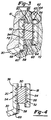
- the rotor 10 is constructed by locating the reinforcement assembly 44 on a core 60 which is in turn positioned relative to one half of a casting mold 61. This is best seen in Figure 3. With the core 60 positioned relative to the mold half 61, the outboard cage 48 is located within the cavity of the mold 61 which defines the outboard braking plate 20. The remaining half 62 of the casting mold is then positioned over the core 60 so as to enclose the reinforcement assembly 44 within the mold cavity. When the mold halves 61 and 62 are closed, the inboard cage 46 is positioned and located by the spacers 56 and 58 within that portion of the mold half 62 which defines the other braking plate 18. The molten material used for forming the cast rotor 10 is then poured into the mold cavity encapsulating the reinforcement assembly 44 during the process. In the interest of clarity, the various mold parting lines 65 are also designated in Figure 3.
- the assembly 44 is formed with or constructed on the core 60 itself.
- the core 60 includes radially extending portions 63 which correspond to the cooling passages 42 of the rotor 10.
- the ribs 50 are formed on the core 60 and are actually positioned within these radial portions 63.
- the cages 46 and 48 are attached to the axial edges of the ribs 50.
- each rib 50 is mounted on the core 60 at a location between two of the radial portions 63, in the space which ordinarily defines a vane 40, thus allowing the ribs 50 to replace three of the vanes 40 in the finished rotor 10.
- This embodiment has the benefit of not reducing or obstructing the flow of cooling air across any portion of the braking plates 18 and 20.
- the rotor 10 can be formed without any ribs 50 at all.
- the outboard cage 46 is located by the spacers 58 directly off of the mold half 61 and positioned within those portions which define the outboard plate 20.
- the core 60 is still positioned with respect to mold half 61.
- the inboard cage 46 is located by its spacers 56 off of mold half 62 and positioned within the portion defining in inboard plate 18.
- the ends of the spacers 56 and 58 are provided with locators or feet that contact and rest against those surfaces of the casting molds 61 and 62 defining the mold cavity and, in particular, the plates 18 and 20.
- feet 64 are therefore bent approximately ninety degrees (90°) from the body of the spacers 56 (the body being that portion of the spacers 56 which extends across the rings 52 and keeps the rings 52 spaced apart) generally parallel to the axis 14 of the rotor 10. Bent in this manner, a length of the feet 64 will be in surface-to-surface contact with a corresponding surface length of the casting molds 62.
- the feet 67 of the spacers 58 utilized with the outboard cage 48 operate to position the outboard cage 48 within the mold 61 in a similar manner.
- the feet 67 formed radially outward on the spacers 58 are oriented like the feet 64 discussed above.
- the feet 68 located radially inward on the spacers 58 are angled, relative to the body of the spacers 58, so as to correspond with and, if desired, engage the surface of the core 60 which defines the interconnecting web 30 of the mounting portion 22.
- Providing the feet 64, 67 and 68 as described above, enables the rings 52 and 54 of the reinforcement assembly 44 to be accurately located within the mold cavity relative to the raw casting surfaces of the rotor 10.
- the raw casting After the raw casting has hardened, it is removed and separated from the core 60 and the casting molds 61 and 62.
- the raw casting surfaces of the inboard and outboard friction braking surfaces 34 and 36 are then machined to their appropriate dimensions. With the reinforcement assembly 44 and the rings 52 and 54 cast within the plates 18 and 20 at a known distance from the raw casting surfaces of the friction braking surfaces 34 and 36, machining can be easily controlled to provide proper spacing between the finished surfaces 34 and 36 and the rings 52 and 54 of the reinforcement assembly 44 in the finished rotor 10.
- the finished dimensions are generally shown as dash lines 72 in Figure 3.
Landscapes
- Engineering & Computer Science (AREA)
- General Engineering & Computer Science (AREA)
- Mechanical Engineering (AREA)
- Braking Arrangements (AREA)
Applications Claiming Priority (2)
| Application Number | Priority Date | Filing Date | Title |
|---|---|---|---|
| US987627 | 1992-12-09 | ||
| US07/987,627 US5358080A (en) | 1992-12-09 | 1992-12-09 | Reinforced brake rotor |
Publications (2)
| Publication Number | Publication Date |
|---|---|
| EP0601465A1 true EP0601465A1 (fr) | 1994-06-15 |
| EP0601465B1 EP0601465B1 (fr) | 1996-10-02 |
Family
ID=25533414
Family Applications (1)
| Application Number | Title | Priority Date | Filing Date |
|---|---|---|---|
| EP93119384A Expired - Lifetime EP0601465B1 (fr) | 1992-12-09 | 1993-12-01 | Rotor de frein en matière composite |
Country Status (6)
| Country | Link |
|---|---|
| US (1) | US5358080A (fr) |
| EP (1) | EP0601465B1 (fr) |
| JP (1) | JPH07301263A (fr) |
| CA (1) | CA2110027A1 (fr) |
| DE (1) | DE69305145T2 (fr) |
| MX (1) | MX9307634A (fr) |
Cited By (2)
| Publication number | Priority date | Publication date | Assignee | Title |
|---|---|---|---|---|
| DE10119150C1 (de) * | 2001-04-19 | 2002-11-14 | Buderus Guss | Bremsscheibe |
| WO2007120108A1 (fr) * | 2006-04-19 | 2007-10-25 | Scania Cv Ab (Publ) | Disque de frein et élément métallique |
Families Citing this family (9)
| Publication number | Priority date | Publication date | Assignee | Title |
|---|---|---|---|---|
| IT230648Y1 (it) * | 1993-10-18 | 1999-06-09 | Brembo Spa | Disco di un freno a disco per veicoli in generale e per vetture ad elevate prestazioni in particolare |
| KR100422542B1 (ko) * | 2001-07-12 | 2004-03-11 | 현대자동차주식회사 | 자동차의 디스크 로터 구조 |
| US8210232B2 (en) * | 2007-09-20 | 2012-07-03 | GM Global Technology Operations LLC | Lightweight brake rotor and components with composite materials |
| DE102011101432B4 (de) * | 2011-05-10 | 2015-01-22 | Daimler Ag | Bremsscheibe |
| DE102013002300B3 (de) | 2013-02-08 | 2014-07-17 | Audi Ag | Bremsscheibe für eine Scheibenbremse eines Kraftfahrzeugs |
| US9841072B2 (en) * | 2014-10-02 | 2017-12-12 | Ford Global Technologies, Llc | Damped brake components and methods of manufacturing the same |
| US10197120B2 (en) * | 2014-10-02 | 2019-02-05 | Ford Global Technologies, Llc | Damped brake components and methods of manufacturing the same |
| US10060495B2 (en) * | 2016-09-15 | 2018-08-28 | Ford Global Technologies, Llc | Dry friction damped mechanical and structural metal components and methods of manufacturing the same |
| DE102019112203A1 (de) * | 2019-05-09 | 2020-11-12 | Bayerische Motoren Werke Aktiengesellschaft | Fahrzeugbremsscheibe |
Citations (3)
| Publication number | Priority date | Publication date | Assignee | Title |
|---|---|---|---|---|
| DE6600085U (de) * | 1968-09-24 | 1969-01-02 | Teves A Gmbh | Bremsscheibe |
| DE2458335A1 (de) * | 1974-12-10 | 1976-06-16 | Promat | Bremsscheibe und verfahren zu ihrer herstellung |
| US5004078A (en) * | 1988-11-09 | 1991-04-02 | Aisin Takaoka Co., Ltd. | Ventilated disk and process for making same |
Family Cites Families (15)
| Publication number | Priority date | Publication date | Assignee | Title |
|---|---|---|---|---|
| US2603316A (en) * | 1952-07-15 | Brake rotor | ||
| GB566951A (en) * | 1943-04-06 | 1945-01-22 | Dunlop Rubber Co | Improvements in or relating to brake, clutch and like mechanism, and devices for usetherewith |
| US2477500A (en) * | 1943-11-05 | 1949-07-26 | American Steel Foundries | Rotor |
| US2769512A (en) * | 1951-11-02 | 1956-11-06 | American Steel Foundries | Brake rotor |
| US2844229A (en) * | 1955-03-31 | 1958-07-22 | Marshall G Whitfield | Wire-wound brake drum or disc |
| DE1425317A1 (de) * | 1963-04-18 | 1968-10-24 | Licentia Gmbh | Ringfoermiger und freitragender Bremskoerper aus Reibmaterial |
| US3483953A (en) * | 1968-03-29 | 1969-12-16 | Bendix Corp | Disc element construction for disc brake |
| US3730304A (en) * | 1971-05-26 | 1973-05-01 | Budd Co | Fabricated ring for a brake disk |
| US3726374A (en) * | 1971-06-02 | 1973-04-10 | Goodrich Co B F | Circular segmented friction member for brake or clutch |
| US4212376A (en) * | 1978-10-11 | 1980-07-15 | The B. F. Goodrich Company | Caliper brake rotor |
| GB8615874D0 (en) * | 1986-06-28 | 1986-08-06 | Automotive Prod Plc | Friction material & carrier plate assembly |
| GB8730164D0 (en) * | 1987-12-24 | 1988-02-03 | Automotive Prod Plc | Friction facing material & carrier assembly |
| US5184663A (en) * | 1988-06-14 | 1993-02-09 | Aisin Takaoka Co., Ltd. | Ventilated disk and process for making same |
| US4858731A (en) * | 1988-07-14 | 1989-08-22 | The Budd Company | Composite brake drum |
| FR2675221B1 (fr) * | 1991-04-09 | 1993-06-11 | Renault Vehicules Ind | Disque de frein formant moyeu tournant. |
-
1992
- 1992-12-09 US US07/987,627 patent/US5358080A/en not_active Expired - Lifetime
-
1993
- 1993-11-25 CA CA002110027A patent/CA2110027A1/fr not_active Abandoned
- 1993-12-01 EP EP93119384A patent/EP0601465B1/fr not_active Expired - Lifetime
- 1993-12-01 DE DE69305145T patent/DE69305145T2/de not_active Expired - Fee Related
- 1993-12-03 MX MX9307634A patent/MX9307634A/es unknown
- 1993-12-09 JP JP5340777A patent/JPH07301263A/ja active Pending
Patent Citations (3)
| Publication number | Priority date | Publication date | Assignee | Title |
|---|---|---|---|---|
| DE6600085U (de) * | 1968-09-24 | 1969-01-02 | Teves A Gmbh | Bremsscheibe |
| DE2458335A1 (de) * | 1974-12-10 | 1976-06-16 | Promat | Bremsscheibe und verfahren zu ihrer herstellung |
| US5004078A (en) * | 1988-11-09 | 1991-04-02 | Aisin Takaoka Co., Ltd. | Ventilated disk and process for making same |
Cited By (2)
| Publication number | Priority date | Publication date | Assignee | Title |
|---|---|---|---|---|
| DE10119150C1 (de) * | 2001-04-19 | 2002-11-14 | Buderus Guss | Bremsscheibe |
| WO2007120108A1 (fr) * | 2006-04-19 | 2007-10-25 | Scania Cv Ab (Publ) | Disque de frein et élément métallique |
Also Published As
| Publication number | Publication date |
|---|---|
| EP0601465B1 (fr) | 1996-10-02 |
| JPH07301263A (ja) | 1995-11-14 |
| DE69305145D1 (de) | 1996-11-07 |
| CA2110027A1 (fr) | 1994-06-10 |
| US5358080A (en) | 1994-10-25 |
| MX9307634A (es) | 1994-06-30 |
| DE69305145T2 (de) | 1997-04-03 |
Similar Documents
| Publication | Publication Date | Title |
|---|---|---|
| EP0601465B1 (fr) | Rotor de frein en matière composite | |
| US5501306A (en) | Brake rotor with a heat-resistant ceramic coating | |
| EP1448399B2 (fr) | Support de roue pour vehicules a freins a disque | |
| JP2003526058A (ja) | デイスクブレーキ用ベンチレーテッドデイスク | |
| CN109210110B (zh) | 高性能制动盘转子 | |
| EP3495684B1 (fr) | Disque de frein destiné à un dispositif de frein à disque d'un véhicule automobile | |
| US20080010806A1 (en) | Method and tools for the production of a braking band for a brake disk | |
| CA2637784A1 (fr) | Disque de frein ferroviaire | |
| US7234572B2 (en) | Braking band for a brake disk | |
| EP2980436B1 (fr) | Disque pour freins à disque et son procédé de fabrication | |
| US6962242B2 (en) | Brake rotor | |
| EP3702636B1 (fr) | Ensemble rotor pour un système de frein à disque | |
| JP2000205313A (ja) | ブレ―キの回転体/ドラムおよびその製作法 | |
| JPH0113941B2 (fr) | ||
| EP3339672B1 (fr) | Disque de frein et son procédé de fabrication | |
| CN111140610A (zh) | 浮动式复合制动盘 | |
| JPS60155020A (ja) | ブレーキドラムの製造方法 | |
| JPS6358295B2 (fr) | ||
| JPS60578B2 (ja) | ブレ−キデイスク | |
| CN118698368A (zh) | 一种转子叶轮加工方法及转子叶轮 | |
| JPH0340446Y2 (fr) | ||
| WO2025109428A1 (fr) | Disque de frein pourvu d'une pluralité d'éléments aérodynamiques pour développer un effet de ventilation | |
| JPH037059Y2 (fr) | ||
| JPH11303908A (ja) | ブレーキローター |
Legal Events
| Date | Code | Title | Description |
|---|---|---|---|
| PUAI | Public reference made under article 153(3) epc to a published international application that has entered the european phase |
Free format text: ORIGINAL CODE: 0009012 |
|
| AK | Designated contracting states |
Kind code of ref document: A1 Designated state(s): DE GB IT SE |
|
| 17P | Request for examination filed |
Effective date: 19940805 |
|
| 17Q | First examination report despatched |
Effective date: 19950425 |
|
| GRAG | Despatch of communication of intention to grant |
Free format text: ORIGINAL CODE: EPIDOS AGRA |
|
| GRAH | Despatch of communication of intention to grant a patent |
Free format text: ORIGINAL CODE: EPIDOS IGRA |
|
| GRAH | Despatch of communication of intention to grant a patent |
Free format text: ORIGINAL CODE: EPIDOS IGRA |
|
| GRAA | (expected) grant |
Free format text: ORIGINAL CODE: 0009210 |
|
| AK | Designated contracting states |
Kind code of ref document: B1 Designated state(s): DE GB IT SE |
|
| PG25 | Lapsed in a contracting state [announced via postgrant information from national office to epo] |
Ref country code: IT Free format text: LAPSE BECAUSE OF FAILURE TO SUBMIT A TRANSLATION OF THE DESCRIPTION OR TO PAY THE FEE WITHIN THE PRE;WARNING: LAPSES OF ITALIAN PATENTS WITH EFFECTIVE DATE BEFORE 2007 MAY HAVE OCCURRED AT ANY TIME BEFORE 2007. THE CORRECT EFFECTIVE DATE MAY BE DIFFERENT FROM THE ONE RECORDED.SCRIBED TIME-LIMIT Effective date: 19961002 |
|
| REF | Corresponds to: |
Ref document number: 69305145 Country of ref document: DE Date of ref document: 19961107 |
|
| PG25 | Lapsed in a contracting state [announced via postgrant information from national office to epo] |
Ref country code: SE Effective date: 19970102 |
|
| RAP2 | Party data changed (patent owner data changed or rights of a patent transferred) |
Owner name: ROBERT BOSCH TECHNOLOGY CORPORATION |
|
| PGFP | Annual fee paid to national office [announced via postgrant information from national office to epo] |
Ref country code: DE Payment date: 19970528 Year of fee payment: 4 |
|
| PLBE | No opposition filed within time limit |
Free format text: ORIGINAL CODE: 0009261 |
|
| STAA | Information on the status of an ep patent application or granted ep patent |
Free format text: STATUS: NO OPPOSITION FILED WITHIN TIME LIMIT |
|
| 26N | No opposition filed | ||
| PG25 | Lapsed in a contracting state [announced via postgrant information from national office to epo] |
Ref country code: GB Free format text: LAPSE BECAUSE OF NON-PAYMENT OF DUE FEES Effective date: 19971201 |
|
| GBPC | Gb: european patent ceased through non-payment of renewal fee |
Effective date: 19971201 |
|
| PG25 | Lapsed in a contracting state [announced via postgrant information from national office to epo] |
Ref country code: DE Free format text: LAPSE BECAUSE OF NON-PAYMENT OF DUE FEES Effective date: 19980901 |