EP0601552A1 - Cafetière électrique - Google Patents
Cafetière électrique Download PDFInfo
- Publication number
- EP0601552A1 EP0601552A1 EP93119739A EP93119739A EP0601552A1 EP 0601552 A1 EP0601552 A1 EP 0601552A1 EP 93119739 A EP93119739 A EP 93119739A EP 93119739 A EP93119739 A EP 93119739A EP 0601552 A1 EP0601552 A1 EP 0601552A1
- Authority
- EP
- European Patent Office
- Prior art keywords
- filter cup
- wall
- water container
- coffee machine
- contour
- Prior art date
- Legal status (The legal status is an assumption and is not a legal conclusion. Google has not performed a legal analysis and makes no representation as to the accuracy of the status listed.)
- Granted
Links
- XLYOFNOQVPJJNP-UHFFFAOYSA-N water Substances O XLYOFNOQVPJJNP-UHFFFAOYSA-N 0.000 claims abstract description 36
- 230000000284 resting effect Effects 0.000 claims 1
- 238000004519 manufacturing process Methods 0.000 description 5
- 238000007789 sealing Methods 0.000 description 2
- 230000015572 biosynthetic process Effects 0.000 description 1
Images


Classifications
-
- A—HUMAN NECESSITIES
- A47—FURNITURE; DOMESTIC ARTICLES OR APPLIANCES; COFFEE MILLS; SPICE MILLS; SUCTION CLEANERS IN GENERAL
- A47J—KITCHEN EQUIPMENT; COFFEE MILLS; SPICE MILLS; APPARATUS FOR MAKING BEVERAGES
- A47J31/00—Apparatus for making beverages
- A47J31/44—Parts or details or accessories of beverage-making apparatus
- A47J31/4403—Constructional details
- A47J31/446—Filter holding means; Attachment of filters to beverage-making apparatus
Definitions
- the invention relates to an electric coffee machine with a filter cup that can be inserted into a space defined by a water container and has an outer contour that tapers downward in a substantially conical manner.
- the basic idea of the invention is to make wall sections of the water container so adapted to the outer contour of the filter cup that the latter sits positively in the water container in the correct position.
- the filter cup can be wholly or only partially surrounded by the wall sections of the water container that are matched to its outer contour.
- the coffee drain of the filter cup is liquid-tight separated from the water in the water tank.
- the filter cup has a handle on a front side, for example, according to a preferred development of the invention, the filter cup in the area of the wall section adjoining its bottom and the wall section of the water container which is adapted to it each have cooperating centering means which self-center the filter cup in the direction of the Water container cause defined space, so that in particular the handle comes to lie directly forward.
- the outer wall of the filter cup starting from a substantially flat cup base, has an oval, in particular elliptical, cross-sectional contour which gradually changes into a circular cross-sectional contour in the direction of the upper edge of the filter cup.
- the front thereof may be desirable to have the front thereof partially protrude from a front wall of the water tank.
- said front wall has a preferred one Formation of an opening opening upwards with a parabolic contour.
- this front part of the filter cup i. H. whose outer wall is form-fitting with the parabolic edge of the cutout in the front wall of the water tank.
- Further centering means can be formed by a groove in the area of the rear wall of the filter cup, this groove running in the direction of a surface line of the filter cup and interacting with a corresponding knob on the wall of the water container adjoining it.
- the described form-fitting seat of the filter cup in the space defined by the water container advantageously enables a compact structure and cost-effective production of the electric coffee machine.
- the preferably provided centering means advantageously ensures that the filter cup assumes the correct fit in every case.
- a water container 4 is provided above a base 5 with an oval, in particular elliptical, outer contour.
- the water tank 4 is enclosed by a front wall 3 and a rear wall 9.
- the front wall 3 and an intermediate wall 8 form a receptacle or a seat for a filter cup, not shown in FIG. 1, which can be inserted into this receptacle from above.
- the front wall 3 is located above a recess projecting into the lower part of the water container, into which the carafe (not shown) can be partially adjusted. In addition, the front wall 3 is offset from the front edge of the base 5 to the rear.
- the lower section 8 'of the intermediate wall 8 and the contour of the inner part 3 of the front wall 3 is elliptical, whereas the contour of the intermediate wall 8 is circular in its upper section with a radius R 1.
- the outer contour of the front wall 3 has a larger radius of curvature R2> R1.
- the filter cup seat has a lower opening E with an oval, in particular elliptical, contour, as clearly shown in FIG.
- the section shown in FIG. 2 through the space defined by the water tank 4 along the section line II-II in FIG. 1 clearly shows the essentially conically tapering shape of that of the through the intermediate wall 8, 8 'and the inner part 3' of the front wall 3 formed filter cup seat.
- the filter cup 2 is shown in its correct seat in this receptacle with dashed lines.
- the front wall 3 is cut obliquely along a sectional plane, so that the filter cup 2 with the upper part of its front wall 16 looks out of this cutout 6 to the front.
- this cutout 6 is cut out along an oblique cutting plane, so that an approximately parabolic edge results. (Fig. 6).
- the outer wall of the filter cup 2 is adapted to the course of the inner surfaces of the intermediate wall 8, 8 'and the front wall 3', so that the filter cup sits in a form-fitting manner.
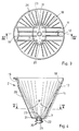
- the filter cup 2 is explained in more detail below with reference to FIGS. 3 to 5.
- the filter cup 2 is shown in a top view in FIG.
- the contour of the upper section 18 of the filter cup wall is essentially circular, but has a recessed grip 19 on the front of the filter cup. The edge bulges outward somewhat at this point.
- a groove 11 running along a surface line, which is molded in from the outside and which has an opening 12 to the inside of the filter cup 2.
- the contour of this wall section 18 ' is oval, in particular elliptical, so that the outer dimensions of the filter cup 2 correspond to the dimensions of the filter cup seat formed by the intermediate wall 8, 8' and the front wall 3 in the space of Water tank 4 is adapted positively.
- the bottom 7 is essentially flat and has in its center a valve 20 which opens under mechanical pressure from the lid of the coffee carafe and of which a valve member 23 and a sealing ring 21 can be seen.
- the bottom 7 is elliptical in plan view and does not protrude beyond the wall section 18 '.
- ribs 26 can be provided on the inner surface of the filter cup wall 18, 18 '.
- FIG. 4 represents a section along the section line IV-IV in FIG.
- the aforementioned pressure valve 20 consists of a plunger 25 biased by a coil spring 22, which at its other end, the is located within the filter cup, has a valve member 23 which seals against a sealing ring 21 serving as a valve seat.
- FIG. 5 shows a representation of a section along the section line V-V in FIG. 4.
- FIG. 6 finally shows the preferred embodiment of the coffee machine according to the invention in a perspective front view, the coffee carafe and the lid being omitted.
- FIG. 6 shows particularly clearly that the front upper part of the filter cup 2 looks forward from the cutout 6 formed in the front wall 3, the parabolic edge of the cutout 6 being form-fitting with the outer wall of the filter cup 2.
- the preferred oval or elliptical contour of the filter cup wall described in the drawing in the region of the bottom and the receptacle surrounding this wall in the space of the water container 4 is not the only possible shape of the filter cup and the wall areas adapted to it in a form-fitting manner.
- the filter cup and the shape of the wall regions surrounding it can also be designed in the shape of a circular cone, in which case the centering is given on its own.
- the correct fit of the filter cup with the recessed handle facing forward can then be brought about, for example, by the interacting groove 11 and the knob 10 on the intermediate wall 8.
- the filter cup sits in a form-fitting manner in wall sections of the space defined by the water container, which results in a compact structure and an inexpensive manufacture of the filter machine.
Landscapes
- Engineering & Computer Science (AREA)
- Food Science & Technology (AREA)
- Apparatus For Making Beverages (AREA)
Applications Claiming Priority (2)
| Application Number | Priority Date | Filing Date | Title |
|---|---|---|---|
| DE4241615 | 1992-12-10 | ||
| DE4241615A DE4241615A1 (de) | 1992-12-10 | 1992-12-10 | Elektrische Kaffeemaschine |
Publications (2)
| Publication Number | Publication Date |
|---|---|
| EP0601552A1 true EP0601552A1 (fr) | 1994-06-15 |
| EP0601552B1 EP0601552B1 (fr) | 1997-04-02 |
Family
ID=6474890
Family Applications (1)
| Application Number | Title | Priority Date | Filing Date |
|---|---|---|---|
| EP93119739A Expired - Lifetime EP0601552B1 (fr) | 1992-12-10 | 1993-12-08 | Cafetière électrique |
Country Status (2)
| Country | Link |
|---|---|
| EP (1) | EP0601552B1 (fr) |
| DE (2) | DE4241615A1 (fr) |
Families Citing this family (1)
| Publication number | Priority date | Publication date | Assignee | Title |
|---|---|---|---|---|
| DE10335824B4 (de) * | 2003-08-05 | 2013-05-29 | BSH Bosch und Siemens Hausgeräte GmbH | Brühgetränkemaschine |
Citations (6)
| Publication number | Priority date | Publication date | Assignee | Title |
|---|---|---|---|---|
| DE2605957A1 (de) * | 1976-02-14 | 1977-08-25 | Wigo Widmann Soehne Gottlob | Elektrische kaffeemaschine mit einem kaffeefilter |
| DE3104542A1 (de) * | 1981-02-09 | 1982-08-26 | Peter 8101 Wallgau Florjancic | Kaffeemaschine |
| DE3112231A1 (de) * | 1981-03-27 | 1982-10-28 | Süddeutsche Elektro-Hausgeräte GmbH & Co KG, 8000 München | Elektrisches geraet zum herstellen heisser getraenke |
| DE8810770U1 (de) * | 1988-08-26 | 1988-10-13 | A. Severin & Co Gmbh, 5768 Sundern | Vorrichtung zum Aufbrühen von Getränken |
| DE3938446C1 (fr) * | 1989-11-18 | 1991-04-18 | Melitta Haushaltsprodukte Gmbh & Co Kg, 4950 Minden, De | |
| DE9106584U1 (de) * | 1991-05-29 | 1991-07-18 | Braun Ag, 6000 Frankfurt | Getränkebereitungsmaschine |
Family Cites Families (2)
| Publication number | Priority date | Publication date | Assignee | Title |
|---|---|---|---|---|
| DE7508456U (fr) * | 1975-03-18 | 1976-09-23 | Philips Patentverwaltung Gmbh, 2000 Hamburg | |
| GB2229354A (en) * | 1989-01-26 | 1990-09-26 | Russell Hobbs Tower Limited | Filter coffee machine |
-
1992
- 1992-12-10 DE DE4241615A patent/DE4241615A1/de not_active Withdrawn
-
1993
- 1993-12-08 DE DE59306026T patent/DE59306026D1/de not_active Expired - Fee Related
- 1993-12-08 EP EP93119739A patent/EP0601552B1/fr not_active Expired - Lifetime
Patent Citations (6)
| Publication number | Priority date | Publication date | Assignee | Title |
|---|---|---|---|---|
| DE2605957A1 (de) * | 1976-02-14 | 1977-08-25 | Wigo Widmann Soehne Gottlob | Elektrische kaffeemaschine mit einem kaffeefilter |
| DE3104542A1 (de) * | 1981-02-09 | 1982-08-26 | Peter 8101 Wallgau Florjancic | Kaffeemaschine |
| DE3112231A1 (de) * | 1981-03-27 | 1982-10-28 | Süddeutsche Elektro-Hausgeräte GmbH & Co KG, 8000 München | Elektrisches geraet zum herstellen heisser getraenke |
| DE8810770U1 (de) * | 1988-08-26 | 1988-10-13 | A. Severin & Co Gmbh, 5768 Sundern | Vorrichtung zum Aufbrühen von Getränken |
| DE3938446C1 (fr) * | 1989-11-18 | 1991-04-18 | Melitta Haushaltsprodukte Gmbh & Co Kg, 4950 Minden, De | |
| DE9106584U1 (de) * | 1991-05-29 | 1991-07-18 | Braun Ag, 6000 Frankfurt | Getränkebereitungsmaschine |
Also Published As
| Publication number | Publication date |
|---|---|
| DE4241615A1 (de) | 1994-06-16 |
| DE59306026D1 (de) | 1997-05-07 |
| EP0601552B1 (fr) | 1997-04-02 |
Similar Documents
| Publication | Publication Date | Title |
|---|---|---|
| DE3018908C2 (fr) | ||
| DE2752733C2 (de) | Gemahlenen Kaffee enthaltende Patrone für eine Getränkemaschine | |
| EP1793933B1 (fr) | Utilisation d'un reservoir d'ecoulement pour pistolet a peinture | |
| DE102019103328B4 (de) | Relais | |
| DE60215010T3 (de) | Verschlussvorrichtung und behälter mit einer solchen vorrichtung | |
| DE19983651B4 (de) | Fluidsteuerung | |
| DE69501184T2 (de) | Anordnung zum Verbinden an einem Pol | |
| DE4431006A1 (de) | Elektrische Anschlußklemme | |
| EP0419790A2 (fr) | Fermeture en matière plastique pour bouches de récipients et de bouteilles | |
| DE3853803T2 (de) | Selbsttropfenfangender Behälter. | |
| EP1131222B1 (fr) | Bouchon pour le reservoir a carburant d'un vehicule automobile | |
| EP4188574B1 (fr) | Réservoir d'eau pourvu d'une cartouche filtre | |
| DE4425028A1 (de) | Scheinwerfer für Fahrzeuge | |
| DE3415442A1 (de) | Scheinwerfer, insbesondere fuer ein kraftfahrzeug | |
| DE29812483U1 (de) | Filter für Flüssigkeiten | |
| DE69728479T2 (de) | Gesockelte elektrische Lampe | |
| DE60026820T2 (de) | Ventil für abgasrückführung | |
| DE69231009T2 (de) | Lampenfassung und daran montierte Anschlussklemme | |
| EP0601552B1 (fr) | Cafetière électrique | |
| EP4400756B1 (fr) | Connecteur de ligne à faible résistance à l'écoulement | |
| DE9209268U1 (de) | Leuchte für Fahrzeuge | |
| DE3610460A1 (de) | Elektrischer druckschalter | |
| DE10224245A1 (de) | Absperrventil für einen druckbeaufschlagten Behälter sowie Behälter | |
| DE3134613A1 (de) | Elektromagnetisches umschaltventil | |
| DE3132346A1 (de) | Fuellstandsmessvorrichtung bei einem kraftstofftank |
Legal Events
| Date | Code | Title | Description |
|---|---|---|---|
| PUAI | Public reference made under article 153(3) epc to a published international application that has entered the european phase |
Free format text: ORIGINAL CODE: 0009012 |
|
| 17P | Request for examination filed |
Effective date: 19940408 |
|
| AK | Designated contracting states |
Kind code of ref document: A1 Designated state(s): CH DE DK FR IT LI NL SE |
|
| 17Q | First examination report despatched |
Effective date: 19950807 |
|
| GRAG | Despatch of communication of intention to grant |
Free format text: ORIGINAL CODE: EPIDOS AGRA |
|
| GRAH | Despatch of communication of intention to grant a patent |
Free format text: ORIGINAL CODE: EPIDOS IGRA |
|
| GRAH | Despatch of communication of intention to grant a patent |
Free format text: ORIGINAL CODE: EPIDOS IGRA |
|
| GRAA | (expected) grant |
Free format text: ORIGINAL CODE: 0009210 |
|
| AK | Designated contracting states |
Kind code of ref document: B1 Designated state(s): CH DE DK FR IT LI NL SE |
|
| PG25 | Lapsed in a contracting state [announced via postgrant information from national office to epo] |
Ref country code: NL Effective date: 19970402 Ref country code: IT Free format text: LAPSE BECAUSE OF FAILURE TO SUBMIT A TRANSLATION OF THE DESCRIPTION OR TO PAY THE FEE WITHIN THE PRE;WARNING: LAPSES OF ITALIAN PATENTS WITH EFFECTIVE DATE BEFORE 2007 MAY HAVE OCCURRED AT ANY TIME BEFORE 2007. THE CORRECT EFFECTIVE DATE MAY BE DIFFERENT FROM THE ONE RECORDED.SCRIBED TIME-LIMIT Effective date: 19970402 Ref country code: DK Effective date: 19970402 |
|
| REG | Reference to a national code |
Ref country code: CH Ref legal event code: NV Representative=s name: NOVATOR AG Ref country code: CH Ref legal event code: EP |
|
| RAP4 | Party data changed (patent owner data changed or rights of a patent transferred) |
Owner name: EMIDE-METALLINDUSTRIE GEBR. STREICHER |
|
| REF | Corresponds to: |
Ref document number: 59306026 Country of ref document: DE Date of ref document: 19970507 |
|
| ET | Fr: translation filed | ||
| NLV1 | Nl: lapsed or annulled due to failure to fulfill the requirements of art. 29p and 29m of the patents act | ||
| PLBE | No opposition filed within time limit |
Free format text: ORIGINAL CODE: 0009261 |
|
| STAA | Information on the status of an ep patent application or granted ep patent |
Free format text: STATUS: NO OPPOSITION FILED WITHIN TIME LIMIT |
|
| 26N | No opposition filed | ||
| PGFP | Annual fee paid to national office [announced via postgrant information from national office to epo] |
Ref country code: SE Payment date: 20011218 Year of fee payment: 9 |
|
| PGFP | Annual fee paid to national office [announced via postgrant information from national office to epo] |
Ref country code: FR Payment date: 20011221 Year of fee payment: 9 |
|
| PGFP | Annual fee paid to national office [announced via postgrant information from national office to epo] |
Ref country code: CH Payment date: 20011224 Year of fee payment: 9 |
|
| PGFP | Annual fee paid to national office [announced via postgrant information from national office to epo] |
Ref country code: DE Payment date: 20011228 Year of fee payment: 9 |
|
| PG25 | Lapsed in a contracting state [announced via postgrant information from national office to epo] |
Ref country code: SE Free format text: LAPSE BECAUSE OF NON-PAYMENT OF DUE FEES Effective date: 20021209 |
|
| PG25 | Lapsed in a contracting state [announced via postgrant information from national office to epo] |
Ref country code: LI Free format text: LAPSE BECAUSE OF NON-PAYMENT OF DUE FEES Effective date: 20021231 Ref country code: CH Free format text: LAPSE BECAUSE OF NON-PAYMENT OF DUE FEES Effective date: 20021231 |
|
| PG25 | Lapsed in a contracting state [announced via postgrant information from national office to epo] |
Ref country code: DE Free format text: LAPSE BECAUSE OF NON-PAYMENT OF DUE FEES Effective date: 20030701 |
|
| EUG | Se: european patent has lapsed | ||
| REG | Reference to a national code |
Ref country code: CH Ref legal event code: PL |
|
| PG25 | Lapsed in a contracting state [announced via postgrant information from national office to epo] |
Ref country code: FR Free format text: LAPSE BECAUSE OF NON-PAYMENT OF DUE FEES Effective date: 20030901 |
|
| REG | Reference to a national code |
Ref country code: FR Ref legal event code: ST |