EP0601588A1 - Vierradlenkungssystem für ein Fahrzeug - Google Patents
Vierradlenkungssystem für ein Fahrzeug Download PDFInfo
- Publication number
- EP0601588A1 EP0601588A1 EP93119899A EP93119899A EP0601588A1 EP 0601588 A1 EP0601588 A1 EP 0601588A1 EP 93119899 A EP93119899 A EP 93119899A EP 93119899 A EP93119899 A EP 93119899A EP 0601588 A1 EP0601588 A1 EP 0601588A1
- Authority
- EP
- European Patent Office
- Prior art keywords
- vehicle
- term
- vehicle speed
- correction
- value
- Prior art date
- Legal status (The legal status is an assumption and is not a legal conclusion. Google has not performed a legal analysis and makes no representation as to the accuracy of the status listed.)
- Granted
Links
- 230000004044 response Effects 0.000 claims abstract description 10
- 230000007246 mechanism Effects 0.000 description 12
- 230000004048 modification Effects 0.000 description 11
- 238000012986 modification Methods 0.000 description 11
- 230000002159 abnormal effect Effects 0.000 description 6
- 230000008859 change Effects 0.000 description 4
- 238000010586 diagram Methods 0.000 description 1
- 230000006872 improvement Effects 0.000 description 1
- 230000007935 neutral effect Effects 0.000 description 1
Images

Classifications
-
- B—PERFORMING OPERATIONS; TRANSPORTING
- B62—LAND VEHICLES FOR TRAVELLING OTHERWISE THAN ON RAILS
- B62D—MOTOR VEHICLES; TRAILERS
- B62D7/00—Steering linkage; Stub axles or their mountings
- B62D7/06—Steering linkage; Stub axles or their mountings for individually-pivoted wheels, e.g. on king-pins
- B62D7/14—Steering linkage; Stub axles or their mountings for individually-pivoted wheels, e.g. on king-pins the pivotal axes being situated in more than one plane transverse to the longitudinal centre line of the vehicle, e.g. all-wheel steering
- B62D7/15—Steering linkage; Stub axles or their mountings for individually-pivoted wheels, e.g. on king-pins the pivotal axes being situated in more than one plane transverse to the longitudinal centre line of the vehicle, e.g. all-wheel steering characterised by means varying the ratio between the steering angles of the steered wheels
- B62D7/159—Steering linkage; Stub axles or their mountings for individually-pivoted wheels, e.g. on king-pins the pivotal axes being situated in more than one plane transverse to the longitudinal centre line of the vehicle, e.g. all-wheel steering characterised by means varying the ratio between the steering angles of the steered wheels characterised by computing methods or stabilisation processes or systems, e.g. responding to yaw rate, lateral wind, load, road condition
-
- B—PERFORMING OPERATIONS; TRANSPORTING
- B62—LAND VEHICLES FOR TRAVELLING OTHERWISE THAN ON RAILS
- B62D—MOTOR VEHICLES; TRAILERS
- B62D7/00—Steering linkage; Stub axles or their mountings
Definitions
- This invention relates to a four-wheel steering system for a vehicle, and more particularly to a four-wheel steering system in which a target value for controlling turning of the rear wheels in response to turning of the front wheels is determined taking into account a value representing a running state of the vehicle other than the vehicle speed such as the turning angle of the front wheels, the yaw rate or the like. (Such a value will be referred to as "a running state value”, hereinbelow.)
- the rear wheels are generally turned in the direction opposite to the front wheel turning direction (the reverse phase) in a low vehicle speed range in order to improve heading of the vehicle and in the same direction as the front wheel turning direction (the same phase) in a high vehicle speed range in order to improve the running stability.
- a target value for controlling turning of the rear wheels in response to turning of the front wheels e.g., a target rear wheel turning angle or the ratio of the rear wheel turning angle to the front wheel turning angle
- a target value for controlling turning of the rear wheels in response to turning of the front wheels is determined by addition and subtraction of a base term which is determined according to the vehicle speed and a plurality of correction terms which are determined on the basis of running state values other than the vehicle speed such as the front wheel turning angle, the front wheel turning speed, and the yaw rate, thereby improving the heading and directional stability of the vehicle during turning in harmony with each other.
- Each of the correction terms is a product of a function of the corresponding running state value and a control gain, and the control gain is determined according to the vehicle speed.
- the control gain is set to be 0 in a low vehicle speed range and to be a positive constant in a high vehicle speed range.
- the conventional four-wheel steering system involves the following problem. That is, when the vehicle is sharply decelerated during turning, the base term changes to the reverse phase side and the yaw rate correction term changes to 0 and accordingly, the rear wheel turning angle changes from the same phase to the reverse phase, which causes an oversteering state and deteriorates the running stability.
- This problem may be overcome by fixing the target value for controlling turning of the rear wheels when the vehicle is sharply decelerated during turning.
- this approach is disadvantageous in that since the running state values are all ignored when the target value is fixed, fine rear wheel turning control cannot be realized.
- the rear wheel turning control is carried out on the basis of a target value which is on the reverse phase side of the target value which is determined taking into account the yaw rate, and accordingly, behavior of the vehicle cannot be sufficiently controlled.
- the rear wheel turning control is carried out on the basis of a target value which is on the same phase side of the target value which is determined taking into account the front wheel turning angle and the front wheel turning speed, and accordingly, the vehicle cannot be turned sufficiently quickly.
- the primary object of the present invention is to provide a four-wheel steering system for a vehicle in which fine rear wheel turning control can be realized with the stability and the heading performance of the vehicle harmonized with each other.
- the four-wheel steering system in accordance with the present invention comprises a target value determining means which determines a target value for controlling turning of the rear wheels in response to turning of the front wheels by adding and subtracting a plurality of correction terms which are determined on the basis of running state values other than the vehicle speed to and from a base term which is determined according to the vehicle speed, the base term being set according to the vehicle speed so that the rear wheels are turned in the reverse phase in a low vehicle speed range and in the same phase in a high vehicle speed range, and each of said correction terms being a product of a function of the corresponding running state value and a control gain determined according to the vehicle speed, and characterized by having a determining means which determines that the vehicle is making a sharp deceleration and a correction means which causes the target value determining means to fix the base term and the control gains of at least one of the correction terms to respective predetermined values and to determine the target value on the basis of the base term and the correction terms thus obtained when the determining means determines that the vehicle is making a sharp
- said correction terms which are determined on the basis of running state values other than the vehicle speed includes a yaw-rate-based correction term, a front-wheel-turning-angle-based correction term and a front-wheel-turning-speed-based correction term respectively having the yaw rate, the front wheel turning angle and the front wheel turning speed as the running state values
- the control gain of the yaw-rate-based correction term is set to be 0 in a low vehicle speed range, to be a positive constant value in a middle vehicle speed range and to be a positive constant value in a high vehicle speed range
- the control gain of the front-wheel-turning-angle-based correction term is set to be a positive constant value in the low vehicle speed range, to be 0 in the middle vehicle speed range and to be a positive constant value in the high vehicle speed range
- the control gain of the front-wheel-turning-speed-based correction term is set to be a positive constant value in the low vehicle speed range, to be 0 in the middle vehicle speed range
- the base term and the control gains may be fixed to the values at the time of determination that the vehicle is making a sharp deceleration during turning, or may be fixed to values somewhat smaller or larger than those at the time of determination that the vehicle is making a sharp deceleration.
- the "target value for controlling turning of the rear wheels” may be a target rear wheel turning angle, a target rear wheel turning angle ratio (the ratio of the rear wheel turning angle to the front wheel turning angle), or the like so long as it is used for controlling turning of the rear wheels.
- the values which changes with the vehicle speed are fixed and the values which depend upon the running state values other than the vehicle speed are not fixed. Accordingly, even if the vehicle speed as detected by the vehicle speed sensor lowers, the target value for controlling turning of the rear wheels cannot be sharply changed from the same phase to the reverse phase, whereby occurrence of an oversteering state can be prevented, and at the same time, since the target value can change with change in the other running state values, the heading performance can be ensured.
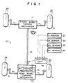
- a four-wheel steering system in accordance with an embodiment of the present invention comprises a front wheel turning mechanism 11 which turns front wheels 1 and 2 of a vehicle, a rear wheel turning mechanism 13 which is mechanically connected to the front wheel turning mechanism 11 by way of a relay shaft 12 and turns rear wheels 3 and 4 in response to turning the front wheels 1 and 2 to a target rear wheel turning angle ⁇ R determined according to a given front wheel turning angle ⁇ F input from the front wheel turning mechanism 11, and a control unit 15 which controls the rear wheel turning mechanism 13 by way of a rear wheel turning angle ratio changing mechanism 14 built in the rear wheel turning mechanism 13.
- the rear wheel turning angle ratio changing mechanism 14 sets and changes the rear wheel turning angle ratio ⁇ S which is the ratio of the rear wheel turning angle ⁇ R to the front wheel turning angle ⁇ F .
- Signals representing the vehicle speed V, the yaw rate ⁇ ', the rear wheel turning angle ratio ⁇ S and the front wheel turning angle ⁇ F are input into the control unit 15 from a vehicle speed sensor 21, a yaw rate sensor 22, a rear wheel turning angle ratio sensor 23 and a front wheel turning angle sensor 24.
- the rear wheel turning angle ratio sensor 23 detects the rear wheel turning angle ratio ⁇ S set by the rear wheel turning angle ratio changing mechanism 14 and the front wheel turning angle sensor 24 detects the front wheel turning angle ⁇ F , for instance, through the rotational angle of the steering shaft of the front wheel turning mechanism 11.
- the control unit 15 calculates the target rear wheel turning angle ratio TG ⁇ S according to the following formula (1).
- TG ⁇ S -G1 ⁇ f1(V) ⁇ S ⁇ St + G2 ⁇ K2( ⁇ F2 ) ⁇ J2(
- the control unit 15 determines the operands, i.e., the terms of the right side of the above formula, on the basis of the vehicle speed V, the yaw rate ⁇ ', the front wheel turning angle ⁇ F and the rate of change ⁇ ' F2 of the front wheel turning angle ⁇ F which is obtained by differentiating the front wheel turning angle ⁇ F .
- the control unit 15 corrects it to a value within the range. Then the control unit 15 calculates the target rear wheel turning angle ⁇ R according to the following formula (2).
- TG ⁇ R ⁇ F ⁇ TG ⁇ S1
- TG ⁇ S1 represents the target rear wheel turning angle ratio TG ⁇ S as it is calculated on the basis of the aforesaid operands or corrected as required.
- the first term of the right side of the formula (1) is a front-wheel-turning-angle-based correction term wherein ⁇ S ⁇ St is a correction value based on the front wheel turning angle ⁇ F .
- the second term is a yaw-rate-based correction term wherein ⁇ S ⁇ YAW is a correction value based on the yaw rate ⁇ '.
- the third term is a front-wheel-turning-speed-based correction term wherein ⁇ S ⁇ StD is a correction value based on the rate of change ⁇ ' F2 .
- the fourth term is a base term based on which the rear wheel turning is controlled according to the vehicle speed V.
- a phase switching control where when the front wheels are turned while the vehicle is running straight, the rear wheels are turned in the direction opposite to the front wheels at the beginning of the turning, thereby improving the heading performance, and then the rear wheels are turned in the same direction as the front wheels as the yaw rate is generated, thereby improving the directional stability, can be performed while the control of the rear wheel turning is basically effected according to the vehicle speed.
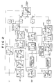
- G1, G2, G3 and G4 in the formula (1) are constants, and the variables in the formula (1) are calculated in the following manner on the basis of the vehicle speed V, the yaw rate ⁇ ' and the front wheel turning angle ⁇ F as shown in Figure 2.
- Variables f1(V), f2(V), f3(V) and f4(V) are vehicle speed sensitive control gains and are respectively calculated according to maps m10, m5, m13 and m1 ( Figure 2) on the basis of the vehicle speed V. According to the maps m10 and m13, the variables f1(V) and f3(V) are 0 in the low and high vehicle speed ranges and are positive constant values in the middle vehicle speed range. According to the map m5, the variable f2(V) is 0 in the low vehicle speed range and are positive constant values in the middle and high vehicle speed ranges.
- the variable f4(V) is of a negative value having a large absolute value in the low vehicle speed range, is increased from a negative value to a positive value as the vehicle speed increases in the middle vehicle speed range and is of a large positive value in the high vehicle speed range.
- the correction value ⁇ S ⁇ St of the first term is derived from the front wheel turning angle ⁇ F in the following manner. That is, the front wheel turning angle ⁇ F is converted into ⁇ F1 according to map m8 which has an offset and then ⁇ F1 is converted into ⁇ F2 according to map mll which has hysteresis. Then the correction value ⁇ S ⁇ St is calculated according to map m9 on the basis of the absolute value of ⁇ F2 (
- the offset of map m8 is for preventing unnecessary control by providing a dead zone near the neutral position of the steering wheel.
- the hysteresis of map mll is for preventing hunting of control.
- the correction value ⁇ S ⁇ St is 0 in the small front wheel turning angle range, is increased with increase of the front wheel turning angle in the middle front wheel turning angle range and is of a positive constant value in the large front wheel turning angle range.
- the correction value ⁇ S ⁇ St is nullified taking that it is an abnormal value.
- the correction value ⁇ S ⁇ YAW of the second term is derived from the yaw rate ⁇ ' in the following manner. That is, the yaw rate ⁇ ' is converted into ⁇ '1 according to map m2 which has an offset and then ⁇ '1 is converted into ⁇ '2 according to map m3 which has hysteresis. Then the correction value ⁇ S ⁇ YAW is calculated according to map m4 on the basis of ⁇ '2.
- the offset of map m2 and the hysteresis of map m3 are for the same reason as for the correction value ⁇ S ⁇ St .
- the correction value ⁇ S ⁇ YAW is proportional to ⁇ '2 in the small yaw rate range and is of a constant value in the middle yaw rate range.
- the correction value ⁇ S ⁇ YAW is nullified taking that it is an abnormal value.
- Variables K2( ⁇ F2 ) of the second term is a front wheel turning angle sensitive control gain and is calculated according to map m6 on the basis of ⁇ F2 obtained from map mll. According to map m6, the variable K2( ⁇ F2 ) is of a value substantially proportional to ⁇ F2 in the small front wheel turning angle range and the rate of increase of the value of the variable K2( ⁇ F2 ) is reduced as the front wheel turning angle increases.
- ) of the second term is a control gain sensitive to the front wheel turning speed and is calculated according to map m7 on the basis of the absolute value
- ) is of a small value in the range where
- Variable ⁇ S ⁇ StD is a correction value sensitive to the front wheel turning speed and is calculated according to map m12 on the basis of the differentiated value ⁇ ' F2 of ⁇ F2 obtained from map mll.
- the variable ⁇ S ⁇ StD is of a value proportional to ⁇ ' F2 in the range where the front wheel turning speed is low, is of a positive constant value in the range where the front wheel turning speed is middle and is 0 in the range where the front wheel turning speed is high taking that it is an abnormal value.
- Variables K3( ⁇ F2 ) of the third term is a front wheel turning angle sensitive control gain and is calculated according to map m14 on the basis of ⁇ F2 obtained from map m11. According to map m14, the variable K3( ⁇ F2 ) is of a value substantially proportional to ⁇ F2 in the small front wheel turning angle range and the rate of increase of the value of the variable K3( ⁇ F2 ) is reduced as the front wheel turning angle increases.
- the target rear wheei turning angle ratio TG ⁇ S is determined by addition and subtraction of the operands obtained by multiplying the constants and the variables for each term of the formula (1), the target rear wheel turning angle ratio TG ⁇ S is of an abnormal value when the result of addition and subtraction is of an abnormal value. Accordingly, when the target rear wheel turning angle ratio TG ⁇ S thus obtained is outside an acceptable range which is set according to the vehicle speed V (represented by hatched portion in map m15), the target rear wheel turning angle ratio TG ⁇ S is corrected to the upper or lower limit of the acceptable range (represented by the broken lines in map m15).
- the solid line in map m15 shows the variable f4(V) shown in map m1.
- the structure shown in Figure 2 forms a target value determining means 31 and the target value determining means 31 is provided in the control unit 15.
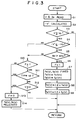
- the target rear wheel turning angle ratio TG ⁇ S determined in the manner described above is corrected according to the flow chart shown in Figure 3 when the vehicle is making a sharp deceleration during turning.
- the vehicle speed V detected by the vehicle speed sensor 21 and the front wheel turning angle ⁇ F detected by the front wheel turning angle sensor 24 are first read (step S1) and then the deceleration of the vehicle -V' is calculated (step S2).
- the deceleration of the vehicle -V' is obtained by dividing the difference between the preceding value and the present value of the vehicle speed V by the cycle time.
- step S3 it is determined whether the vehicle speed V is not lower than a predetermined value Vo, and in step S4, it is determined whether the deceleration of the vehicle -V' is not smaller than a predetermined value -V'o (-V' ⁇ -V'o), and in step S5, it is determined whether the front wheel turning angle ⁇ F is larger than a predetermined value ⁇ Fo .
- flag F is set to 1 in step S6.
- step S7 the vehicle speed sensitive control gains f4(V) and f2(V) of the fourth term (the base term) and the second term (the yaw-rate-based correction term) of the formula (1) are fixed respectively to the values at that time f4(Vn) and f2(Vn).
- the fixed control gains f4(V) and f2(V) are then replaced with the values obtained by multiplying them by 1.2. (steps S8 and S9) Then the flow returns.
- step S3 When it is determined in step S3 that the vehicle speed V is lower than the predetermined value Vo, the flow directly returns.
- step S10 determines whether the flag F is 1.
- step S11 determines whether time is up and it is determined in step S12 whether the vehicle speed is 0.
- step S11 determines whether time is not up and at the same time it is determined in step S12 that the vehicle speed is not 0, the flow immediately returns.
- step S10 When it is determined in step S10 that the flag F is not 1, when it is determined in step S11 that time is up or when it is determined in step S12 that the vehicle speed is 0, the flag F is reset to 0 in step S13 and the fixed control gains f4(V) and f2(V) are released in step S14.
- the target rear wheel turning angle ratio TG ⁇ S is corrected on the basis of the fixed control gains f4(V) and f2(V) in steps S6 to S14. Since the base term is the product of the control gain f4(V) and a constant, the base term is fixed when the control gain f4(V) is fixed.
- the control unit 15 determines the target rear wheel turning angle ratio TG ⁇ S on the basis of the formula (1) and corrects the target rear wheel turning angle ratio TG ⁇ S to be in the acceptable range if necessary. Then the control unit 15 controls the rear wheel turning angle ratio changing mechanism 14 to set the actual rear wheel turning angle ratio ⁇ S to the target rear wheel turning angle ratio TG ⁇ S 1 thus obtained. Then the rear wheel turning mechanism 13 turns the rear wheels to an angle ⁇ R which is the product of the target rear wheel turning angle ratio TG ⁇ S 1 and the front wheel turning angle ⁇ F under feedback control by the control unit 15.
- the target rear wheel turning angle ratio TG ⁇ S is determined by adding and subtracting the correction terms determined on the basis of the running state values other than the vehicle speed, i.e., the front wheel turning angle, the front wheel turning speed and the yaw rate, to and from the base term which is changed according to the vehicle speed, both the heading performance and the stability during turning can be improved.
- the base term (more strictly the control gain f4(V) thereof) and the control gain f2(V) of the yaw-rate-based correction term are fixed in the formula (1). Accordingly, even if the vehicle speed lowers, the target rear wheel turning angle ratio TG ⁇ S cannot be sharply changed from the same phase to the reverse phase, whereby occurrence of an oversteering state can be prevented.
- the target rear wheel turning angle ratio TG ⁇ S changes toward the same phase in response to increase in the yaw rate ⁇ ' or the yaw-rate-based correction value ⁇ S ⁇ YAW , whereby unstable behavior of the vehicle can be prevented.
- control gains f4(V) and f2(V) are fixed to the value 1.2 times the value of these control gains at the time of determination that the vehicle is making a sharp deceleration during turning, that is, the value of these control gains at the time of determination that the vehicle is making a sharp deceleration during turning is corrected toward the same phase, turning of the rear wheels is further corrected toward the same phase and accordingly, unstable behavior of the vehicle can be better prevented.
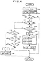
- Figure 4 shows a modification of the flow chart shown in Figure 3 for correcting the target rear wheel turning angle ratio TG ⁇ S .
- step S21 the vehicle speed V and the front wheel turning angle ⁇ F are first read (step S21) and then the deceleration of the vehicle -V' is calculated (step S22) as in the embodiment described above. Then in step S23, it is determined whether the vehicle speed V is not lower than a predetermined value Vo, and in step S24, it is determined whether the deceleration of the vehicle -V' is not smaller than a predetermined value -V'o (-V' ⁇ -V'o), and in step S25, it is determined whether the front wheel turning angle ⁇ F is larger than a predetermined value ⁇ Fo .
- step S26 When the answers to the questions in these steps are all YES, flag F is set to 1 in step S26 and then in step S27, the vehicle speed sensitive control gains f1(V) to f4(V) of the formula (1) are fixed respectively to the values at that time f1(Vn) to f4(Vn).
- the fixed control gain f3(V) of the third term front-wheel-turning-speed-based correction term
- step S28 Then the flow returns.
- step S23 When the answer to the question in step S23 is NO, the flow directly returns.
- step S30 it is determined in step S30 whether the flag F is 1. When it is determined that the flag F is 1, it is then determined in step S31 whether time is up and it is determined in step S32 whether the vehicle speed is 0. When the answers to the questions in steps S31 and S32 are both NO, the flow immediately returns.
- step S30 When the answer to the question in step S30 is NO, or when the answer to the question in step S31 or S32, the flag F is reset to 0 in step S33 and the fixed control gains f1(V) to f4(V) are released in step S34.
- the target rear wheel turning angle ratio TG ⁇ S is corrected on the basis of the fixed control gains f1(V) to f4(V) in steps S26 to S28 and S30 to S34.
- the target rear wheel turning angle ratio TG ⁇ S changes toward the reverse phase in response to increase in the front wheel turning angle and the front wheel turning speed when the steering wheel is turned in the reverse direction while the vehicle is making a sharp deceleration during turning, whereby the heading performance of the vehicle can be improved.
- control gains f3(V) of the front-wheel-turning-speed-based correction term is fixed to the value 1.2 times the value of the control gain at the time of determination that the vehicle is making a sharp deceleration during turning, that is, the value of the control gain at the time of determination that the vehicle is making a sharp deceleration during turning is corrected toward the reverse phase, turning of the rear wheels is further corrected toward the reverse phase and accordingly, the heading performance of the vehicle can be better improved.
- control gains are fixed when the vehicle is making a sharp deceleration during turning, it is preferred that the control gains be fixed when the vehicle is making a sharp deceleration irrespective of whether the vehicle is making a turn so that the target value is corrected both when the vehicle begins to make a sharp deceleration during turning and when the vehicle begins turning while the vehicle is making a sharp deceleration.
- Figure 5 shows another modification of the flow chart shown in Figure 3 for correcting the target rear wheel turning angle ratio TG ⁇ S .
- step S42 When the vehicle speed V is not lower than a predetermined value Vo (e.g., 50 to 60Km/h) (step S41), it is determined in step S42 whether the deceleration of the vehicle -V' is not smaller than a predetermined value -V'o (-V' ⁇ -V'o). When it is determined that the deceleration of the vehicle -V' is not smaller than the predetermined value -V'o (-V' ⁇ -V'o), that is, when it is determined that the vehicle is making a sharp deceleration, flag F is set to 1 in step S42.
- a predetermined value Vo e.g., 50 to 60Km/h
- step S44 the vehicle speed sensitive control gain f4(V) of the fourth term (the base term) of the formula (1) is fixed to the value at that time f4(Vn). Then the constants G2 and G3 of the yaw-rate-based correction term and the front-wheel-turning-speed-based correction term are increased to 1.2 times the normal values. (steps S45 and S46)
- step S47 When it is determined that the deceleration of the vehicle -V' is smaller than the predetermined value -V'o (-V' ⁇ -V'o) in step S42, it is determined in step S47 whether the flag F is 1. When it is determined that the flag F is 1, it is then determined in step S41 whether time is up and it is determined in step S49 whether the vehicle speed is 0. When it is determined in step S48 that time is not up and at the same time it is determined in step S49 that the vehicle speed is not 0, the flow immediately returns.
- step S47 When it is determined in step S47 that the flag F is not 1, when it is determined in step S48 that time is up or when it is determined in step S49 that the vehicle speed is 0, the flag F is reset to 0 in step S50 and the fixed control gain f4(V) is released and the constant G2 and G3 are returned to the normal values. (step S51)
- the vehicle speed signal representing the vehicle speed as detected by the vehicle speed sensor can become very small relative to the actual vehicle speed due to lock of the wheels or the like.
- the control gain f4(V) of the base term greatly changes toward the negative and accordingly, the base term greatly changes toward the negative, whereby turning of the rear wheels are controlled giving weight to the heading performance rather than the directional stability of the vehicle in spite of a high actual vehicle speed, which can result in unstable behavior of the vehicle.
- the yaw-rate-based correction term is a parameter which is added in calculation of the target rear wheel turning angle ratio TG ⁇ S and is used in order to improve the directional stability of the vehicle and on the other hand, the front-wheel-turning-angle-based correction term and the front-wheel-turning-speed-based correction term are parameters which are subtracted in calculation of the target rear wheel turning angle ratio TG ⁇ S and is used in order to improve the heading performance of the vehicle.
- the front wheel turning angle signal and the front wheel turning speed signal are feedforward type signals as well as the vehicle speed signal and accordingly are immediately reflected to determination of the target rear wheel turning angle ratio TG ⁇ S .
- the yaw rate signal is a feedback type signal and is reflected to determination of the target rear wheel turning angle ratio TG ⁇ S with a certain delay. Accordingly, the front wheel turning angle ⁇ F and the front wheel turning speed ⁇ ' F2 contribute to determination of the value of the target rear wheel turning angle ratio TG ⁇ S more than the yaw rate ⁇ ' immediately after beginning of the sharp deceleration and then the yaw rate ⁇ ' comes to largely contribute to determination of the same.
- the heading performance can be improved immediately after beginning of the sharp deceleration and thereafter the directional stability of the vehicle can be improved.
- the walker can be easily cleared due to the improvement in the heading performance immediately after beginning of the sharp deceleration and the stability of the vehicle thereafter can be ensured.
- the constant G3 of the front-wheel-turning-speed-based correction term which quickly responses to a sharp turning of the steering wheel is increased to 1.2 times, the heading performance immediately after beginning of the sharp deceleration is further improved. Further also the constant G2 of the yaw-rate-based correction term is increased to 1.2 times, the directional stability of the vehicle is better improved.
- control gain f4(V) of the base term is fixed to the value at that time f4(Vn), it may be fixed to a value somewhat smaller than the value at that time f4(Vn) (e.g., f4(Vn)-0.03).
Landscapes
- Engineering & Computer Science (AREA)
- Chemical & Material Sciences (AREA)
- Combustion & Propulsion (AREA)
- Transportation (AREA)
- Mechanical Engineering (AREA)
- Physics & Mathematics (AREA)
- Mathematical Physics (AREA)
- Theoretical Computer Science (AREA)
- Steering Control In Accordance With Driving Conditions (AREA)
- Steering-Linkage Mechanisms And Four-Wheel Steering (AREA)
Applications Claiming Priority (4)
| Application Number | Priority Date | Filing Date | Title |
|---|---|---|---|
| JP330440/92 | 1992-12-10 | ||
| JP33044092A JP3332431B2 (ja) | 1992-12-10 | 1992-12-10 | 車両の操舵装置 |
| JP20747093A JP3386858B2 (ja) | 1993-08-23 | 1993-08-23 | 車両の操舵装置 |
| JP207470/93 | 1993-08-23 |
Publications (2)
| Publication Number | Publication Date |
|---|---|
| EP0601588A1 true EP0601588A1 (de) | 1994-06-15 |
| EP0601588B1 EP0601588B1 (de) | 1997-06-11 |
Family
ID=26516266
Family Applications (1)
| Application Number | Title | Priority Date | Filing Date |
|---|---|---|---|
| EP93119899A Expired - Lifetime EP0601588B1 (de) | 1992-12-10 | 1993-12-09 | Vierradlenkungssystem für ein Fahrzeug |
Country Status (4)
| Country | Link |
|---|---|
| EP (1) | EP0601588B1 (de) |
| KR (1) | KR100311544B1 (de) |
| CN (1) | CN1051969C (de) |
| DE (1) | DE69311511T2 (de) |
Cited By (4)
| Publication number | Priority date | Publication date | Assignee | Title |
|---|---|---|---|---|
| WO2008009832A1 (fr) * | 2006-07-21 | 2008-01-24 | Renault S.A.S. | Dispositif et procédé de surveillance de la commande du braquage de roue arrière directrice |
| FR2930753A1 (fr) * | 2008-05-05 | 2009-11-06 | Michelin Soc Tech | Methode de controle du braquage des roues arriere d'un vehicule a deux essieux |
| US10343717B2 (en) | 2016-04-07 | 2019-07-09 | Komatsu Ltd. | Travel vehicle and method for controlling travel vehicle |
| CN119659623A (zh) * | 2025-01-08 | 2025-03-21 | 岚图汽车科技有限公司 | 车辆蟹行模式控制方法、装置、设备及介质 |
Families Citing this family (8)
| Publication number | Priority date | Publication date | Assignee | Title |
|---|---|---|---|---|
| DE102006028957B4 (de) * | 2006-06-23 | 2009-07-09 | Terex Demag Gmbh | Hinterachslenkung für einen Fahrzeugkran |
| KR101172119B1 (ko) | 2007-07-18 | 2012-08-10 | 주식회사 만도 | 급감속시 주행안정성을 향상시키기 위한 afs |
| US8494719B2 (en) * | 2009-02-12 | 2013-07-23 | GM Global Technology Operations LLC | Method and apparatus for controlling active rear steering |
| WO2011059050A1 (ja) * | 2009-11-16 | 2011-05-19 | 本田技研工業株式会社 | 後輪操舵制御装置 |
| KR102190095B1 (ko) * | 2014-10-17 | 2020-12-11 | 현대모비스 주식회사 | 후륜 조향장치 및 그 제어방법 |
| CN113682372B (zh) * | 2020-05-18 | 2022-06-21 | 广州汽车集团股份有限公司 | 车辆控制的方法、装置、存储介质及终端设备 |
| CN111717275B (zh) * | 2020-06-24 | 2021-12-07 | 中国第一汽车股份有限公司 | 一种车辆后轮转向控制系统及控制方法 |
| CN113060210B (zh) * | 2021-05-12 | 2022-06-17 | 中国第一汽车股份有限公司 | 基于四轮独立驱动及后轮转向提升汽车机动性的方法 |
Citations (2)
| Publication number | Priority date | Publication date | Assignee | Title |
|---|---|---|---|---|
| JPH0263971A (ja) * | 1988-08-30 | 1990-03-05 | Suzuki Motor Co Ltd | 4輪操舵装置 |
| EP0379143A1 (de) * | 1989-01-18 | 1990-07-25 | Mazda Motor Corporation | Lenkvorrichtung für die Hinterräder eines Fahrzeuges |
Family Cites Families (3)
| Publication number | Priority date | Publication date | Assignee | Title |
|---|---|---|---|---|
| JPH07115651B2 (ja) * | 1989-11-06 | 1995-12-13 | マツダ株式会社 | 車両の後輪操舵装置 |
| US5161922A (en) * | 1990-12-11 | 1992-11-10 | The Boeing Company | Electronic micro-stop/tool failure monitor |
| EP0499027A3 (en) * | 1991-01-10 | 1993-03-17 | Nsk Ltd | Four-wheel steering apparatus |
-
1993
- 1993-12-09 DE DE69311511T patent/DE69311511T2/de not_active Expired - Fee Related
- 1993-12-09 EP EP93119899A patent/EP0601588B1/de not_active Expired - Lifetime
- 1993-12-09 KR KR1019930026964A patent/KR100311544B1/ko not_active Expired - Fee Related
- 1993-12-10 CN CN93121134A patent/CN1051969C/zh not_active Expired - Fee Related
Patent Citations (2)
| Publication number | Priority date | Publication date | Assignee | Title |
|---|---|---|---|---|
| JPH0263971A (ja) * | 1988-08-30 | 1990-03-05 | Suzuki Motor Co Ltd | 4輪操舵装置 |
| EP0379143A1 (de) * | 1989-01-18 | 1990-07-25 | Mazda Motor Corporation | Lenkvorrichtung für die Hinterräder eines Fahrzeuges |
Non-Patent Citations (1)
| Title |
|---|
| PATENT ABSTRACTS OF JAPAN vol. 14, no. 237 (M - 976)<4180> 21 May 1990 (1990-05-21) * |
Cited By (7)
| Publication number | Priority date | Publication date | Assignee | Title |
|---|---|---|---|---|
| WO2008009832A1 (fr) * | 2006-07-21 | 2008-01-24 | Renault S.A.S. | Dispositif et procédé de surveillance de la commande du braquage de roue arrière directrice |
| FR2903952A1 (fr) * | 2006-07-21 | 2008-01-25 | Renault Sas | Dispositif et procede de surveillance de la commande du braquage de roue arriere directrice. |
| US8165755B2 (en) | 2006-07-21 | 2012-04-24 | Renault S.A.S. | Device and method for monitoring the turn command to a steered rear wheel |
| FR2930753A1 (fr) * | 2008-05-05 | 2009-11-06 | Michelin Soc Tech | Methode de controle du braquage des roues arriere d'un vehicule a deux essieux |
| WO2009135818A1 (fr) * | 2008-05-05 | 2009-11-12 | Societe De Technologie Michelin | Méthode de contrôle du braquage des roues arrière d'un véhicule à deux essieux |
| US10343717B2 (en) | 2016-04-07 | 2019-07-09 | Komatsu Ltd. | Travel vehicle and method for controlling travel vehicle |
| CN119659623A (zh) * | 2025-01-08 | 2025-03-21 | 岚图汽车科技有限公司 | 车辆蟹行模式控制方法、装置、设备及介质 |
Also Published As
| Publication number | Publication date |
|---|---|
| DE69311511T2 (de) | 1998-02-05 |
| KR100311544B1 (ko) | 2001-12-15 |
| EP0601588B1 (de) | 1997-06-11 |
| DE69311511D1 (de) | 1997-07-17 |
| KR940014059A (ko) | 1994-07-16 |
| CN1093663A (zh) | 1994-10-19 |
| CN1051969C (zh) | 2000-05-03 |
Similar Documents
| Publication | Publication Date | Title |
|---|---|---|
| US5333058A (en) | Yaw motion control device | |
| EP0601588B1 (de) | Vierradlenkungssystem für ein Fahrzeug | |
| US5051908A (en) | Driving wheel torque control device for vehicle | |
| US5984042A (en) | Electric power steering apparatus | |
| US6473686B2 (en) | Automatic vehicular velocity control apparatus for automotive vehicle | |
| EP0328002B1 (de) | Lenkwinkelkontrollsystem für Fahrzeug mit Sicherheitseinrichtung | |
| EP1394015B1 (de) | Elektrische Servolenkung | |
| EP1184258A2 (de) | Regelsystem einer elektrischen Servolenkung und Verfahren zur Regelung des Regelsystems einer elektrischen Servolenkung | |
| US20020040265A1 (en) | Driver assistance system for a vehicle | |
| US6263270B1 (en) | Vehicle steering control apparatus | |
| US6278922B1 (en) | Device for controlling the steering angle of a vehicle | |
| US5184298A (en) | Rear wheel steering system for vehicle | |
| DE68916483T2 (de) | Steuerung einer Hinterradlenkung für ein Fahrzeug. | |
| US6671597B2 (en) | Electric power steering controller | |
| US5504680A (en) | Slip control system for vehicle | |
| US6144908A (en) | Apparatus and method for controlling yaw rate of automotive vehicle | |
| US5541841A (en) | Vehicle speed responsive power steering system with means for assisting steered state | |
| US5991671A (en) | Automatic traveling control system for vehicle | |
| US5054568A (en) | Auxiliary steering control apparatus | |
| JP3074582B2 (ja) | 車両の操舵装置 | |
| CN119840707A (zh) | 转向操纵控制装置 | |
| JPH06207951A (ja) | ヨーレートセンサの異常検出装置 | |
| JP3354677B2 (ja) | 車両の後輪操舵装置 | |
| JP2770661B2 (ja) | 四輪操舵と駆動力配分との総合制御装置 | |
| JP3433057B2 (ja) | 車両用追従制御装置 |
Legal Events
| Date | Code | Title | Description |
|---|---|---|---|
| PUAI | Public reference made under article 153(3) epc to a published international application that has entered the european phase |
Free format text: ORIGINAL CODE: 0009012 |
|
| AK | Designated contracting states |
Kind code of ref document: A1 Designated state(s): DE FR GB |
|
| 17P | Request for examination filed |
Effective date: 19941208 |
|
| 17Q | First examination report despatched |
Effective date: 19960112 |
|
| GRAG | Despatch of communication of intention to grant |
Free format text: ORIGINAL CODE: EPIDOS AGRA |
|
| GRAH | Despatch of communication of intention to grant a patent |
Free format text: ORIGINAL CODE: EPIDOS IGRA |
|
| GRAH | Despatch of communication of intention to grant a patent |
Free format text: ORIGINAL CODE: EPIDOS IGRA |
|
| GRAH | Despatch of communication of intention to grant a patent |
Free format text: ORIGINAL CODE: EPIDOS IGRA |
|
| GRAA | (expected) grant |
Free format text: ORIGINAL CODE: 0009210 |
|
| AK | Designated contracting states |
Kind code of ref document: B1 Designated state(s): DE FR GB |
|
| REF | Corresponds to: |
Ref document number: 69311511 Country of ref document: DE Date of ref document: 19970717 |
|
| ET | Fr: translation filed | ||
| PLBE | No opposition filed within time limit |
Free format text: ORIGINAL CODE: 0009261 |
|
| STAA | Information on the status of an ep patent application or granted ep patent |
Free format text: STATUS: NO OPPOSITION FILED WITHIN TIME LIMIT |
|
| 26N | No opposition filed | ||
| PGFP | Annual fee paid to national office [announced via postgrant information from national office to epo] |
Ref country code: GB Payment date: 20001206 Year of fee payment: 8 |
|
| PGFP | Annual fee paid to national office [announced via postgrant information from national office to epo] |
Ref country code: FR Payment date: 20001212 Year of fee payment: 8 |
|
| PG25 | Lapsed in a contracting state [announced via postgrant information from national office to epo] |
Ref country code: GB Free format text: LAPSE BECAUSE OF NON-PAYMENT OF DUE FEES Effective date: 20011209 |
|
| REG | Reference to a national code |
Ref country code: GB Ref legal event code: IF02 |
|
| GBPC | Gb: european patent ceased through non-payment of renewal fee |
Effective date: 20011209 |
|
| PG25 | Lapsed in a contracting state [announced via postgrant information from national office to epo] |
Ref country code: FR Free format text: LAPSE BECAUSE OF NON-PAYMENT OF DUE FEES Effective date: 20020830 |
|
| REG | Reference to a national code |
Ref country code: FR Ref legal event code: ST |
|
| PGFP | Annual fee paid to national office [announced via postgrant information from national office to epo] |
Ref country code: DE Payment date: 20021212 Year of fee payment: 10 |
|
| PG25 | Lapsed in a contracting state [announced via postgrant information from national office to epo] |
Ref country code: DE Free format text: LAPSE BECAUSE OF NON-PAYMENT OF DUE FEES Effective date: 20040701 |