EP0601612A1 - Structure de refroidissement d'une culasse pour un moteur à multiples soupapes - Google Patents
Structure de refroidissement d'une culasse pour un moteur à multiples soupapes Download PDFInfo
- Publication number
- EP0601612A1 EP0601612A1 EP93120079A EP93120079A EP0601612A1 EP 0601612 A1 EP0601612 A1 EP 0601612A1 EP 93120079 A EP93120079 A EP 93120079A EP 93120079 A EP93120079 A EP 93120079A EP 0601612 A1 EP0601612 A1 EP 0601612A1
- Authority
- EP
- European Patent Office
- Prior art keywords
- cylinder head
- coolant
- cooling arrangement
- cylinder
- flow passage
- Prior art date
- Legal status (The legal status is an assumption and is not a legal conclusion. Google has not performed a legal analysis and makes no representation as to the accuracy of the status listed.)
- Granted
Links
- 238000001816 cooling Methods 0.000 title claims abstract description 32
- 239000002826 coolant Substances 0.000 claims abstract description 44
- 238000002485 combustion reaction Methods 0.000 claims abstract description 13
- 241000711981 Sais Species 0.000 claims 1
- 238000011144 upstream manufacturing Methods 0.000 claims 1
- 238000010276 construction Methods 0.000 description 9
- XLYOFNOQVPJJNP-UHFFFAOYSA-N water Substances O XLYOFNOQVPJJNP-UHFFFAOYSA-N 0.000 description 8
- 230000006698 induction Effects 0.000 description 2
- 238000007789 sealing Methods 0.000 description 2
- 230000001154 acute effect Effects 0.000 description 1
- 230000015572 biosynthetic process Effects 0.000 description 1
- 238000005266 casting Methods 0.000 description 1
- 230000006835 compression Effects 0.000 description 1
- 238000007906 compression Methods 0.000 description 1
- 238000012986 modification Methods 0.000 description 1
- 230000004048 modification Effects 0.000 description 1
Images


Classifications
-
- F—MECHANICAL ENGINEERING; LIGHTING; HEATING; WEAPONS; BLASTING
- F02—COMBUSTION ENGINES; HOT-GAS OR COMBUSTION-PRODUCT ENGINE PLANTS
- F02F—CYLINDERS, PISTONS OR CASINGS, FOR COMBUSTION ENGINES; ARRANGEMENTS OF SEALINGS IN COMBUSTION ENGINES
- F02F1/00—Cylinders; Cylinder heads
- F02F1/02—Cylinders; Cylinder heads having cooling means
- F02F1/10—Cylinders; Cylinder heads having cooling means for liquid cooling
- F02F1/108—Siamese-type cylinders, i.e. cylinders cast together
-
- F—MECHANICAL ENGINEERING; LIGHTING; HEATING; WEAPONS; BLASTING
- F01—MACHINES OR ENGINES IN GENERAL; ENGINE PLANTS IN GENERAL; STEAM ENGINES
- F01P—COOLING OF MACHINES OR ENGINES IN GENERAL; COOLING OF INTERNAL-COMBUSTION ENGINES
- F01P3/00—Liquid cooling
- F01P3/02—Arrangements for cooling cylinders or cylinder heads
-
- F—MECHANICAL ENGINEERING; LIGHTING; HEATING; WEAPONS; BLASTING
- F02—COMBUSTION ENGINES; HOT-GAS OR COMBUSTION-PRODUCT ENGINE PLANTS
- F02F—CYLINDERS, PISTONS OR CASINGS, FOR COMBUSTION ENGINES; ARRANGEMENTS OF SEALINGS IN COMBUSTION ENGINES
- F02F1/00—Cylinders; Cylinder heads
- F02F1/24—Cylinder heads
- F02F1/26—Cylinder heads having cooling means
- F02F1/36—Cylinder heads having cooling means for liquid cooling
- F02F1/40—Cylinder heads having cooling means for liquid cooling cylinder heads with means for directing, guiding, or distributing liquid stream
-
- F—MECHANICAL ENGINEERING; LIGHTING; HEATING; WEAPONS; BLASTING
- F02—COMBUSTION ENGINES; HOT-GAS OR COMBUSTION-PRODUCT ENGINE PLANTS
- F02F—CYLINDERS, PISTONS OR CASINGS, FOR COMBUSTION ENGINES; ARRANGEMENTS OF SEALINGS IN COMBUSTION ENGINES
- F02F1/00—Cylinders; Cylinder heads
- F02F1/24—Cylinder heads
- F02F1/42—Shape or arrangement of intake or exhaust channels in cylinder heads
- F02F1/4214—Shape or arrangement of intake or exhaust channels in cylinder heads specially adapted for four or more valves per cylinder
-
- F—MECHANICAL ENGINEERING; LIGHTING; HEATING; WEAPONS; BLASTING
- F02—COMBUSTION ENGINES; HOT-GAS OR COMBUSTION-PRODUCT ENGINE PLANTS
- F02B—INTERNAL-COMBUSTION PISTON ENGINES; COMBUSTION ENGINES IN GENERAL
- F02B1/00—Engines characterised by fuel-air mixture compression
- F02B1/02—Engines characterised by fuel-air mixture compression with positive ignition
- F02B1/04—Engines characterised by fuel-air mixture compression with positive ignition with fuel-air mixture admission into cylinder
-
- F—MECHANICAL ENGINEERING; LIGHTING; HEATING; WEAPONS; BLASTING
- F02—COMBUSTION ENGINES; HOT-GAS OR COMBUSTION-PRODUCT ENGINE PLANTS
- F02B—INTERNAL-COMBUSTION PISTON ENGINES; COMBUSTION ENGINES IN GENERAL
- F02B2275/00—Other engines, components or details, not provided for in other groups of this subclass
- F02B2275/18—DOHC [Double overhead camshaft]
-
- F—MECHANICAL ENGINEERING; LIGHTING; HEATING; WEAPONS; BLASTING
- F02—COMBUSTION ENGINES; HOT-GAS OR COMBUSTION-PRODUCT ENGINE PLANTS
- F02F—CYLINDERS, PISTONS OR CASINGS, FOR COMBUSTION ENGINES; ARRANGEMENTS OF SEALINGS IN COMBUSTION ENGINES
- F02F1/00—Cylinders; Cylinder heads
- F02F1/24—Cylinder heads
- F02F2001/244—Arrangement of valve stems in cylinder heads
- F02F2001/245—Arrangement of valve stems in cylinder heads the valve stems being orientated at an angle with the cylinder axis
Definitions
- This invention relates to a cylinder head cooling structure for a multi-valve engine and more particularly to an improved cooling arrangement for an overhead valve internal combustion engine having multiple valves.
- overhead valve internal combustion engines have a number of advantages from combustion and induction efficiency standpoints.
- the use of overhead valves greatly complicates the configuration and formation of the cylinder head. That is, it is necessary to form not only the intake and exhaust passages in the cylinder head as well as the combustion chamber and spark plug receiving recess or recesses but also to provide adequate cooling around at least the combustion chamber and the exhaust passages. In addition, it is desirable to provide cooling around the intake passage so as to improve volumetric efficiency.
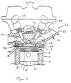
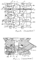
- Figures 1 is a partial cross-sectional view taken through a portion of a single cylinder of a conventional engine construction while Figure 2 is a lower plan view of the cylinder head and Figure 3 is a lower plan view of the cylinder head and Figure 3 is a cross-sectional view taken along the line 3-3 of Figure 2 and also along substantially the same plane as that of Figure 1.
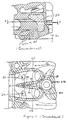
- Figure 4 is a further enlarged view of a portion of the cylinder head as shown in Figure 3 and Figure 5 is a cross-sectional view taken along the line 5-5 of Figure 4.
- an engine is indentified generally by the reference numeral 11 and is illustrated partially and in cross section taken through a single of the cylinders. It is believed that those skilled in the art will understand well how the conventional construction is employed to various types of multiple cylinder engines and, in the same sense, how the invention can be practiced with multiple cylinder engines of any configuration. Figure 1 may be considered to be a typical view for both the conventional construction and the embodiment of the invention which will be specifically described later.
- the engine 11 includes a cylinder block 12 which defines a cylinder bore 13 in which a piston 14 is supported for reciprocation.
- the piston 14 is connected by means of a connecting rod 15 to a crankshaft in a well known manner.
- a cylinder head assembly, indicated generally by the reference numeral 16 is affixed to the cylinder block 12 in a well known manner including by means of head bolts 17 which appear in certain of the figures.
- This cylinder head assembly 16 has a lower surface 18 that engages a cylinder head gasket 19 and closes the cylinder bore 13.
- a combustion chamber recess 21 is formed in alignment with the cylinder bore 13 and is surrounded by the gasket 19 and lower surface 18 for compression sealing.
- a pair of intake passages 22 are formed in the cylinder head assembly 16 on one side thereof and extend from a sealing surface 23 on the outer periphery of the cylinder head 16 and is adapted to be engaged by a suitable induction system including an intake manifold and charge formers (not shown) .
- These intake passages 22 terminate in valve seats formed in the cylinder head recess 21 and intake valves 24 are slidably supported in the cylinder head assembly 16 for the completion of the casting process.
- these openings also serve the purpose of providing water flow passages, as aforenoted.
- a flow passage 35 ( Figures 3 and 5) which extends in part through a dividing wall 36 that separates the non-siamese portion of the exhaust passages 36 from each other.
- This passage 35 communicates with a further discharge port 37 formed in the lower cylinder head surface 18. Coolant flows to the passage 35 from the area around spark plug walls 38 through passages 39.
- the water flow through the cylinder head cooling jacket 32 is as shown by the arrows in Figures 3 and 5.
- the passageway 35 and discharge port 37 are relatively small and a stagnant water area will be formed around the area between the exhaust passages 26. This can give rise to hot spots which will interfere with the effective cooling of the engine.
- This invention is adapted to be embodied in a cylinder head cooling arrangement for an overhead valve internal combustion engine comprising a cylinder head having a lower surface adapted to be sealingly engaged with a cylinder block around a cylinder bore.
- the cylinder head lower surface has a portion cooperating with the cylinder bore to form a combustion chamber.
- At least one valve seat is formed on one side of the cylinder head lower surface at one end of a first gas flow passage formed in the one side of the cylinder head.
- At least a pair of valve seats are formed on the other side of the cylinder head.
- At least a pair of valve seats are formed on the other side of the cylinder head lower surface portion at one end of respective second and third flow passages formed in the other side of the cylinder head.
- a water jacket is formed in the cylinder head at least in part around the flow passages.
- a coolant manifold section is disposed between said lower surface and said second and third flow passages and a coolant flow passage is formed in said cylinder head in an area between said second and third flow passages.
- the coolant manifold section communicates via at least on coolant discharge passageway to the coolant jacket of the cylinder block and the downstream end of the coolant flow passage opens into said coolant discharge passageway connecting the coolant jacket therewith.
- the water return passages that extend between the exhaust port 26 from the area between them are formed as substantially larger openings 51 which extend through the lower cylinder head surface 18.
- the cylinder head gasket 19, which does not appear in these figures, is made so as to obscure a substantial portion or preferably all of the openings 34 and thus substantially all of the water flow exiting the cylinder head must pass through the discharge opening 51.
- the discharge opening area of the total flow is approximately one-half of the inlet flow area so that velocity exiting the cylinder head will be substantially greater than that entering the cylinder head. This further ensures against any stagnant water being contained in the cylinder head and will ensure that there is adequate cooling of the cylinder head 16 and the ports therein.
Landscapes
- Engineering & Computer Science (AREA)
- Chemical & Material Sciences (AREA)
- Combustion & Propulsion (AREA)
- Mechanical Engineering (AREA)
- General Engineering & Computer Science (AREA)
- Cylinder Crankcases Of Internal Combustion Engines (AREA)
Applications Claiming Priority (2)
| Application Number | Priority Date | Filing Date | Title |
|---|---|---|---|
| JP35234792A JP3155993B2 (ja) | 1992-12-11 | 1992-12-11 | 多弁式エンジンのシリンダヘッド冷却構造 |
| JP352347/92 | 1992-12-11 |
Publications (2)
| Publication Number | Publication Date |
|---|---|
| EP0601612A1 true EP0601612A1 (fr) | 1994-06-15 |
| EP0601612B1 EP0601612B1 (fr) | 1997-03-12 |
Family
ID=18423440
Family Applications (1)
| Application Number | Title | Priority Date | Filing Date |
|---|---|---|---|
| EP93120079A Expired - Lifetime EP0601612B1 (fr) | 1992-12-11 | 1993-12-13 | Structure de refroidissement d'une culasse pour un moteur à multiples soupapes |
Country Status (4)
| Country | Link |
|---|---|
| US (1) | US5379729A (fr) |
| EP (1) | EP0601612B1 (fr) |
| JP (1) | JP3155993B2 (fr) |
| DE (1) | DE69308768T2 (fr) |
Cited By (2)
| Publication number | Priority date | Publication date | Assignee | Title |
|---|---|---|---|---|
| EP0924422A3 (fr) * | 1997-12-18 | 2000-02-23 | Nissan Motor Company, Limited | Moteur à combustion interne avec allumage par étincelle et injection directe |
| US8939115B2 (en) | 2009-11-18 | 2015-01-27 | Harley-Davidson Motor Company Group, LLC | Cylinder head cooling system |
Families Citing this family (20)
| Publication number | Priority date | Publication date | Assignee | Title |
|---|---|---|---|---|
| JP3601077B2 (ja) * | 1994-07-19 | 2004-12-15 | いすゞ自動車株式会社 | エンジンのシリンダヘッド |
| AT2334U1 (de) * | 1997-05-14 | 1998-08-25 | Avl List Gmbh | Mehrzylindrige brennkraftmaschine mit innerer gemischbildung |
| JPH116430A (ja) * | 1997-06-18 | 1999-01-12 | Yamaha Motor Co Ltd | 水冷多気筒エンジン |
| JP3883025B2 (ja) * | 1998-03-26 | 2007-02-21 | ヤマハマリン株式会社 | 筒内燃料噴射式エンジン |
| DE19943003C1 (de) | 1999-09-09 | 2000-11-09 | Porsche Ag | Zylinderkopf für eine wassergekühlte Brennkraftmaschine |
| DE19943001C1 (de) * | 1999-09-09 | 2000-10-26 | Porsche Ag | Zylinderkopf für eine wassergekühlte Brennkraftmaschine |
| JP4200379B2 (ja) * | 2004-10-12 | 2008-12-24 | 三菱自動車エンジニアリング株式会社 | エンジンの冷却水路構造 |
| JP4717586B2 (ja) * | 2005-10-24 | 2011-07-06 | 川崎重工業株式会社 | 燃料噴射式エンジン、及びこれを備える自動二輪車 |
| WO2007051212A2 (fr) * | 2005-11-04 | 2007-05-10 | Avl List Gmbh | Culasse |
| US7240644B1 (en) * | 2006-06-07 | 2007-07-10 | Ford Global Technologies, Llc | Internal combustion engine with cylinder head having directed cooling |
| AT506473B1 (de) * | 2009-04-23 | 2010-12-15 | Avl List Gmbh | Zylinderkopf einer brennkraftmaschine |
| US8931441B2 (en) * | 2012-03-14 | 2015-01-13 | Ford Global Technologies, Llc | Engine assembly |
| JP5729367B2 (ja) * | 2012-10-25 | 2015-06-03 | トヨタ自動車株式会社 | シリンダヘッドの冷却構造 |
| US9422886B2 (en) | 2013-07-03 | 2016-08-23 | Electro-Motive Diesel, Inc. | Cylinder head assembly having cooled valve insert |
| US20150007784A1 (en) * | 2013-07-03 | 2015-01-08 | Electro-Motive Diesel Inc. | Cylinder head having multiple cooling passages |
| GB2536030A (en) * | 2015-03-04 | 2016-09-07 | Gm Global Tech Operations Llc | A water jacket for an internal combustion engine |
| US9810134B2 (en) * | 2015-08-13 | 2017-11-07 | Ford Global Technologies, Llc | Internal combustion engine cooling system |
| SE541831C2 (en) | 2016-06-15 | 2019-12-27 | Scania Cv Ab | A Cylinder Head for an Internal Combustion Engine |
| AT521514B1 (de) * | 2018-09-14 | 2020-02-15 | Avl List Gmbh | Zylinderkopf |
| JP7442355B2 (ja) * | 2020-03-17 | 2024-03-04 | 本田技研工業株式会社 | 多気筒エンジンのシリンダヘッド |
Citations (4)
| Publication number | Priority date | Publication date | Assignee | Title |
|---|---|---|---|---|
| DE8621654U1 (de) * | 1986-08-12 | 1986-09-25 | Dr.Ing.H.C. F. Porsche Ag, 7000 Stuttgart | Zylinderkopf für eine flüssigkeitsgekühlte Brennkraftmaschine |
| DE3802886A1 (de) * | 1987-02-04 | 1988-08-18 | Avl Verbrennungskraft Messtech | Zylinderkopf fuer wassergekuehlte brennkraftmaschinen |
| EP0474216A1 (fr) * | 1990-09-04 | 1992-03-11 | Yamaha Hatsudoki Kabushiki Kaisha | Agencement de refroidissement d'une culasse pour un moteur à combustion interne à quatre temps |
| DE4116943C1 (en) * | 1991-05-24 | 1992-06-17 | Mercedes-Benz Aktiengesellschaft, 7000 Stuttgart, De | Liq. cooled IC engine four-valve cylinder head - whose bottom is thickened on outlet side down to outlet ducts |
Family Cites Families (3)
| Publication number | Priority date | Publication date | Assignee | Title |
|---|---|---|---|---|
| NL78718C (fr) * | 1950-09-09 | |||
| JPH0381548A (ja) * | 1989-08-23 | 1991-04-05 | Yamaha Motor Co Ltd | シリンダヘッドの液冷ジャケット構造 |
| JP2815066B2 (ja) * | 1989-12-11 | 1998-10-27 | ヤマハ発動機株式会社 | 4サイクルエンジンの冷却構造 |
-
1992
- 1992-12-11 JP JP35234792A patent/JP3155993B2/ja not_active Expired - Fee Related
-
1993
- 1993-12-13 EP EP93120079A patent/EP0601612B1/fr not_active Expired - Lifetime
- 1993-12-13 US US08/166,215 patent/US5379729A/en not_active Expired - Fee Related
- 1993-12-13 DE DE69308768T patent/DE69308768T2/de not_active Expired - Fee Related
Patent Citations (4)
| Publication number | Priority date | Publication date | Assignee | Title |
|---|---|---|---|---|
| DE8621654U1 (de) * | 1986-08-12 | 1986-09-25 | Dr.Ing.H.C. F. Porsche Ag, 7000 Stuttgart | Zylinderkopf für eine flüssigkeitsgekühlte Brennkraftmaschine |
| DE3802886A1 (de) * | 1987-02-04 | 1988-08-18 | Avl Verbrennungskraft Messtech | Zylinderkopf fuer wassergekuehlte brennkraftmaschinen |
| EP0474216A1 (fr) * | 1990-09-04 | 1992-03-11 | Yamaha Hatsudoki Kabushiki Kaisha | Agencement de refroidissement d'une culasse pour un moteur à combustion interne à quatre temps |
| DE4116943C1 (en) * | 1991-05-24 | 1992-06-17 | Mercedes-Benz Aktiengesellschaft, 7000 Stuttgart, De | Liq. cooled IC engine four-valve cylinder head - whose bottom is thickened on outlet side down to outlet ducts |
Cited By (3)
| Publication number | Priority date | Publication date | Assignee | Title |
|---|---|---|---|---|
| EP0924422A3 (fr) * | 1997-12-18 | 2000-02-23 | Nissan Motor Company, Limited | Moteur à combustion interne avec allumage par étincelle et injection directe |
| US6196185B1 (en) | 1997-12-18 | 2001-03-06 | Nissan Motor Co., Ltd. | Fuel direct injection spark ignition type internal combustion engine |
| US8939115B2 (en) | 2009-11-18 | 2015-01-27 | Harley-Davidson Motor Company Group, LLC | Cylinder head cooling system |
Also Published As
| Publication number | Publication date |
|---|---|
| JP3155993B2 (ja) | 2001-04-16 |
| DE69308768D1 (de) | 1997-04-17 |
| DE69308768T2 (de) | 1997-06-26 |
| US5379729A (en) | 1995-01-10 |
| JPH06173677A (ja) | 1994-06-21 |
| EP0601612B1 (fr) | 1997-03-12 |
Similar Documents
| Publication | Publication Date | Title |
|---|---|---|
| EP0601612A1 (fr) | Structure de refroidissement d'une culasse pour un moteur à multiples soupapes | |
| US3818878A (en) | Improved cylinder head cooling | |
| US6681727B2 (en) | Cylinder head for a plurality of cylinders | |
| US5890461A (en) | Engine cylinder head cooling arrangement | |
| US4730579A (en) | Internal combustion engine cylinder head with port coolant passage independent of and substantially wider than combustion chamber coolant passage | |
| US6202603B1 (en) | Internal combustion engine | |
| USRE37289E1 (en) | Induction system for engine | |
| US5630386A (en) | Intake structure for V-type engine | |
| EP1251260B1 (fr) | Moteur a combustion interne | |
| EP0500123A1 (fr) | Système d'aspiration d'un moteur à combustion interne | |
| US4971008A (en) | Porting arrangement for multi-valve engine | |
| GB2290111A (en) | Internal combustion engine cylinder head cooling | |
| EP0365148A3 (fr) | Culasse à courant tangentiel | |
| JPS6213759A (ja) | 内燃機関のシリンダヘツドの冷却水通路構造 | |
| US5222464A (en) | Four cycle engine | |
| JP3618593B2 (ja) | 内燃機関におけるシリンダヘッドの構造 | |
| CA1273253A (fr) | Culasse de moteur a conduits de caloporteur avoisiant les chambres de combustion et ayant une surface en coupe generalement uniforme | |
| JPH09195788A (ja) | 内燃エンジン | |
| US4520627A (en) | Turbocharged internal combustion engine | |
| US6155228A (en) | Multicylinder four-stroke internal combustion engine | |
| JPH04350348A (ja) | 水冷式多気筒エンジンの冷却構造 | |
| JPH0566219U (ja) | エンジンにおけるシリンダブロックの冷却装置 | |
| JPH06330812A (ja) | 内燃機関のシリンダヘッド | |
| AU607465B2 (en) | Improvements relating to multi-cylindered two stroke cycle engines | |
| JPH05223004A (ja) | エンジンのエンジンブロック |
Legal Events
| Date | Code | Title | Description |
|---|---|---|---|
| PUAI | Public reference made under article 153(3) epc to a published international application that has entered the european phase |
Free format text: ORIGINAL CODE: 0009012 |
|
| AK | Designated contracting states |
Kind code of ref document: A1 Designated state(s): DE FR GB |
|
| 17P | Request for examination filed |
Effective date: 19941214 |
|
| 17Q | First examination report despatched |
Effective date: 19950808 |
|
| GRAG | Despatch of communication of intention to grant |
Free format text: ORIGINAL CODE: EPIDOS AGRA |
|
| GRAH | Despatch of communication of intention to grant a patent |
Free format text: ORIGINAL CODE: EPIDOS IGRA |
|
| GRAH | Despatch of communication of intention to grant a patent |
Free format text: ORIGINAL CODE: EPIDOS IGRA |
|
| GRAA | (expected) grant |
Free format text: ORIGINAL CODE: 0009210 |
|
| AK | Designated contracting states |
Kind code of ref document: B1 Designated state(s): DE FR GB |
|
| REF | Corresponds to: |
Ref document number: 69308768 Country of ref document: DE Date of ref document: 19970417 |
|
| ET | Fr: translation filed | ||
| PLBE | No opposition filed within time limit |
Free format text: ORIGINAL CODE: 0009261 |
|
| STAA | Information on the status of an ep patent application or granted ep patent |
Free format text: STATUS: NO OPPOSITION FILED WITHIN TIME LIMIT |
|
| 26N | No opposition filed | ||
| REG | Reference to a national code |
Ref country code: GB Ref legal event code: IF02 |
|
| PGFP | Annual fee paid to national office [announced via postgrant information from national office to epo] |
Ref country code: FR Payment date: 20021210 Year of fee payment: 10 |
|
| PG25 | Lapsed in a contracting state [announced via postgrant information from national office to epo] |
Ref country code: FR Free format text: LAPSE BECAUSE OF NON-PAYMENT OF DUE FEES Effective date: 20040831 |
|
| REG | Reference to a national code |
Ref country code: FR Ref legal event code: ST |
|
| PGFP | Annual fee paid to national office [announced via postgrant information from national office to epo] |
Ref country code: DE Payment date: 20061207 Year of fee payment: 14 |
|
| PGFP | Annual fee paid to national office [announced via postgrant information from national office to epo] |
Ref country code: GB Payment date: 20061213 Year of fee payment: 14 |
|
| GBPC | Gb: european patent ceased through non-payment of renewal fee |
Effective date: 20071213 |
|
| PG25 | Lapsed in a contracting state [announced via postgrant information from national office to epo] |
Ref country code: DE Free format text: LAPSE BECAUSE OF NON-PAYMENT OF DUE FEES Effective date: 20080701 |
|
| PG25 | Lapsed in a contracting state [announced via postgrant information from national office to epo] |
Ref country code: GB Free format text: LAPSE BECAUSE OF NON-PAYMENT OF DUE FEES Effective date: 20071213 |