EP0601669A1 - Dispositif pour le déplacement des navires d'un cours d'eau à l'autre - Google Patents
Dispositif pour le déplacement des navires d'un cours d'eau à l'autre Download PDFInfo
- Publication number
- EP0601669A1 EP0601669A1 EP93203447A EP93203447A EP0601669A1 EP 0601669 A1 EP0601669 A1 EP 0601669A1 EP 93203447 A EP93203447 A EP 93203447A EP 93203447 A EP93203447 A EP 93203447A EP 0601669 A1 EP0601669 A1 EP 0601669A1
- Authority
- EP
- European Patent Office
- Prior art keywords
- water tank
- guideways
- water
- suspension
- aid
- Prior art date
- Legal status (The legal status is an assumption and is not a legal conclusion. Google has not performed a legal analysis and makes no representation as to the accuracy of the status listed.)
- Granted
Links
Images

Classifications
-
- E—FIXED CONSTRUCTIONS
- E02—HYDRAULIC ENGINEERING; FOUNDATIONS; SOIL SHIFTING
- E02C—SHIP-LIFTING DEVICES OR MECHANISMS
- E02C3/00—Inclined-plane ship-lifting mechanisms ; Systems for conveying barges or lighters over land, e.g. by railway
Definitions
- the invention relates to a device for moving ships from one waterway to another waterway using a water tank, the water tank moving horizontally and vertically.
- Such devices also called boat lifts, are used, among other things, in hilly areas, the water tank being transported on rollers from one waterway via a flat inclined path to the higher or lower waterway.
- the ship is transported in the water tank in the transverse direction or in the longitudinal direction. Examples of these can be seen in the Rhine-Marne Canal, in Saverne (France) and in the Canal from Brussels to Charleroi, in Ronquiées (Belgium).
- Such devices or ship hoists have the purpose of transferring ships from one waterway to another, with a large gradient between the waterways, without having to use a series of (expensive) chamber locks.
- the body of water in which the ship is located is, in its entirety, moved to another level.
- the object of the invention is to provide a device of the type mentioned in the preamble, the floor surface or the subsurface between the waterways not needing to be transformed into a flat inclined path.
- the device has guideways for moving the water tank always free from and above the surface of the floor between the waterways.
- the floor need not be provided with a flat inclined track.
- the guideways preferably extend to above or into the guideways. This will lift the water tank over a quay or dike that may be present.
- the guideways advantageously have an envelope for the vertical movement of the water tank, the movement going from top to bottom, and they are preferably horizontal over part of their length.
- the water tank has cantilevered axes that the water tank wear.
- the water tank can be moved between the guideways and are located directly next to the guideways, so that the construction height is kept limited while maintaining the advantages of the construction according to the invention.
- the water container is advantageously suspended between suspension means, which are displaced by means of drive means over the guideways, and which support the projecting axes.
- the water container is preferably suspended between two suspension means with the aid of a hinge cantilever axis for each suspension element, the hinge cantilever axes being located above the center of gravity of the water container, and wherein electronically speed-controlled drive means for controlling the displacement of the water container depending on the inertia of the water container and its contents are arranged to control acceleration and deceleration effects and to stabilize the water tank.
- electronically speed-controlled drive means for controlling the displacement of the water container depending on the inertia of the water container and its contents are arranged to control acceleration and deceleration effects and to stabilize the water tank.
- electronically speed-controlled drive means can be controlled in such a way that the water tank remains stable. It is about mastering the fluctuation and possibly receding it. The various movements must not reinforce each other.
- the suspensions are advantageously stabilized by one or more stabilizing means, preferably one or more hydraulic cylinders.
- a stabilizing means is advantageously arranged on each longitudinal side of the water tank on both sides of the joint suspension.
- the device is provided with detection means, namely a displacement meter on the hydraulic cylinders and water level meters such as capacitive rods or pressure meters along the walls in the water tank, and preferably an inclinometer on the water tank, a pressure meter in the hydraulic cylinders and / or an accelerometer in the pivot point of a cantilevered axis and in the bottom of the water tank below the pivot point, and a processing and control unit which controls the drive means and the hydraulic cylinders with the aid of data from the detection means.
- the level of the water tank is determined on the basis of the data from the dislocation meter; the state of the suspension means is known from the position thereof on the guideways.
- the preferably present inclinometer on the water tank measures its inclination directly.
- Pressure gauges in hydraulic cylinders indicate a possible overload of what the drive means can be controlled to relieve the cylinders.
- the accelerometers provide information about the water container remaining or the water container running ahead on the suspension means.
- the drive means and the hydraulic cylinders can then be controlled in order to stabilize the water tank.
- the water tank hangs between four or more suspension means with the aid of an articulated suspension, the suspension being adjustable in height, and preferably being hydraulic jacks.
- the device in this alternative device is also provided with detection means, namely a displacement meter for each suspension and water level meters such as capacitive rods or pressure meters along the walls in the water tank, and preferably an inclinometer on Water tank and / or an accelerometer in the pivot point of a cantilevered axis and in the bottom of the water tank, and a processing and control unit which controls data using the data from the detection means electronically controlled drive means and the adjustable suspensions.
- detection means namely a displacement meter for each suspension and water level meters such as capacitive rods or pressure meters along the walls in the water tank, and preferably an inclinometer on Water tank and / or an accelerometer in the pivot point of a cantilevered axis and in the bottom of the water tank
- a processing and control unit which controls data using the data from the detection means electronically controlled drive means and the adjustable suspensions.
- the stabilization is carried out analogously to that of the device with two suspension means.
- suspension means are wheeled trolleys, so that the trolleys drive onto the guideways by driving the wheels over rails.
- the guideways are provided with pin tracks on steep parts and / or on vertical end parts, on which pinions belonging to the driven trolleys engage.
- the driving of the pinion then represents the displacement of the water tank for sure.
- the driven trucks preferably have means for bringing the pinions into a position placed on the pin tracks. These means can consist of one-way clutches that are fixed in the pin tracks if the pinion is correct.
- the guideways are provided with a bottom to form a trough, with a compressor under the water tank generating an airfoil or water, or alternatively, between the water tank and an electromagnetic airfoil is created at the bottom of the trough.
- the device can be dismantled for temporary use, for example between a wet dig and a river.
- the guideways can be rotated about a vertical axis in a horizontal surface. This makes it possible to connect the boat lift alternately on two or more routes at one end of the boat lift. It is also possible for part of the guideways to be rotatable in a horizontal surface for connection to other guideways.
- the device In busy shipping traffic or at greater distances, it is advantageous if the device has three or more guideways, one or more water tanks being displaceable on both sides of the inner path or lanes, so that there are no long waiting times.
- the device can be operated at least in part by hand, as it happens, depending on the scope, in a chamber lock. It is also possible to operate the device fully automatically.
- the approaching ships are then detected with sensors, after which folding gates open.
- the ships can enter via navigation signals, after which the flaps close, the lorries begin to move and stop on the opposite side. Then the flaps open and the shipping signals guide the ships out of the water tank.
- the device has electronically controlled actuating means.
- the device can also be operated remotely.
- a system can be arranged in order to be able to operate the ship lift if the sensors malfunction.
- the device has remotely controllable, electronically controlled operating means such as camera systems, an operating center elsewhere, such as an operating center for bridges, controlling the device.
- Fig. 1 is an overview of a device according to the invention, which connects two routes, with a schematic representation of a wagon and a water tank.
- FIG. 2 shows a lore and the water tank from FIG. 1 on average along line II-II in FIG. 3.
- Fig. 3 shows water tank, wagon and guideway on average along line III-III in Fig. 2nd
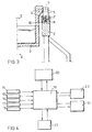
- Fig. 4 shows a control scheme for controlling the water tank in the previous figures.
- Fig. 1 the ship's hoist 1 is shown, which has a water tank 3 and two trucks 5, moving over the guideways 2, one of which can be seen. It can be clearly seen that the water tank from the floor surface remains free, so that the profile of the free space of railways and highways is not cut.
- the water tank 3 has two folding gates 4.
- the lore 5 is connected to the water tank by means of an articulated suspension 6.
- Hydraulic cylinders 11 stabilize the water tank, the water and the ships against rolling.
- the wagon 5 has wheels 7 which run over the guideway 2.
- Fig. 3 shows that the wheels 7 run on rails 8.
- the wheels are driven by a drive in the wagon 5.
- a pin path 10 is arranged on the guideways, in which driven pinions 9 engage in the wagon.
- the driving of the pinion 9 then ensures the displacement of the water tank, in that the wheels 7 can no longer slide over the rail 8.
- the lore 5 has means for bringing the pinion 9 into a position which is set down on the associated pin path.
- one-way clutches can be used, which are fixed in the pin path when the pinions engage correctly.
- the ship's hoist is equipped with speed-controlled drive means (not shown) for controlling the displacement of the water tank.
- These drive means can be of any suitable type and can be, for example, motors.
- the course becomes from calculations of the acceleration and deceleration effects depending on the inertia of the water tank and its contents the speed of the water tank derived, the water tank remains stable. This data is stored in a programmed computer, by means of which the drive means are controlled.
- Fig. 2 shows that for this purpose detection means are arranged on the water tank and its suspension.
- An accelerometer 14 is arranged in the pivot point of the suspension 6 and in the base of the water tank, an inclinometer 16 is arranged on the water tank, a pressure meter 17 is arranged in the hydraulic cylinders 11 and a displacement meter 18 is arranged on the hydraulic cylinders 11.
- a water level meter 15 is placed in the water tank at intervals of 10 meters.
- This water level meter can be, for example, a capacitive rod, a pressure meter or a bubble tube, in the case of which the water height can be determined from the pressure to form air bubbles which are pressed in the bubble tubes. It will not always be necessary to apply all of these detection means; the water level meter 15 with a displacement meter 18 or an inclinometer 16 may be sufficient.
- a computer processes the data and primarily controls the hydraulic cylinders, and secondly controls the drive means to avoid lurching and releasing water.
- Fig. 4 shows a control diagram for the ship lift.
- Detection means 14, 15, 16, 17, 18 deliver data to a central computer 19.
- the computer controls the hydraulic cylinders or hydraulic jacks 21.
- the computer also controls the speed-controlled drive means 22.
- the computer is connected to a communication center 23, so that an operator can follow the activities of the ship lift and possibly intervene.
- the boat lift 1 is designed for an area with a small gradient, for example, where a lake and a river are approximately 200 meters apart. In the past, an "overtoom" was used at this point, with the ships being pulled out of the water using tree trunks over a flattened embankment.
- the device operates as follows.
- the water tank 3 is driven into a driveway, in which there is a ship that transports to the other driveway would be.
- a folding gate 4 is opened, the ship goes into the water tank 3; the folding gate 4 is closed.
- the drives in the two lorries move the water tank 3 by ship via the guideways to the other route, the water tank being transported from one route, free of the subsurface or from the surface of the ground, possibly first vertically, then horizontally or at an incline to the other route .
- the other folding gate 4 is opened and the ship moves out of the water tank 3.
- the ship has been lifted over the dike body as it were.
- the operation of the ship lift 1 with hydraulic cylinders 11 or with adjustable suspensions can take place automatically with the aid of electronically controlled operating means. It is also possible to operate the boat lift remotely with the help of remote-controlled, semi or fully automatic electronically controlled controls.
Landscapes
- Engineering & Computer Science (AREA)
- Ocean & Marine Engineering (AREA)
- Mechanical Engineering (AREA)
- Civil Engineering (AREA)
- General Engineering & Computer Science (AREA)
- Structural Engineering (AREA)
- Placing Or Removing Of Piles Or Sheet Piles, Or Accessories Thereof (AREA)
- Underground Or Underwater Handling Of Building Materials (AREA)
- Other Liquid Machine Or Engine Such As Wave Power Use (AREA)
Applications Claiming Priority (2)
| Application Number | Priority Date | Filing Date | Title |
|---|---|---|---|
| NL9202123A NL9202123A (nl) | 1992-12-08 | 1992-12-08 | Inrichting voor het verplaatsen van schepen van een vaarweg naar een andere vaarweg. |
| NL9202123 | 1992-12-08 |
Publications (2)
| Publication Number | Publication Date |
|---|---|
| EP0601669A1 true EP0601669A1 (fr) | 1994-06-15 |
| EP0601669B1 EP0601669B1 (fr) | 1997-02-26 |
Family
ID=19861605
Family Applications (1)
| Application Number | Title | Priority Date | Filing Date |
|---|---|---|---|
| EP19930203447 Expired - Lifetime EP0601669B1 (fr) | 1992-12-08 | 1993-12-07 | Dispositif pour le déplacement des navires d'un cours d'eau à l'autre |
Country Status (3)
| Country | Link |
|---|---|
| EP (1) | EP0601669B1 (fr) |
| DE (1) | DE59305535D1 (fr) |
| NL (1) | NL9202123A (fr) |
Cited By (3)
| Publication number | Priority date | Publication date | Assignee | Title |
|---|---|---|---|---|
| WO2001023673A1 (fr) * | 1999-09-28 | 2001-04-05 | Ricardo Teixeira Mendes | Systeme et procede pour transporter des embarcations autour de barrieres de navigation disposees sur un plan d'eau |
| GB2425558A (en) * | 2005-04-29 | 2006-11-01 | Alec George Dodd | Pivoted arm system for transporting canal boats across fixed obstacles |
| FR2961463A1 (fr) * | 2010-06-21 | 2011-12-23 | Ex O Mediterranee | Systeme transbordeur de charge pour le franchissement d'ouvrage |
Citations (7)
| Publication number | Priority date | Publication date | Assignee | Title |
|---|---|---|---|---|
| DE179391C (fr) * | ||||
| DE258877C (fr) * | ||||
| DE143656C (fr) * | ||||
| FR512214A (fr) * | 1914-05-16 | 1921-01-18 | Robert B Goldschmidt | Système de locomotion amphibie permettant aux engins de transport fluviaux de franchir les rapides ou passes dangereuses et d'éviter les courbes du fleuve sans travaux d'art couteux |
| US1994696A (en) * | 1933-03-11 | 1935-03-19 | Maschf Augsburg Nuernberg Ag | Device for hauling up ships, etc. |
| DE2738904A1 (de) * | 1976-08-31 | 1978-03-02 | Nissan Motor | Fahrzeug fuer hochbahn |
| SU1118741A1 (ru) * | 1982-12-07 | 1984-10-15 | Ленинградский Институт Водного Транспорта | Устройство автоматического управлени судоходным однокамерным шлюзом |
-
1992
- 1992-12-08 NL NL9202123A patent/NL9202123A/nl not_active Application Discontinuation
-
1993
- 1993-12-07 EP EP19930203447 patent/EP0601669B1/fr not_active Expired - Lifetime
- 1993-12-07 DE DE59305535T patent/DE59305535D1/de not_active Expired - Fee Related
Patent Citations (7)
| Publication number | Priority date | Publication date | Assignee | Title |
|---|---|---|---|---|
| DE179391C (fr) * | ||||
| DE258877C (fr) * | ||||
| DE143656C (fr) * | ||||
| FR512214A (fr) * | 1914-05-16 | 1921-01-18 | Robert B Goldschmidt | Système de locomotion amphibie permettant aux engins de transport fluviaux de franchir les rapides ou passes dangereuses et d'éviter les courbes du fleuve sans travaux d'art couteux |
| US1994696A (en) * | 1933-03-11 | 1935-03-19 | Maschf Augsburg Nuernberg Ag | Device for hauling up ships, etc. |
| DE2738904A1 (de) * | 1976-08-31 | 1978-03-02 | Nissan Motor | Fahrzeug fuer hochbahn |
| SU1118741A1 (ru) * | 1982-12-07 | 1984-10-15 | Ленинградский Институт Водного Транспорта | Устройство автоматического управлени судоходным однокамерным шлюзом |
Non-Patent Citations (2)
| Title |
|---|
| DATABASE WPI Section EI Week 8519, Derwent World Patents Index; Class W06, AN 85-114732 * |
| DATABASE WPI Week 7810, Derwent World Patents Index; AN 78-C0136A * |
Cited By (4)
| Publication number | Priority date | Publication date | Assignee | Title |
|---|---|---|---|---|
| WO2001023673A1 (fr) * | 1999-09-28 | 2001-04-05 | Ricardo Teixeira Mendes | Systeme et procede pour transporter des embarcations autour de barrieres de navigation disposees sur un plan d'eau |
| GB2425558A (en) * | 2005-04-29 | 2006-11-01 | Alec George Dodd | Pivoted arm system for transporting canal boats across fixed obstacles |
| GB2425558B (en) * | 2005-04-29 | 2010-05-05 | Alec George Dodd | Apparatus for transporting canal boats across fixed obstacles |
| FR2961463A1 (fr) * | 2010-06-21 | 2011-12-23 | Ex O Mediterranee | Systeme transbordeur de charge pour le franchissement d'ouvrage |
Also Published As
| Publication number | Publication date |
|---|---|
| EP0601669B1 (fr) | 1997-02-26 |
| NL9202123A (nl) | 1994-07-01 |
| DE59305535D1 (de) | 1997-04-03 |
Similar Documents
| Publication | Publication Date | Title |
|---|---|---|
| DE1556636A1 (de) | Container-Umschlaganlage | |
| DE10353455B4 (de) | Schienengeführtes Transportsystem für Container | |
| CH703859B1 (de) | Umschlagvorrichtung für einen Horizontal-Umschlag bei einem Container-Transportsystem | |
| EP1190947A1 (fr) | Véhicule pour la manoeuvre des avions | |
| DE69623989T2 (de) | Eisenbahngüterwagen | |
| DE2301797A1 (de) | Verfahren und einrichtungen zum transport und positionieren vorgefertigter baugruppen beim bau von seeschiffen | |
| DE60130303T2 (de) | Vorichtung zum Lagern von Booten mit automatischem an Land und ins Wasser setzen | |
| EP0601669B1 (fr) | Dispositif pour le déplacement des navires d'un cours d'eau à l'autre | |
| DE2555316A1 (de) | Be- und entladeeinrichtungen fuer container von schiffen | |
| EP3571354B1 (fr) | Dispositif de pose de pont destiné à poser un pont en particulier d'une seule pièce | |
| EP1845005A2 (fr) | Véhicule sur rails et transport ferroviaire | |
| DE3421418A1 (de) | Umschlagzentren fuer behaelter | |
| DE4427468A1 (de) | Eine aus zwei Kränen bestehende Krananlage, die auf ein Straßen-, Schienen- oder Binnenwasserfahrzeug aufgebaut ist und die für das Fördern von Containern und Wechselbehältern geeignet ist | |
| DE4102795C2 (de) | Betontransportwagen einer Schienenhängebahn | |
| DE2947030C2 (de) | Fahrzeug zum Slippen eines Bootes | |
| DE3837726A1 (de) | Verfahren zur verladung von schwergut mit einer schwergut-verladebruecke mit mehr als einer hebe- und senkvorrichtung | |
| DE69631371T2 (de) | Führungsschacht für Container-Kräne | |
| DE19713489A1 (de) | Verladebrücke und Verfahren zum Umschlagen von Gütern, insbesondere an Schiffsanliegeplätzen | |
| EP0990557B1 (fr) | Dispositif de transport pour charges lourdes dans le transport du type ro-ro et procédé pour utiliser le dispositif de transport | |
| DE4124969A1 (de) | Nutzfahrzeug fuer ein transportsystem mit containern, insbesondere cargo 2000-behaeltern | |
| CH507418A (de) | Anlage zum Zentrieren eines strassengängigen Fahrzeuges beim Einfahren in einen Raum | |
| DE1919037A1 (de) | Foerdervorrichtung fuer Leichter und Lukendeckel an Bord eines Schiffes | |
| DE3249387T1 (de) | Maschine zum Handhaben von Rohren | |
| DE202004001241U1 (de) | Rohr- oder Stangenlager für eine Bohranlage | |
| DE2721947A1 (de) | Spreader fuer die verladung von containern |
Legal Events
| Date | Code | Title | Description |
|---|---|---|---|
| PUAI | Public reference made under article 153(3) epc to a published international application that has entered the european phase |
Free format text: ORIGINAL CODE: 0009012 |
|
| AK | Designated contracting states |
Kind code of ref document: A1 Designated state(s): BE DE FR NL |
|
| 17P | Request for examination filed |
Effective date: 19941205 |
|
| 17Q | First examination report despatched |
Effective date: 19950803 |
|
| GRAG | Despatch of communication of intention to grant |
Free format text: ORIGINAL CODE: EPIDOS AGRA |
|
| GRAH | Despatch of communication of intention to grant a patent |
Free format text: ORIGINAL CODE: EPIDOS IGRA |
|
| GRAH | Despatch of communication of intention to grant a patent |
Free format text: ORIGINAL CODE: EPIDOS IGRA |
|
| GRAA | (expected) grant |
Free format text: ORIGINAL CODE: 0009210 |
|
| AK | Designated contracting states |
Kind code of ref document: B1 Designated state(s): BE DE FR NL |
|
| REF | Corresponds to: |
Ref document number: 59305535 Country of ref document: DE Date of ref document: 19970403 |
|
| ET | Fr: translation filed | ||
| PLBE | No opposition filed within time limit |
Free format text: ORIGINAL CODE: 0009261 |
|
| 26N | No opposition filed | ||
| PGFP | Annual fee paid to national office [announced via postgrant information from national office to epo] |
Ref country code: FR Payment date: 20021224 Year of fee payment: 10 |
|
| PGFP | Annual fee paid to national office [announced via postgrant information from national office to epo] |
Ref country code: BE Payment date: 20030107 Year of fee payment: 10 |
|
| PGFP | Annual fee paid to national office [announced via postgrant information from national office to epo] |
Ref country code: DE Payment date: 20030217 Year of fee payment: 10 |
|
| PG25 | Lapsed in a contracting state [announced via postgrant information from national office to epo] |
Ref country code: BE Free format text: LAPSE BECAUSE OF NON-PAYMENT OF DUE FEES Effective date: 20031231 |
|
| PGFP | Annual fee paid to national office [announced via postgrant information from national office to epo] |
Ref country code: NL Payment date: 20031231 Year of fee payment: 11 |
|
| BERE | Be: lapsed |
Owner name: *VAN DRIEL MECHATRONICA B.V. Effective date: 20031231 |
|
| PG25 | Lapsed in a contracting state [announced via postgrant information from national office to epo] |
Ref country code: DE Free format text: LAPSE BECAUSE OF NON-PAYMENT OF DUE FEES Effective date: 20040701 |
|
| PG25 | Lapsed in a contracting state [announced via postgrant information from national office to epo] |
Ref country code: FR Free format text: LAPSE BECAUSE OF NON-PAYMENT OF DUE FEES Effective date: 20040831 |
|
| REG | Reference to a national code |
Ref country code: FR Ref legal event code: ST |
|
| PG25 | Lapsed in a contracting state [announced via postgrant information from national office to epo] |
Ref country code: NL Free format text: LAPSE BECAUSE OF NON-PAYMENT OF DUE FEES Effective date: 20050701 |
|
| NLV4 | Nl: lapsed or anulled due to non-payment of the annual fee |
Effective date: 20050701 |