EP0601685A2 - Getriebesystem und Druckbandkassette hiermit - Google Patents
Getriebesystem und Druckbandkassette hiermit Download PDFInfo
- Publication number
- EP0601685A2 EP0601685A2 EP93303279A EP93303279A EP0601685A2 EP 0601685 A2 EP0601685 A2 EP 0601685A2 EP 93303279 A EP93303279 A EP 93303279A EP 93303279 A EP93303279 A EP 93303279A EP 0601685 A2 EP0601685 A2 EP 0601685A2
- Authority
- EP
- European Patent Office
- Prior art keywords
- gear
- gear system
- ribbon
- gears
- teeth
- Prior art date
- Legal status (The legal status is an assumption and is not a legal conclusion. Google has not performed a legal analysis and makes no representation as to the accuracy of the status listed.)
- Withdrawn
Links
Images


Classifications
-
- B—PERFORMING OPERATIONS; TRANSPORTING
- B41—PRINTING; LINING MACHINES; TYPEWRITERS; STAMPS
- B41J—TYPEWRITERS; SELECTIVE PRINTING MECHANISMS, i.e. MECHANISMS PRINTING OTHERWISE THAN FROM A FORME; CORRECTION OF TYPOGRAPHICAL ERRORS
- B41J33/00—Apparatus or arrangements for feeding ink ribbons or like character-size impression-transfer material
- B41J33/14—Ribbon-feed devices or mechanisms
- B41J33/24—Ribbon-feed devices or mechanisms with drive applied directly to ribbon
- B41J33/28—Ribbon-feed devices or mechanisms with drive applied directly to ribbon by mechanism pulling or gripping the ribbon
Definitions
- the invention relates to a gear system and a printing ribbon cartridge including the gear system.
- ribbon cartridges for impact printing use a gear drive system to continuously feed ribbon through the printing device in which the cartridge is installed.
- a drive gear in the cartridge is positioned to engage a drive mechanism on the printer, which rotates continuously, or as each character is printed, depending on printer design. This rotation causes the drive gear and an associated intermeshing idler gear to rotate, which pulls the ribbon through the cartridge.
- the ribbon is usually formed as a continuous loop, the bulk of which is stored in a fan folded or random arrangement known as a "fabric pack" in a ribbon chamber within the cartridge. From the ribbon chamber, the ribbon feeds through a ribbon outlet, past a print head, and through a ribbon inlet to return to the ribbon chamber.
- the gear drive system In order to feed ribbon through the cartridge, the gear drive system must pull the ribbon from the ribbon outlet, draw it into the ribbon inlet, and discharge it into the ribbon chamber. This operation should require only minimal mechanical torque in order to reduce ribbon web tension and avoid imposing excessive power or mechanical demands on the printing device.
- the drive gear system must be capable of accommodating momentary increases in ribbon tension caused when the ribbon fabric becomes partially trapped within the ribbon chamber. This often results from a "buried loop", which is caused when one partial loop of the ribbon fabric is trapped between the side wall of the cartridge and the fabric pack or within the pack itself. Excessive ribbon tension resulting from a buried loop can cause the ribbon to slip between the gears. Such "stalling" can cause either light and dark print or even cartridge or printer failure.
- Prior art ribbon cartridges commonly use either a fixed gear drive system or a spring loaded gear system.
- a fixed gear system a pair of spur gears frequently having deep, large teeth are used to pull the ribbon.
- One of the gears is the drive gear and the other gear is an intermeshing idler gear. Both are mounted on fixed rotational axes, typically holes in the top and bottom of the cartridge.
- a disadvantage of fixed gear systems is that the spacing between the gear axes cannot be precisely controlled due to manufacturing tolerances inherent in molded plastic components. This can cause wide swings in performance between the extremes of binding with high torque (causing possible machine damage or stalling) and fabric slippage resulting in light/dark print.
- a spring loaded gear system In a spring loaded gear system the drive gear is rotatably mounted in a fixed axis while an intermeshing idler gear is slidably mounted to allow lateral displacement of the idler gear rotational axis toward the drive gear axis. Uniform drive torque is maintained by resiliently biasing the idler gear toward the drive gear using a spring loading system.
- a disadvantage of the spring loaded gear system is that more parts are required, which increases the cost of labour and materials, and adds more tolerances for potential variances.
- a higher drive torque is generated by the spring force required to maintain desired traction on the ribbon fabric.
- Spring loaded gear systems also allow backward rotation of the gears unless an additional ratchet is utilized to allow one-way rotation only. Reverse manual rotation frequently results in jams or failure of the system.
- a gear system including two gears between which a flexible element passes in use, the two gears including undercut teeth which intermesh.
- the intermeshing of the undercut teeth ensures a greater frictional grip on the flexible element and the flexible element may be pinched between undercut surfaces of the teeth so that the pulling force, if the gear system is driven, is increased and the likelihood of slipback through the system is decreased.
- the undercut side contact surfaces of the teeth are preferably smoothly curved and may be concave.
- the end surfaces of the teeth may be smoothly curved and in one embodiment may be convex.
- the floor of the tooth receiving gap between teeth is smoothly curved and may be concave.
- the teeth are preferably smoothly curved. This prevents harm to the ribbon while ensuring that there are large surfaces for frictional contact.
- a gear system including two intermeshed gears between which a flexible element passes in use, each gear including alternating teeth and tooth receiving gaps, and the end surface of each tooth and the floor of each tooth receiving gap being so shaped as to define at least one void therebetween when the tooth and gap floor are at their closest.
- the void or additional spacing ensures that there are a plurality of frictional contact points rather than a single long surface.
- each gear tooth includes at least one recess to define said at least one void.
- the or each recess may be a groove across the gear teeth. This may be particularly useful where the gear system is for a print ribbon as the grooves ensure that squeezing of the ribbon does not reduce the ink content.
- a gear system including two intermeshed gears between which a flexible element passes in use in a forwards direction, at least one of the gears being retained such that it is movable in the forwards direction or at an acute angle thereto into a position closer to the other gear.
- gears may be idler gears. In that case, then tension on the flexible element will cause relative movement of the gears together.
- one or both gears may be a drive gear. In this case if the element is slowed downstream of the gear system, the gears will be moved together so that the pulling force on the flexible element is increased.
- the gears comprise a fixed drive gear and a movable idler gear.
- the or each movable gear may include an axle slidable along a slide surface to enable the or each movable gear to move towards the or each other gear.
- the or each slide surface may form one surface of a slot retaining the axle and thereby the gear.
- the flexible element is preferably a ribbon and may be a printing ribbon.
- a printing ribbon cartridge including a gear system according to any previous aspect of the invention.
- This aspect of the invention is concerned with an improved ribbon cartridge having an endless printing ribbon and a ribbon inlet and outlet through which a portion of the printing ribbon is fed outside the cartridge for use by a printing device in a printing operation.
- the ribbon cartridge includes a low torque, high traction ribbon drive system.
- the ribbon drive system includes a gear system formed by a drive gear and one or more idler gears arranged in intermeshing engagement. Each of the gears may have a compound curvilinear tooth configuration including one or more ribbon engagement ribs to provide enhanced ribbon pulling traction and reduced drive torque.
- At least one of the gears may be slidably mounted in the ribbon cartridge and positioned in the ribbon path so as to be driven toward an adjacent intermeshing gear by the ribbon itself or rotationally pulled together.
- the contact force between the gears, and hence the ribbon traction is primarily a function of ribbon web tension.
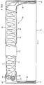
- a ribbon cartridge and self adjusting, low torque ribbon drive system includes a housing 10 having a top 12, a bottom 14 and a plurality of side members 16 extending between the top and the bottom.
- a ribbon chamber 18 is disposed in the housing between a ribbon outlet 20 in communication with a first end of the ribbon chamber, and a ribbon inlet 22 in communication with a second end of the ribbon chamber.
- An endless ribbon 24 is arranged partially in the housing 10 and partially outside the housing along a ribbon path extending sequentially through the ribbon chamber 18, the ribbon outlet 20, the ribbon inlet 22 and back to the ribbon chamber. Within the ribbon chamber 18, the ribbon 24 is arranged in a semi-fan-folded fabric pack 26.
- a gear system is disposed in the housing 10 for driving the ribbon 24 along the ribbon path.
- the gear system has a plurality of spur gears including a drive gear 30 and an idler gear 32 arranged in intermeshing engagement.
- each of the gears 30 and 32 may include a plurality of gear faces 30a-c and 32a-c, respectively.
- each gear face has a compound curvilinear tooth configuration.
- This curvilinear configuration can be formed in a variety of shapes including a sinusoidal or other curved formation that imparts rolling forces on the ribbon rather than shearing forces.
- the gear tooth configuration is defined by a plurality of generally semicircular teeth 34 separated by opposing, generally semicircular gaps 36.
- the drive gear 30 and the idler gear 32 further include a secondary tooth configuration providing a compound gear tooth curvature.
- the secondary gear teeth are defined by a plurality of lobes or ribs 38 arranged about the radii of each primary gear tooth 34.
- Each primary gear tooth 34 preferably includes at least two such ribs or may include three ribs as shown in Fig. 4.
- the ribs 38 are oriented to extend generally radially from the outer surface of each primary tooth and define recesses 39 therebetween.
- Fig. 4a illustrates another preferred aspect of the invention wherein the compound curvilinear gear tooth configuration is defined by a plurality of generally semicircular teeth 34a separated by opposing, generally semicircular gaps 36a.
- the tooth configuration of Fig. 4a is similar to that of Fig. 4 except that the secondary gear tooth configuration 38a includes a single lobe or rib 38b, forming a pair of undercuts or rims 38c in the sides of the primary gear tooth 34a.
- the undercuts 38c are identical to the undercuts provided by the outside edges of the outer ribs 38 shown in Fig. 4.
- the gear tooth configuration of Fig. 4a has the same ribbon drive traction characteristics as the gear teeth of Fig. 4. More particularly, it appears that the undercuts formed by the ribs 38 and 38c, when engaged with corrresponding undercuts in an opposing gear, form pinch points that temporarily grasp or pinch the ribbon using high contact pressure as it passes between the gears.
- At least one of the gears 30 and 32 is preferably slideably mounted in the housing 10 for positioning relative to the adjacent intermeshing gear which is mounted on a fixed rotational axis.
- This configuration assists in limiting ribbon slippage during temporary increases in web tension. As indicated, such increases can be caused by a buried loop such as the loop 39 shown in Fig. 5.
- the drive gear 30 is mounted on a fixed rotational axis 40, which is preferably formed by a hole (not shown) in the bottom 14 of the housing 10.
- the fixed axis hole is sized to receive a hub 42 of the gear 30 (shown in Fig. 2), which in turn is adapted to mate with a drive shaft (not shown) on a printing device in which the ribbon cartridge is mounted.
- the slideably mounted idler gear 32 includes a hub 44 that is mounted in a slot 46 formed in the housing bottom 14. (A corresponding slot is provided in the housing top 12, but for simplicity is not shown in the figures).
- the slot 46 has a first end 48 and a second end 50.
- the first end 48 is positioned further away from the fixed axis 40 than the second end 50.
- the slot 46 is oriented so that the distance between the axis of the slot-mounted idler gear 32 and the adjacent intermeshing drive gear 30 changes as the idler gear moves from one end to the other end of the slot 46.
- the direction and angle of the slot may be selected to maximize cartridge performance in accordance with the operational characteristics desired.
- the ribbon 24 extends around a side of the slot-mounted idler gear 32 closest to the first end 48 of the slot 46, and thereafter between the idler gear 32 and the adjacent intermeshing drive gear 30.
- the idler gear 32 is urged against the drive gear 30 by the force of the ribbon 24 acting on the side of the idler gear.
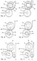
- the ribbon drive traction on the gear system is thus a function of web tension in the ribbon. As web tension increases due to a ribbon buried loop, the idler gear 32 is urged toward the drive gear 30 to decrease the distance between the gears and increase the drive traction, as shown in Fig. 7.
- the fixed gear system tested was an IBM cartridge model 4683, while the spring loaded gear system was a MX80 cartridge made by Epson. These cartridges were tested on a conventional laboratory bench test machine. As Table I illustrates, the nominal drive torque was significantly lower in the self adjusting low torque system. On the other hand, the force threshold at which drive slippage occurred was significantly higher in the low torque system than in the fixed gear and spring loaded cartridges.
- a drive gear 62 is arranged in intermeshing engagement with an idler gear 60.
- the idler gear 60 is mounted on a fixed axis 64 while the drive gear 62 has a hub 66 mounted in a slot 68.
- the gears are rotationally pulled together such that the drive gear 62 moves from the nominal position shown in Fig. 8 to the position shown in Fig. 9 in which the distance between the drive gear 62 and the idler gear 60 is decreased.
- an idler gear 70 is arranged in intermeshing engagement with a drive gear 72 and a ribbon guide 74 which may be a fixed guide post or a roller.
- the idler gear 70 includes a hub 76.
- the drive gear 72 is mounted on a fixed axis 78.
- the ribbon guide 74 is mounted on a fixed axis 80.
- the idler gear hub 76 is mounted in a slot 82.
- a novel ribbon cartridge with a self adjusting, low torque ribbon drive system has been described.
- This system requires fewer parts than conventional systems and eliminates manufacturing tolerances as a cause of poor performance or cartridge failures.
- the drive system is self adjusting and self compensating. This reduces drive torque and provides smoother rotation, better fabric pack and eliminates ribbon slippage.
- the design also permits a wide range of fabric calipers to be used. Moreover, fabric back tension can be reduced as floating gears equalize fabric tension and cause no puckering of the ribbon fabric during rotation, even with little web tension applied to the fabric or with various calipers of fabric.
- the curvilinear gear tooth configuration applies concentrated rolling forces with high contact pressure on the ribbon rather than shearing forces.
- the ribs or lobes on the gear teeth also cause higher contact pressure on the ribbon fabric to maintain and/or increase pulling traction throughout the 360 degrees of rotation.
- two or more ribs of each gear tooth will always be in contact with the ribbon fabric thus causing pinch points to advance the fabric.
- the primary and secondary gear teeth can be easily formed in numerous patterns and configurations to adjust the operating forces in the drive system. As indicated, the system operating forces can also be controlled by altering the floating gear slot angle and direction.
- the floating gear slot further allows the floating gear to cam partly out of proper mesh and lock the gears, preventing manual backward rotation.
Landscapes
- Impression-Transfer Materials And Handling Thereof (AREA)
Applications Claiming Priority (6)
| Application Number | Priority Date | Filing Date | Title |
|---|---|---|---|
| US98500292A | 1992-12-02 | 1992-12-02 | |
| US985002 | 1992-12-02 | ||
| US98933992A | 1992-12-11 | 1992-12-11 | |
| US989339 | 1992-12-11 | ||
| US15342 | 1993-02-09 | ||
| US08/015,342 US5354138A (en) | 1992-12-02 | 1993-02-09 | Self adjusting, low torque ribbon drive system |
Publications (2)
| Publication Number | Publication Date |
|---|---|
| EP0601685A2 true EP0601685A2 (de) | 1994-06-15 |
| EP0601685A3 EP0601685A3 (de) | 1994-10-26 |
Family
ID=27360315
Family Applications (1)
| Application Number | Title | Priority Date | Filing Date |
|---|---|---|---|
| EP19930303279 Withdrawn EP0601685A3 (de) | 1992-12-02 | 1993-04-27 | Getriebesystem und Druckbandkassette hiermit. |
Country Status (2)
| Country | Link |
|---|---|
| US (1) | US5354138A (de) |
| EP (1) | EP0601685A3 (de) |
Cited By (1)
| Publication number | Priority date | Publication date | Assignee | Title |
|---|---|---|---|---|
| WO1995032870A1 (en) * | 1994-05-26 | 1995-12-07 | Baltea S.P.A. | Printing ribbon feeding device |
Families Citing this family (2)
| Publication number | Priority date | Publication date | Assignee | Title |
|---|---|---|---|---|
| CA2107746A1 (en) * | 1992-10-06 | 1994-04-07 | Masahiko Nunokawa | Tape printing device and tape cartridge used therein |
| JPH0839911A (ja) * | 1994-07-28 | 1996-02-13 | Fujitsu Ltd | リボン走行装置 |
Family Cites Families (10)
| Publication number | Priority date | Publication date | Assignee | Title |
|---|---|---|---|---|
| US4213716A (en) * | 1978-05-15 | 1980-07-22 | General Electric Company | Ribbon stripping mechanism |
| GB2064476B (en) * | 1979-11-29 | 1983-08-10 | Itt Creed | Ink ribbon cassette |
| US4372697A (en) * | 1981-06-22 | 1983-02-08 | International Business Machines Corporation | Ribbon drive arrangement for a printer |
| JPS59164179A (ja) * | 1983-03-08 | 1984-09-17 | Tokyo Electric Co Ltd | プリンタのリボン送り装置 |
| US4523868A (en) * | 1983-07-18 | 1985-06-18 | International Business Machines Corporation | Ribbon feed cartridge |
| JPS60167846A (ja) * | 1984-02-06 | 1985-08-31 | Yoshida Kogyo Kk <Ykk> | 低張力による移送装置 |
| US4552473A (en) * | 1984-10-15 | 1985-11-12 | Scm Corporation | Ribbon feed mechanism |
| IT1187942B (it) * | 1986-02-28 | 1987-12-23 | Olivetti & Co Spa | Cartucce per nastro inchiostrato con dispositivo di reinchiostrazione |
| DE3824664C1 (en) * | 1988-07-20 | 1989-11-30 | Turbon International Gmbh, 5600 Wuppertal, De | Ink-ribbon cartridge |
| JPH08472B2 (ja) * | 1989-03-13 | 1996-01-10 | 株式会社精工舎 | リボンカセット |
-
1993
- 1993-02-09 US US08/015,342 patent/US5354138A/en not_active Expired - Lifetime
- 1993-04-27 EP EP19930303279 patent/EP0601685A3/de not_active Withdrawn
Cited By (2)
| Publication number | Priority date | Publication date | Assignee | Title |
|---|---|---|---|---|
| WO1995032870A1 (en) * | 1994-05-26 | 1995-12-07 | Baltea S.P.A. | Printing ribbon feeding device |
| US5820278A (en) * | 1994-05-26 | 1998-10-13 | Olivetti Lexikon S.P.A. | Printing ribbon feeding device |
Also Published As
| Publication number | Publication date |
|---|---|
| EP0601685A3 (de) | 1994-10-26 |
| US5354138A (en) | 1994-10-11 |
Similar Documents
| Publication | Publication Date | Title |
|---|---|---|
| US7165765B2 (en) | Sheet feeding apparatus and recording apparatus | |
| US5915862A (en) | Paper feed method and apparatus for a printer using a main body flap and movable insulating and guide cover | |
| DE69116258T2 (de) | Blattzuführapparat | |
| US5486854A (en) | Ink jet recording apparatus | |
| HK1006551B (en) | Screw-driving device | |
| CA1127106A (en) | Reversible ribbon cartridge for a high speed impact printer | |
| US5678936A (en) | Printer with head gap adjusting mechanism | |
| EP0601685A2 (de) | Getriebesystem und Druckbandkassette hiermit | |
| US4773773A (en) | Printer equipped with a mechanism for locking the carriage of a printing head | |
| DE69525691T2 (de) | Blattzuführvorrichtung | |
| US4732499A (en) | Ribbon cartridge for printers | |
| EP0391693A2 (de) | Papierzuführungsvorrichtung | |
| EP0521879B1 (de) | Antriebssystem mit variabler übersetzung | |
| US4654673A (en) | Thermal printer with graduated cam actuation | |
| US4394949A (en) | Pin wheel feed mechanism | |
| DE69214538T2 (de) | Mehrfarbenthermodrucker | |
| JPH10305954A (ja) | インクジェット式記録装置 | |
| EP0443444A2 (de) | Drucker mit mehreren Einbauvorrichtungen für die Traktoren | |
| US4534667A (en) | Drive mechanisms for inked ribbon cassettes | |
| EP0924093B1 (de) | Gerät zum Zuführen eines Aufzeichnungspapiers in einen Tintenstrahldrucker | |
| AU717821B2 (en) | Improved chain and casement window opening and closing mechanisms incorporating same | |
| US20060256156A1 (en) | Ink jet recording apparatus | |
| JP4336948B2 (ja) | 液体噴射間隔切換装置、キャリッジ、液体噴射装置 | |
| US20220227592A1 (en) | Peripheral device with gear train protection | |
| US5181641A (en) | Tractor feed for perforated webs |
Legal Events
| Date | Code | Title | Description |
|---|---|---|---|
| PUAI | Public reference made under article 153(3) epc to a published international application that has entered the european phase |
Free format text: ORIGINAL CODE: 0009012 |
|
| AK | Designated contracting states |
Kind code of ref document: A2 Designated state(s): DE FR GB IT |
|
| PUAL | Search report despatched |
Free format text: ORIGINAL CODE: 0009013 |
|
| AK | Designated contracting states |
Kind code of ref document: A3 Designated state(s): DE FR GB IT |
|
| 17P | Request for examination filed |
Effective date: 19950418 |
|
| 17Q | First examination report despatched |
Effective date: 19960621 |
|
| GRAG | Despatch of communication of intention to grant |
Free format text: ORIGINAL CODE: EPIDOS AGRA |
|
| GRAH | Despatch of communication of intention to grant a patent |
Free format text: ORIGINAL CODE: EPIDOS IGRA |
|
| STAA | Information on the status of an ep patent application or granted ep patent |
Free format text: STATUS: THE APPLICATION IS DEEMED TO BE WITHDRAWN |
|
| 18D | Application deemed to be withdrawn |
Effective date: 19970507 |