EP0601731A2 - Extension de bride pour doublure de tambour détachable de l'extérieur - Google Patents
Extension de bride pour doublure de tambour détachable de l'extérieur Download PDFInfo
- Publication number
- EP0601731A2 EP0601731A2 EP93309294A EP93309294A EP0601731A2 EP 0601731 A2 EP0601731 A2 EP 0601731A2 EP 93309294 A EP93309294 A EP 93309294A EP 93309294 A EP93309294 A EP 93309294A EP 0601731 A2 EP0601731 A2 EP 0601731A2
- Authority
- EP
- European Patent Office
- Prior art keywords
- drum
- seal tube
- flange
- main body
- lip
- Prior art date
- Legal status (The legal status is an assumption and is not a legal conclusion. Google has not performed a legal analysis and makes no representation as to the accuracy of the status listed.)
- Withdrawn
Links
Images
Classifications
-
- B—PERFORMING OPERATIONS; TRANSPORTING
- B65—CONVEYING; PACKING; STORING; HANDLING THIN OR FILAMENTARY MATERIAL
- B65D—CONTAINERS FOR STORAGE OR TRANSPORT OF ARTICLES OR MATERIALS, e.g. BAGS, BARRELS, BOTTLES, BOXES, CANS, CARTONS, CRATES, DRUMS, JARS, TANKS, HOPPERS, FORWARDING CONTAINERS; ACCESSORIES, CLOSURES, OR FITTINGS THEREFOR; PACKAGING ELEMENTS; PACKAGES
- B65D39/00—Closures arranged within necks or pouring openings or in discharge apertures, e.g. stoppers
- B65D39/08—Threaded or like closure members secured by rotation; Bushes therefor
- B65D39/082—Bung-rings and bungs for bung-holes
- B65D39/086—Separated bung-rings made by several elements
-
- B—PERFORMING OPERATIONS; TRANSPORTING
- B21—MECHANICAL METAL-WORKING WITHOUT ESSENTIALLY REMOVING MATERIAL; PUNCHING METAL
- B21D—WORKING OR PROCESSING OF SHEET METAL OR METAL TUBES, RODS OR PROFILES WITHOUT ESSENTIALLY REMOVING MATERIAL; PUNCHING METAL
- B21D51/00—Making hollow objects
- B21D51/16—Making hollow objects characterised by the use of the objects
- B21D51/38—Making inlet or outlet arrangements of cans, tins, baths, bottles, or other vessels; Making can ends; Making closures
- B21D51/40—Making outlet openings, e.g. bung holes
-
- B—PERFORMING OPERATIONS; TRANSPORTING
- B65—CONVEYING; PACKING; STORING; HANDLING THIN OR FILAMENTARY MATERIAL
- B65D—CONTAINERS FOR STORAGE OR TRANSPORT OF ARTICLES OR MATERIALS, e.g. BAGS, BARRELS, BOTTLES, BOXES, CANS, CARTONS, CRATES, DRUMS, JARS, TANKS, HOPPERS, FORWARDING CONTAINERS; ACCESSORIES, CLOSURES, OR FITTINGS THEREFOR; PACKAGING ELEMENTS; PACKAGES
- B65D25/00—Details of other kinds or types of rigid or semi-rigid containers
- B65D25/14—Linings or internal coatings
- B65D25/18—Linings or internal coatings spaced appreciably from container wall
Definitions
- the present invention relates in general to drum liner technology wherein a barrier film or bag is used to separate the contents within the liner from the drum material. More specifically the present invention relates to a flange extension for use with an externally detachable drum liner.
- EDDL EDDL
- Another important consideration with this technology is how to secure the liner in position relative to the drum or container so that the liner can be easily attached, the liner bag filled with the desired chemical contents, and thereafter emptied and removed without a risk that the drum or container will become contaminated.
- the approach described by Mr. Larson in his article and in his issued U.S. Patent focuses on a 55-gallon metal, open head drum and the concept of attaching the liner to the center of the lid of the drum.
- the drum lid is formed with a raised metal boss with an inwardly opening clearance channel or groove into which a drum plug flange is installed.
- a seal tube welded or soldered to the drum plug flange is used to receive a bag flange with the liner bag attached.
- a bag support sleeve is disposed around the seal tube and an O-ring is used to retain the EDDL to the drum lid in a way that allows the EDDL to be sealed closed and easily detached from the lid prior to removing the lid from the drum.
- the present flange extension invention is directed to the design of the drum plug flange and seal tube components which are part of the assembly securing the liner to the lid of the drum.
- the value of the present flange extension invention, other than being suitable for use with the described EDDL system is its lower cost, the elimination of special flange inventories and the ability to withstand the greater heat which may be present during reconditioning of the drums.
- a flange fitting for attaching to the lid of a drum comprises a seal tube having a generally cylindrical main body and an outwardly radiating, frustoconical lip extension and a drum plug flange having a generally cylindrical main body and an outwardly radiating, frustoconical lip, the drum plug flange being sized and shaped to fit within the seal tube such that the lip extension and the lip are generally coextensive with each other.
- One object of the present invention is to provide an improved flange fitting for attaching to the lid of a drum.
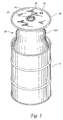
- FIG. 1 is a front elevational view of a drum, a drum lid separated from the drum and a detachable drum liner secured to the lid by means of a flange fitting according to the present invention.
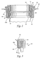
- FIG. 2 is a front elevational view in full section of a liner rim assembly assembled to the FIG. 1 flange fitting, showing the liner bag in partial form.
- FIG. 3 is a partial, side elevational view in full section of the FIG. 2 liner rim assembly.
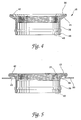
- FIG. 4 is a side elevational view in full section of the flange fitting of FIG. 1 according to the present invention.
- FIG. 5 is a side elevational view in full section of the FIG. 4 flange fitting as installed in the FIG. 1 drum lid, prior to installation of the liner rim assembly.
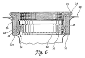
- FIG. 6 is a side elevational view in full section of the FIG. 2 liner and lid assembly with the drum plug removed and a bag plug installed.
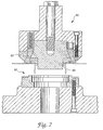
- FIG 7 is a diagrammatical illustration of the punch press operation which securely attaches the flange fitting of the present invention into the drum lid.
- FIG. 1 there is illustrated a drum lid 20 being lifted off of a 55-gallon metal drum 21 to reveal an externally detachable drum liner (EDDL) 22.
- the drum liner 22 includes a flexible plastic bag 22a which is attached at the center of the drum lid to a raised, generally cylindrical boss 23.
- Drum liner 22 includes a rigid rim assembly 24 and securing the rim assembly 24 of the drum liner 22 and the lid 20 together is a flange fitting 25 (see FIG. 2).
- Flange fitting 25 is designed such that the drum liner 22 can be detached from the lid prior to removing the lid from the drum.
- the drum lid 20 includes a standard 3/4" vent plug 28 located in its normal position near the rim 29 of the lid 20.
- FIG. 2 the assembly of the drum liner rim assembly 24 and the flange fitting 25 is illustrated in greater detail as a full cross-sectional view.
- a generally cylindrical rubber sleeve 32 is employed in the assembly of the drum liner to the raised boss.
- Sleeve 32 fits around the outer wall surface of flange fitting 25 and functions more as a filler or spacer in order to prevent any portion of the liner bag 22a from interfering with the snap fit assembly of the rim assembly 24 and flange fitting 25.
- Rim assembly 24 includes an annular bag flange 33 including a lower, outwardly radiating underside surface 35 to which bag 22a is heat sealed. As is illustrated in FIG. 3, bag 22a extends up and across underside surface 35 of bag flange 33 at which point it is heat sealed so as to create a liquid tight and secure assembly of the liner bag 22a and bag flange 33.
- Sleeve 32 has also been illustrated in FIG. 3 simply to show how the outer lip of bag 22a extends up and around the outside surface of sleeve 32 thereby spacing it from the remainder of the rim assembly 24 and flange fitting 25.
- the flange fitting 25 (see FIG. 4) includes annular drum plug flange 38 and generally cylindrical seal tube 39. These two members have a generally concentric, close fitting but free relation to each other.
- the seal tube 39 includes an O-ring channel 40 and a frustoconical lip extension 41.
- the generally cylindrical main body portion of seal tube 39 is of a unitary construction with the frustoconical lip extension 41.
- the drum plug flange 38 also includes a generally cylindrical main body portion which is internally threaded for the receipt of a drum plug and is of unitary construction with the main body portion is an upwardly and outwardly radiating frustoconical lip 42.
- the flange 38 constitutes what the inventors regard as the normal or standard flange which is typically used with containers and drums of the type illustrated and is typically anchored into the raised boss by a punch press operation including both vertically compression and inwardly directed radial jaws as illustrated in FIG. 7.
- the lip extension 41 is sized and arranged to fit closely up and around the frustoconical lip 42 of the drum plug flange.
- the lip of the drum plug flange and the lip extension of the seal tube are closely sized to one another with a free, though close fit such that the lip and lip extension are coextensive with each other.
- the upper outer edges of the lip and lip extension are adjacent with really no overlap by either member relative to the other.
- both the drum plug flange and the seal tube will be installed into the inwardly opening channel or recess in the raised boss and by means of the normal punch press operation including both vertical compressive forces and inwardly directed radial clamping forces, these two members will be locked together, simultaneously, into the raised boss.
- drum plug flange 38 and seal tube 39 without those parts having to be fixed together in some preliminary relationship. These two members do not have to be initially bonded, soldered, welded or otherwise attached to each other. All that is required is that the drum plug flange be set down inside the seal tube so that the frustoconical lip 42 of the flange and the lip extension 41 of the seal tube are oriented so as to be coextensive with each other. It will also be noted that the outer edge of the frustoconical lip is formed with a series of outwardly radiating projections, equally spaced with recess notches inbetween.
- the radial clamping forces which occur simultaneously with the vertical compressive forces as part of the punch press operation utilize these indentations in order to securely attach the flange and seal tube into the raised boss in a secure manner such that these components are not able to turn or rotate in the raised boss.
- This first assembly step creates the structure that is illustrated in FIG. 5.
- Another preliminary step which may be performed at any time relative to the timing of the punch press operation is to assemble the bag 22a to the bag flange so as to create rim assembly 24. It is of course important to first install the bag support sleeve 32 over the seal tube so that this sleeve will be in position when rim assembly 24 is snapped into position.
- an O-ring 46 is used to control the assembly and the detachable nature of the rim assembly from the flange fitting.
- O-ring 46 could be regarded as part of rim assembly 24 since the O-ring 46 is installed in the bag flange 33 prior to snapping the rim assembly 24 into the flange fitting 25.
- O-ring 46 fits within annular channel 47 (see FIG. 3) which is formed in bag flange 33.
- the seal tube 39 includes the O-ring channel ring 40 and the assembly process involves pushing upwardly on the rim assembly, including O-ring 46 so that the outer edge of the O-ring 46 slides along the inside diameter surface of the seal tube until such time as the O-ring 46 encounters the O-ring channel 40. At this point the O-ring 46 effectively snaps into the O-ring channel 40 and the rim assembly is now assembled to the flange fitting 25.
- the lower, generally cylindrical end 48 of the seal tube extends downwardly below the O-ring 46 but is sized such that the bottom edge of the seal tube does not bottom out on the top surface 49a of lower lip 49 of bag flange 33 before the O-ring 46 snaps into position in O-ring channel 40.
- bag support sleeve 32 has a length in the axial direction which does not interfere with the assembly process.
- the next step in the assembly procedure is to assembly the lid onto the drum.
- the vent plug 28 is opened (removed) and the bag 22a is inflated by means of a low pressure, high volume air pump, such as a shop vacuum blower.
- the bag is sized large enough that the drum contents are restricted only by the drum and not by any portion of the bag. This oversizing of the bag so as to eliminate any loading on the bag and thus any loading on the rim assembly/flange fitting assembly is important because the only assembly feature which holds the bag in position is the interfit of the O-ring 46 between the O-ring channel 40 in the seal tube and the O-ring channel 47 in the bag flange 33.
- the vent plug is closed (installed) and the drum is ready to be filled.
- an externally threaded drum plug 50 is received by the internal threads of the drum plug flange 38 in order to seal the drum closed after filling.
- Gasket 51 provides additional security for the seal.
- Plug 50 provides the means of opening and closing the drum as some or all of the drum contents are required.
- the drum liner EDDL
- the drum liner can then be detached from the flange fitting by exerting a downward force of approximately 45 pounds around the upper, outer edge of the bag plug 52.
- the exerted forces on the bag plug 52 press down on the upper edge of the O-ring channel 47 causing the bag flange 33 to come out of engagement with the seal tube.
- the result is that the rim assembly including the O-ring 46 will be disassembled and actually detached from the flange fitting. Consequently, the drum liner will be detached from the drum lid and is effectively free within the drum 21.
- the next step is to remove the drum lid from the drum and then dispose of the contaminant-residue trapped in the liner bag 22a as the entire liner 22 is discarded.
- the lid 20 and drum 21 are then ready to receive a new liner with the same snap fit O-ring assembly technique.
- the drum can be used and reused and reused, without the risk of chemical or hazardous waste contamination. Disposing of 100 liners as compared to 100 drums results in a dramatic decrease in hazardous waste and a dramatic decrease in storage or landfill requirements.
- flange fitting 25 The design efficiency provided by flange fitting 25 is the focus of the present invention.
- the original design for the flange fitting used a roll formed seal tube soldered (or welded) to a standard drum flange.
- the standard drum flange was then mechanically affixed to the drum head (raised boss) by the normal or conventional punch press operation.
- the raised boss includes an inwardly opening recess 56 into which the flange lip is installed.
- the upper outwardly extending lip of the standard drum flange would be anchored in position within the annular recess 56 by both vertical compression during the punch press operation while at the same time five radially positioned jaws press inwardly so as to securely lock the metal of the raised boss of the lid in and around the various projections and recesses in the outer edge of the flange lip. It is acknowledged that this earlier design and the corresponding punch press operation are conventional and typical of what has been done with this type of standard drum flange for a number of years.
- the seal tube had to be attached to the drum plug flange by some means and the method selected was welding or soldering in order to initially join these two components together so that the seal tube would have a secure and fixed relationship to the drum plug flange and the drum plug flange would then be anchored into the raised boss.
- This welding or soldering step for joining the seal tube and drum flange together had to be performed before a drum manufacturer would assemble the drum plug flange to the drum lid. Since drum manufacturers prefer not to perform this welding or soldering step and since many of the drum manufacturers are not equipped to perform this step, this original design resulted in a double inventory of drum flanges.
- Another disadvantage of the original design approach pertains to the material thickness needed for the seal tube and the fact that tube stock had to be used.
- the tube stock used is rolled and a bulging die is used to create the O-ring channel 40.
- This tube stock is substantially thicker than what is used in the present invention, having a wall thickness of approximately 0.060 inches or slightly thicker. This thickness of material is necessary because of the welding step and a concern about warpage of the steel tube and flange. With thicker material there is less risk of warpage to an unacceptable level. Warpage of the seal tube might also warp or distort the drum plug flange which could affect the internal threads.
- Warpage of the seal tube might also affect the degree of cylindricity of the seal tube and the ability of the O-ring channel 40 to properly receive the O-ring 46 in order to assemble the rim assembly 24 into the flange fitting.
- a third concern pertains to reconditioning of the drums. Reconditioning of a drum typically exposes the lid and the assembled seal tube and flange to temperatures in the range of 500 - 900° F. If solder is used as the "welding" medium in order to join the seal tube and flange together, the solder softening temperature in the range of 400 - 450° F would present a problem during drum reconditioning.
- the present invention provides improvement in the design of the flange fitting assembly by eliminating any welding or soldering step and simply crimping both the seal tube 39 and drum plug flange 38 into the raised boss 23, simultaneously by a single punch press operation.
- the present invention still uses the standard drum plug flange and thus drum manufacturers can stock a single flange for both EDDL drums and for non-EDDL drums.
- the seal tube is now able to be made of thinner sheet stock material and stamped out of the sheet stock prior to forming.
- a typical wall thickness for this sheet stock for the seal tube of the present invention is 0.028 inches.
- the O-ring channel 40 can be formed into the sheet stock and a bulging die is not required. Reconditioning temperatures are not a factor with this new design according to the present invention as there is no solder to soften and warpage is not a concern since welding temperatures are not present.
- the key feature of the present invention which is different from the original design approach is to modify the seal tube from a generally cylindrical member to a combination of a generally cylindrical member with an integral, upwardly and outwardly radiating frustoconical lip extension 41 which is sized and shaped to fit closely around and conform to the size and shape of flange 38 and in particular to the frustoconical lip 42 of flange 38.
- These two overlapping and aligned lips are installed together, though as loose pieces, into the annular recess 56 of the raised boss 23.
- the lip 42 and lip extension 41 are positioned in contact with each other and are sized and shaped so as to be coextensive with each other.
- the punch press operation of FIG. 7 is then performed securely clamping the flange and seal tube simultaneously into the raised boss of the drum lid 20.
- the punch press set up includes a movable male portion 60 and a stationary female portion 61. Located as part of the male poriton are a total of five crimping arms 62 which are equally spaced around male portion 60. Each arm 62 is spring biased and has a geometry and orientation which results in radially inward movement as the male portion advances. These arms must move inwardly to create clearance for the arms to move upwardly as the male portion advances.
- Central die 63 compresses the top surface of the raised boss 23 so as to crimp the lip 42 and lip extension 41 into the open recess 56. As this action occurs, the five arms push inwardly so as to create an underside surface of the raised boss around the lip and lip extension. This underside crimping action of the arms also crimps the metal of the raised boss 23 into and around the various projections and recesses in the flange lip.
Landscapes
- Engineering & Computer Science (AREA)
- Mechanical Engineering (AREA)
- Rigid Containers With Two Or More Constituent Elements (AREA)
- Closures For Containers (AREA)
- Pressure Vessels And Lids Thereof (AREA)
Applications Claiming Priority (2)
| Application Number | Priority Date | Filing Date | Title |
|---|---|---|---|
| US987198 | 1992-12-08 | ||
| US07/987,198 US5379913A (en) | 1992-12-08 | 1992-12-08 | Flange extension for externally detachable drum liner |
Publications (2)
| Publication Number | Publication Date |
|---|---|
| EP0601731A2 true EP0601731A2 (fr) | 1994-06-15 |
| EP0601731A3 EP0601731A3 (fr) | 1995-02-22 |
Family
ID=25533096
Family Applications (1)
| Application Number | Title | Priority Date | Filing Date |
|---|---|---|---|
| EP93309294A Withdrawn EP0601731A3 (fr) | 1992-12-08 | 1993-11-22 | Extension de bride pour doublure de tambour détachable de l'extérieur. |
Country Status (6)
| Country | Link |
|---|---|
| US (1) | US5379913A (fr) |
| EP (1) | EP0601731A3 (fr) |
| JP (1) | JPH06247446A (fr) |
| AU (1) | AU5191093A (fr) |
| CA (1) | CA2103482C (fr) |
| MX (1) | MX9307556A (fr) |
Families Citing this family (18)
| Publication number | Priority date | Publication date | Assignee | Title |
|---|---|---|---|---|
| US5697515A (en) * | 1994-12-22 | 1997-12-16 | State Industries, Inc. | Tank and tank connector assembly |
| AU724818B2 (en) * | 1995-07-26 | 2000-09-28 | Dux Manufacturing Limited | Method of mounting a device adjacent an opening of a tank |
| US5862936A (en) * | 1996-09-27 | 1999-01-26 | Sonoco Products & Company | Bung for a pressure vessel |
| NZ513489A (en) | 1999-02-16 | 2002-12-20 | Alliant Techsystems Inc | Closure assembly for lined tanks, and vehicles equipped with the same |
| US6216907B1 (en) | 1999-12-13 | 2001-04-17 | Joseph Gilles Morneau | Drum liner system |
| AU2003218328A1 (en) * | 2002-03-25 | 2003-10-13 | Tuscarora Incorporated | Insulated shipping container |
| US6758092B2 (en) * | 2002-10-30 | 2004-07-06 | Oil-Rite Corporation | Fluid level verification apparatus |
| US20050056650A1 (en) * | 2003-09-17 | 2005-03-17 | Heather Cochrane | Device for holding a collection bag |
| US20080128439A1 (en) * | 2004-02-06 | 2008-06-05 | Han-Chin Lai | Sealing mechanism for diaphragm tank |
| US7513387B2 (en) * | 2004-06-08 | 2009-04-07 | Rieke Corporation | Closure assembly for a container |
| US7464830B2 (en) * | 2004-06-08 | 2008-12-16 | Rieke Corproation | Closure assembly for a container |
| US7476358B2 (en) * | 2005-11-29 | 2009-01-13 | General Electric Company | Method and apparatus for boltless heat treatment of thin flanges |
| US20080251515A1 (en) * | 2007-04-12 | 2008-10-16 | Baughman Gary M | Container and lid combination with a sealing gasket and closing ring |
| US20090102130A1 (en) * | 2007-09-26 | 2009-04-23 | Colt Defense, Llc | Portable firing berm |
| US9578765B2 (en) * | 2008-07-25 | 2017-02-21 | Robroy Industries, Inc. | Hole plug device |
| US9557206B2 (en) | 2013-10-28 | 2017-01-31 | Oil-Rite Corporation | Adjustable fluid level verification apparatus |
| ITUB20150975A1 (it) * | 2015-05-28 | 2016-11-28 | Zilmet S P A | Vaso di espansione con raccordo migliorato |
| EP3127735B1 (fr) * | 2015-08-07 | 2017-07-05 | Magna Steyr Fuel Systems GesmbH | Manchon de remplissage de réservoir pour un véhicule ayant une résistance améliorée à la diffusion |
Family Cites Families (28)
| Publication number | Priority date | Publication date | Assignee | Title |
|---|---|---|---|---|
| US583676A (en) * | 1897-06-01 | emery | ||
| US2103678A (en) * | 1935-02-09 | 1937-12-28 | Ethel H Morrison | Refrigerated shipping and/or storing vessel |
| US2224632A (en) * | 1939-05-19 | 1940-12-10 | Philip H Fuhrmann | Container |
| US2338604A (en) * | 1942-01-22 | 1944-01-04 | Silveyra Ricardo | Flexible or pliable container |
| US2989208A (en) * | 1958-04-24 | 1961-06-20 | Continental Can Co | Container and cover assembly for corrosive materials |
| US2987216A (en) * | 1959-07-10 | 1961-06-06 | Robert S Fletcher | Disposable liner for a container |
| GB1000634A (en) * | 1962-11-15 | 1965-08-11 | Leer Ind Ltd Van | Container for the packaging, the storage and the transportation of goods |
| US3167210A (en) * | 1963-04-30 | 1965-01-26 | Greig Bros Cooperage Corp | Device for securing the filler neck of a container liner to the container |
| US3443735A (en) * | 1966-07-22 | 1969-05-13 | Inland Steel Co | End construction for shipping containers |
| US3432070A (en) * | 1967-08-16 | 1969-03-11 | Greif Bros Cooperage Corp | Drum liner with flexible neck |
| US3698595A (en) * | 1969-12-22 | 1972-10-17 | Norman Gortz | Pressurized dispenser |
| US3918605A (en) * | 1974-04-15 | 1975-11-11 | Calvin J Butler | Combination container with disposable closure and linear assembly |
| US3924773A (en) * | 1974-05-01 | 1975-12-09 | Nelson C Wilkinson | Fuel tank |
| US4164304A (en) * | 1978-05-30 | 1979-08-14 | The Continental Group, Inc. | Closure for steel drums with blow molded liners |
| DE3240225C2 (de) * | 1982-10-29 | 1984-08-30 | Automation Industrielle S.A., Vouvry | Verpackungstube |
| US4635814A (en) * | 1983-09-16 | 1987-01-13 | Rheem Manufacturing Company | Lined receptacles |
| US4552166A (en) * | 1984-04-06 | 1985-11-12 | Dc Technologies, Inc. | Secondary containment system and method |
| US4759459A (en) * | 1985-01-17 | 1988-07-26 | Ford Motor Company | Fillable tank with filler pipe retainer |
| US4653663A (en) * | 1985-10-09 | 1987-03-31 | Dayco Products, Inc. | Clamping assembly for securing a flexible liner to a storage tank, and method therefor |
| US5056680A (en) * | 1987-07-17 | 1991-10-15 | Sharp Bruce R | Attachment assembly for secondary containment tanks |
| US4775073A (en) * | 1987-10-01 | 1988-10-04 | Total Containment | Multi-purpose fitting system |
| US4941584A (en) * | 1987-12-03 | 1990-07-17 | Ashland Oil Inc. | Reusable plastic drum container assembly |
| US5005726A (en) * | 1988-12-22 | 1991-04-09 | Robbins Edward S | Composite container assemblies |
| DE3943028A1 (de) * | 1989-12-27 | 1991-07-04 | Duttenhoefer Gmbh Gottlieb | Kombinationsbehaelter |
| US5046634A (en) * | 1990-01-16 | 1991-09-10 | Scholle Corporation | Drum liner assembly |
| DE4008964A1 (de) * | 1990-03-20 | 1991-09-26 | Bernd Buedenbender | Behaelter mit mindestens einem einer fuelloeffnung zugeordneten, verschliessbaren rohrstutzen |
| US4993579A (en) * | 1990-03-26 | 1991-02-19 | Platte Chemical Co. | Bladder type container for toxic materials |
| US5154308A (en) * | 1991-07-19 | 1992-10-13 | Safety-Kleen Corporation | Detachable cover and drum liner for storage and transport of controlled materials |
-
1992
- 1992-12-08 US US07/987,198 patent/US5379913A/en not_active Expired - Fee Related
-
1993
- 1993-11-19 CA CA002103482A patent/CA2103482C/fr not_active Expired - Fee Related
- 1993-11-22 EP EP93309294A patent/EP0601731A3/fr not_active Withdrawn
- 1993-11-24 AU AU51910/93A patent/AU5191093A/en not_active Abandoned
- 1993-12-01 MX MX9307556A patent/MX9307556A/es unknown
- 1993-12-08 JP JP5308039A patent/JPH06247446A/ja active Pending
Also Published As
| Publication number | Publication date |
|---|---|
| JPH06247446A (ja) | 1994-09-06 |
| CA2103482A1 (fr) | 1994-06-09 |
| MX9307556A (es) | 1995-01-31 |
| US5379913A (en) | 1995-01-10 |
| AU5191093A (en) | 1994-06-23 |
| CA2103482C (fr) | 1997-02-25 |
| EP0601731A3 (fr) | 1995-02-22 |
Similar Documents
| Publication | Publication Date | Title |
|---|---|---|
| US5379913A (en) | Flange extension for externally detachable drum liner | |
| US5253773A (en) | Filler tube for liquid containers | |
| US5190181A (en) | Container with cap-type closure | |
| EP0707895B1 (fr) | Manchon pour la fixation d'une unité de pompe à une bouteille de verre | |
| WO2007030554A2 (fr) | Bouteille metallique refermable | |
| US5046634A (en) | Drum liner assembly | |
| CA2495842C (fr) | Bouchon pour contenant | |
| EP0215538B1 (fr) | Dispositif de fermeture avec des moyens de support auxiliaires | |
| WO1992009496A1 (fr) | Fermeture pour tonneau et procede de fabrication | |
| US4880580A (en) | Reusable plastic drum container assembly and process for refitting such plastic drum container assembly | |
| US5305906A (en) | Drum with plug | |
| US4135639A (en) | Closure construction | |
| US4938051A (en) | Method of forming a drum or pail closure | |
| US7513387B2 (en) | Closure assembly for a container | |
| US4189824A (en) | Method and apparatus for making closure construction | |
| CA1234361A (fr) | Fut en metal a jable cintre | |
| US5665189A (en) | Process for reconditioning of standardized plastic tight head drums | |
| JPH024060Y2 (fr) | ||
| GB2186814A (en) | Air filter for vehicles | |
| US2071971A (en) | Split-ring barrel closure construction | |
| HU218516B (hu) | Tartályszerű elem, a falában elhelyezett záróelemmel, valamint eljárás a megvalósítására | |
| EP0328582A4 (en) | Improved aerosol container closure | |
| JPH09327736A (ja) | 缶体の蓋体係止構造と係止突条の形成方法 | |
| EP0136953A2 (fr) | Procédé d'obtention d'un sertissage triple | |
| JPH0354571B2 (fr) |
Legal Events
| Date | Code | Title | Description |
|---|---|---|---|
| PUAI | Public reference made under article 153(3) epc to a published international application that has entered the european phase |
Free format text: ORIGINAL CODE: 0009012 |
|
| AK | Designated contracting states |
Kind code of ref document: A2 Designated state(s): AT BE CH DE DK ES FR GB GR IE IT LI LU MC NL PT SE |
|
| PUAL | Search report despatched |
Free format text: ORIGINAL CODE: 0009013 |
|
| AK | Designated contracting states |
Kind code of ref document: A3 Designated state(s): AT BE CH DE DK ES FR GB GR IE IT LI LU MC NL PT SE |
|
| 17P | Request for examination filed |
Effective date: 19950703 |
|
| 17Q | First examination report despatched |
Effective date: 19960723 |
|
| GRAG | Despatch of communication of intention to grant |
Free format text: ORIGINAL CODE: EPIDOS AGRA |
|
| GRAH | Despatch of communication of intention to grant a patent |
Free format text: ORIGINAL CODE: EPIDOS IGRA |
|
| 18D | Application deemed to be withdrawn |
Effective date: 19970907 |