EP0601829A2 - Connecteurs électriques - Google Patents
Connecteurs électriques Download PDFInfo
- Publication number
- EP0601829A2 EP0601829A2 EP93309812A EP93309812A EP0601829A2 EP 0601829 A2 EP0601829 A2 EP 0601829A2 EP 93309812 A EP93309812 A EP 93309812A EP 93309812 A EP93309812 A EP 93309812A EP 0601829 A2 EP0601829 A2 EP 0601829A2
- Authority
- EP
- European Patent Office
- Prior art keywords
- wire
- pair
- twisted
- wires
- conductor
- Prior art date
- Legal status (The legal status is an assumption and is not a legal conclusion. Google has not performed a legal analysis and makes no representation as to the accuracy of the status listed.)
- Granted
Links
- 239000004020 conductor Substances 0.000 claims abstract description 22
- 230000000694 effects Effects 0.000 description 6
- 230000005540 biological transmission Effects 0.000 description 2
- 230000001939 inductive effect Effects 0.000 description 2
- 230000015556 catabolic process Effects 0.000 description 1
- 238000006731 degradation reaction Methods 0.000 description 1
- 230000001066 destructive effect Effects 0.000 description 1
- 238000006073 displacement reaction Methods 0.000 description 1
- 230000005672 electromagnetic field Effects 0.000 description 1
- 230000005686 electrostatic field Effects 0.000 description 1
- 238000009413 insulation Methods 0.000 description 1
- 230000008054 signal transmission Effects 0.000 description 1
Images


Classifications
-
- H—ELECTRICITY
- H01—ELECTRIC ELEMENTS
- H01R—ELECTRICALLY-CONDUCTIVE CONNECTIONS; STRUCTURAL ASSOCIATIONS OF A PLURALITY OF MUTUALLY-INSULATED ELECTRICAL CONNECTING ELEMENTS; COUPLING DEVICES; CURRENT COLLECTORS
- H01R13/00—Details of coupling devices of the kinds covered by groups H01R12/70 or H01R24/00 - H01R33/00
- H01R13/646—Details of coupling devices of the kinds covered by groups H01R12/70 or H01R24/00 - H01R33/00 specially adapted for high-frequency, e.g. structures providing an impedance match or phase match
- H01R13/6461—Means for preventing cross-talk
- H01R13/6463—Means for preventing cross-talk using twisted pairs of wires
-
- H—ELECTRICITY
- H01—ELECTRIC ELEMENTS
- H01R—ELECTRICALLY-CONDUCTIVE CONNECTIONS; STRUCTURAL ASSOCIATIONS OF A PLURALITY OF MUTUALLY-INSULATED ELECTRICAL CONNECTING ELEMENTS; COUPLING DEVICES; CURRENT COLLECTORS
- H01R13/00—Details of coupling devices of the kinds covered by groups H01R12/70 or H01R24/00 - H01R33/00
- H01R13/646—Details of coupling devices of the kinds covered by groups H01R12/70 or H01R24/00 - H01R33/00 specially adapted for high-frequency, e.g. structures providing an impedance match or phase match
- H01R13/6461—Means for preventing cross-talk
- H01R13/6467—Means for preventing cross-talk by cross-over of signal conductors
-
- H—ELECTRICITY
- H01—ELECTRIC ELEMENTS
- H01R—ELECTRICALLY-CONDUCTIVE CONNECTIONS; STRUCTURAL ASSOCIATIONS OF A PLURALITY OF MUTUALLY-INSULATED ELECTRICAL CONNECTING ELEMENTS; COUPLING DEVICES; CURRENT COLLECTORS
- H01R24/00—Two-part coupling devices, or either of their cooperating parts, characterised by their overall structure
- H01R24/60—Contacts spaced along planar side wall transverse to longitudinal axis of engagement
- H01R24/62—Sliding engagements with one side only, e.g. modular jack coupling devices
- H01R24/64—Sliding engagements with one side only, e.g. modular jack coupling devices for high frequency, e.g. RJ 45
Definitions
- This invention relates to electrical connectors and in particular to the reduction of cross-talk between wires in telecommunications connectors.
- the term telecommunications connector used throughout includes connectors for both voice and data applications.
- cross-talk which may be defined as the voltage generated in one wire due to interference from a signal passing in an adjacent wire.
- the induced signal will have some inductive and capacitive components and will, therefore, vary with frequency.
- Cross-talk is a particular problem at higher frequencies and an especially difficult problem to control in data transmission lines as the induced cross-talk signal is a true data signal and is recognised, accepted and processed as such by the associated data processing equipment.
- the Standard Connector used in Data Communications Interfaces is the RJ 45 connector.
- the specification for this connector is defined in International Standard IEC 603-7 of the International Electrotechnical Commission.
- the RJ 45 connector available from AT & T corporation of Warren, New Jersey, USA, is a miniature connector having eight parallel contacts formed from spring wire.
- cross-talk may be reduced in communications cabling systems by twisting pairs of conductors used for a single circuit. As the current flows 'out' through one conductor and 'back' through the other, the nett interference effect of these two current flows is destructive as they are mutually cancelling; the electromagnetic and electrostatic fields induced by the outward flow will exactly cancel those induced by the return flow.
- the cross-talk between pairs 1 and 3 will be higher than that between other pairs as the contact wires for pair 1 are arranged between the contact wires for pair 3.
- the invention aims to reduce the effect of cross-talk between communications contacts.
- the invention in its various aspects resides in various arrangements which reduce the problem of cross-talk in the situations discussed.
- cross-talk arises between pairs 1 and 3 as a long section of wire for each conductor of each pair is laid in the connector in close proximity.
- a typical length is about 25 mm.
- Wire 3 induces cross-talk in wire 4 and the opposite sense of flow in wire 6 induces cross-talk in wire 5 in the opposite sense to that induced in wire 4.
- Figure 2 shows the normal twist of the wire pairs illustrated in Figure 1 according to the prior art.
- the wires of each pair are twisted one with the other.
- the first embodiment of the invention, shown in Figure 3 departs from this by twisting wire 3 from pair 3 with wire 5 from pair 1, and wire 6 from pair 3 with wire 4 from pair 1.
- This arrangement is adopted for a short length which can be determined experimentally or mathematically to cancel the cross-talk in the receptacle.
- wires may be simply crossed over and laid parallel in a similar manner to the way in which they are situated in the receptacle.
- the wires may be connected to the rear insulation displacement connector at a fixed wiring interface such that they are transposed relative to their position in the receptacle.
- wire 3 is transposed to be adjacent wire 5 and wire 4 is adjacent to wire 6.
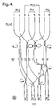
- Figure 4 shows a second embodiment of the invention, again, the eight parallel wires are numbered 1 through 8 and their standard wiring pairs are indicated above.
- wires 4 and 5 form pair 1 line 4 being the 'out' line and wire 5 the 'return'.
- Wires 1 and 2 form pair 2, wires 3 and 6 pair 3 and wires 7 and 8 pair 4. This configuration is adopted by convention although the fourth pair is sometimes omitted if not needed.
- each wire is twisted with at least two other wires, and three in the case of 4.
- the net effect is to present the wires for termination at the IDC in the correct pairs with wires of each pair being adjacent. It will be appreciated that the position of the wires of pair 1 at the IDC have been reversed, thus wire 5 is on the left of wire 4.
- wires 1 and 3 are twisted four times per unit length (P.U.L.) in a clockwise direction.
- Wires 6 and 8 are twisted twice (P.U.L.) in a counter-clockwise direction, wires 4 and 7 three times P.U.L. clockwise and wires 2 and 5 twice P.U.L. counter-clockwise.
- the relative positions of the wires is shown at A in the figure.
- Wire 4 is then twisted twice P.U.L. with wire 6 in a clockwise direction and then three times with wire 5 counter-clockwise.
- Wires 1 and 2 are twisted twice counter-clockwise, wires 3 and 6 twice clockwise and wires 7 and 8 also twice clockwise. The result is the wire configuration at the IDC and is shown at B in the figure.
- Figure 5 shows an alternative twist configuration which is set out in table 2 below.
- the wires of each pair, after twisting according to table 2 below are twisted together continuously to the edge of the connector.
- wire 1 is first twisted two twists clockwise with wire 3 whilst wire 2 is twisted with wire 5 two twists counter clockwise.
- Wires 1 and 2 are then braided in their normal configuration.
- the first recited wire is twisted over the second wire.
- wire 1 is twisted over wire 3.
- the number of twists in figure 5 is the same for each twist pair in contrast to the embodiment of figure 4.
- the twist rate is the figure 5 embodiments should be approximately 4-5 twists per inch and the twist length 9 to 12 mm measured from the jack to the V of the wires in each of the first, or previous twist pairs.
- figure 6 which shows a WE8W carrier 10 which carries eight contact wires A - H.
- the insulated wires 1 - 8 are each attached to a respective contact wire A - H and the twists occur in the region proximate the end 12 of the carrier 10 into which the insulated wires are inserted.
- the carrier and wires are mounted in a body to form a modular jack or connector.
- each wire is twisted with at least one wire from a different pair.
- Other configurations which achieve the result may be determined by those skilled in the art.
Landscapes
- Communication Cables (AREA)
Applications Claiming Priority (4)
| Application Number | Priority Date | Filing Date | Title |
|---|---|---|---|
| GB9225573 | 1992-12-07 | ||
| GB929225573A GB9225573D0 (en) | 1992-12-07 | 1992-12-07 | Electrical connectors |
| GB9226481 | 1992-12-18 | ||
| GB929226481A GB9226481D0 (en) | 1992-12-18 | 1992-12-18 | Electrical connectors |
Publications (3)
| Publication Number | Publication Date |
|---|---|
| EP0601829A2 true EP0601829A2 (fr) | 1994-06-15 |
| EP0601829A3 EP0601829A3 (fr) | 1995-08-23 |
| EP0601829B1 EP0601829B1 (fr) | 2001-10-24 |
Family
ID=26302113
Family Applications (1)
| Application Number | Title | Priority Date | Filing Date |
|---|---|---|---|
| EP93309812A Expired - Lifetime EP0601829B1 (fr) | 1992-12-07 | 1993-12-07 | Connecteurs électriques |
Country Status (2)
| Country | Link |
|---|---|
| EP (1) | EP0601829B1 (fr) |
| DE (1) | DE69330994T2 (fr) |
Cited By (4)
| Publication number | Priority date | Publication date | Assignee | Title |
|---|---|---|---|---|
| DE19708798A1 (de) * | 1997-03-05 | 1998-09-24 | Krone Ag | Anordnung von Kontaktpaaren zur Kompensation des Nahnebensprechens |
| DE19822630C1 (de) * | 1998-05-20 | 2000-09-07 | Krone Gmbh | Anordnung von Kontaktpaaren zur Kompensation des Nahnebensprechens für eine elektrische Steckverbindung |
| EP2152049A1 (fr) * | 2008-08-08 | 2010-02-10 | Alcatel Lucent | Système pour la transmission d'un signal, en particulier un signal différentiel |
| CN113922128A (zh) * | 2021-10-29 | 2022-01-11 | 西安微电子技术研究所 | 一种微型电连接器的结构及制作方法 |
Family Cites Families (5)
| Publication number | Priority date | Publication date | Assignee | Title |
|---|---|---|---|---|
| DE1083880B (de) * | 1958-06-27 | 1960-06-23 | Siemens Ag | Fernmeldekabel mit in Lagen angeordneten Einzeladern, aus denen durch gegenseitiges Kreuzen Doppelleitungen gebildet sind |
| SE326220B (fr) * | 1966-01-14 | 1970-07-20 | Ericsson Telefon Ab L M | |
| US3761842A (en) * | 1972-06-01 | 1973-09-25 | Bell Telephone Labor Inc | Twisted pair flat conductor cable with means to equalize impedance and propagation velocity |
| US4945189A (en) * | 1989-08-09 | 1990-07-31 | Palmer Donald E | Asymmetric audio cable for high fidelity signals |
| FR2652929B1 (fr) * | 1989-10-06 | 1995-04-14 | Bull Sa |
-
1993
- 1993-12-07 EP EP93309812A patent/EP0601829B1/fr not_active Expired - Lifetime
- 1993-12-07 DE DE69330994T patent/DE69330994T2/de not_active Expired - Fee Related
Cited By (6)
| Publication number | Priority date | Publication date | Assignee | Title |
|---|---|---|---|---|
| DE19708798A1 (de) * | 1997-03-05 | 1998-09-24 | Krone Ag | Anordnung von Kontaktpaaren zur Kompensation des Nahnebensprechens |
| US6017247A (en) * | 1997-03-05 | 2000-01-25 | Krone Aktiengesellschaft | Arrangement of contact pairs for compensation of near-end crosstalk |
| DE19822630C1 (de) * | 1998-05-20 | 2000-09-07 | Krone Gmbh | Anordnung von Kontaktpaaren zur Kompensation des Nahnebensprechens für eine elektrische Steckverbindung |
| US6120330A (en) * | 1998-05-20 | 2000-09-19 | Krone Gmbh | Arrangement of contact pairs for compensating near-end crosstalk for an electric patch plug |
| EP2152049A1 (fr) * | 2008-08-08 | 2010-02-10 | Alcatel Lucent | Système pour la transmission d'un signal, en particulier un signal différentiel |
| CN113922128A (zh) * | 2021-10-29 | 2022-01-11 | 西安微电子技术研究所 | 一种微型电连接器的结构及制作方法 |
Also Published As
| Publication number | Publication date |
|---|---|
| DE69330994D1 (de) | 2001-11-29 |
| DE69330994T2 (de) | 2002-07-18 |
| EP0601829B1 (fr) | 2001-10-24 |
| EP0601829A3 (fr) | 1995-08-23 |
Similar Documents
| Publication | Publication Date | Title |
|---|---|---|
| EP0858684B1 (fr) | Connecteur electrique a diaphonie reduite | |
| CA2225108C (fr) | Connecteur haute frequence offrant des caracteristiques d'annulation du bruit | |
| KR100340693B1 (ko) | 소음제거기능을가진통신용콘넥터단자열 | |
| EP0811258B1 (fr) | Ensemble cable et fiche modulaire pour radiofrequences | |
| US6602097B1 (en) | High frequency electrical connector | |
| US6065994A (en) | Low-crosstalk electrical connector grouping like conductors together | |
| US5967801A (en) | Modular plug having compensating insert | |
| US7713094B1 (en) | Telecommunications connector configured to reduce mode conversion coupling | |
| EP0856919B1 (fr) | Connecteur avec faible bruit diaphonique pour systemes de telecommunications | |
| US6036547A (en) | Double deck gang jack exhibiting suppressed mutual crosstalk | |
| CA2272012A1 (fr) | Prise destinee aux applications de communication, offrant une latence reduite de diaphonie complementaire | |
| JPH11329613A (ja) | コネクタ―・ジャック組立体 | |
| US5282754A (en) | Multi-terminal electrical connectors | |
| US5340333A (en) | Shielded modular adapter | |
| US5791942A (en) | High frequency electrical connector | |
| EP0993081B1 (fr) | Connecteur modulaire avec séparateurs capacitifs | |
| WO2004062038A9 (fr) | Systeme de connexion a fiche et bloc pour paires de contact differentiels | |
| EP1815607B1 (fr) | Configuration de contact dans un systeme de communication pour reduction de diaphonie | |
| US6099357A (en) | High frequency electrical connector for reducing crosstalk | |
| US6744329B2 (en) | Cross talk compensation circuit | |
| EP0601829B1 (fr) | Connecteurs électriques | |
| CA2420268C (fr) | Ensemble a connecteur rj de haute densite | |
| US5652553A (en) | Signal transmission between modules connected to a common backplane | |
| GB2286297A (en) | Electrical connectors | |
| GB2203904A (en) | Extended frequency range plugboard switching system |
Legal Events
| Date | Code | Title | Description |
|---|---|---|---|
| PUAI | Public reference made under article 153(3) epc to a published international application that has entered the european phase |
Free format text: ORIGINAL CODE: 0009012 |
|
| AK | Designated contracting states |
Kind code of ref document: A2 Designated state(s): DE FR GB |
|
| PUAL | Search report despatched |
Free format text: ORIGINAL CODE: 0009013 |
|
| AK | Designated contracting states |
Kind code of ref document: A3 Designated state(s): DE FR GB |
|
| 17P | Request for examination filed |
Effective date: 19960205 |
|
| 17Q | First examination report despatched |
Effective date: 19990319 |
|
| GRAG | Despatch of communication of intention to grant |
Free format text: ORIGINAL CODE: EPIDOS AGRA |
|
| GRAG | Despatch of communication of intention to grant |
Free format text: ORIGINAL CODE: EPIDOS AGRA |
|
| GRAH | Despatch of communication of intention to grant a patent |
Free format text: ORIGINAL CODE: EPIDOS IGRA |
|
| GRAH | Despatch of communication of intention to grant a patent |
Free format text: ORIGINAL CODE: EPIDOS IGRA |
|
| GRAA | (expected) grant |
Free format text: ORIGINAL CODE: 0009210 |
|
| AK | Designated contracting states |
Kind code of ref document: B1 Designated state(s): DE FR GB |
|
| PG25 | Lapsed in a contracting state [announced via postgrant information from national office to epo] |
Ref country code: FR Free format text: LAPSE BECAUSE OF FAILURE TO SUBMIT A TRANSLATION OF THE DESCRIPTION OR TO PAY THE FEE WITHIN THE PRESCRIBED TIME-LIMIT Effective date: 20011024 |
|
| REF | Corresponds to: |
Ref document number: 69330994 Country of ref document: DE Date of ref document: 20011129 |
|
| REG | Reference to a national code |
Ref country code: GB Ref legal event code: IF02 |
|
| PG25 | Lapsed in a contracting state [announced via postgrant information from national office to epo] |
Ref country code: GB Free format text: LAPSE BECAUSE OF NON-PAYMENT OF DUE FEES Effective date: 20020124 |
|
| PG25 | Lapsed in a contracting state [announced via postgrant information from national office to epo] |
Ref country code: DE Free format text: LAPSE BECAUSE OF NON-PAYMENT OF DUE FEES Effective date: 20020702 |
|
| EN | Fr: translation not filed | ||
| PLBE | No opposition filed within time limit |
Free format text: ORIGINAL CODE: 0009261 |
|
| STAA | Information on the status of an ep patent application or granted ep patent |
Free format text: STATUS: NO OPPOSITION FILED WITHIN TIME LIMIT |
|
| GBPC | Gb: european patent ceased through non-payment of renewal fee |
Effective date: 20020124 |
|
| 26N | No opposition filed |