EP0601864B1 - Cadre pour turbine - Google Patents
Cadre pour turbine Download PDFInfo
- Publication number
- EP0601864B1 EP0601864B1 EP93309926A EP93309926A EP0601864B1 EP 0601864 B1 EP0601864 B1 EP 0601864B1 EP 93309926 A EP93309926 A EP 93309926A EP 93309926 A EP93309926 A EP 93309926A EP 0601864 B1 EP0601864 B1 EP 0601864B1
- Authority
- EP
- European Patent Office
- Prior art keywords
- strut
- struts
- ring
- clevis
- casing
- Prior art date
- Legal status (The legal status is an assumption and is not a legal conclusion. Google has not performed a legal analysis and makes no representation as to the accuracy of the status listed.)
- Expired - Lifetime
Links
- 238000005304 joining Methods 0.000 claims description 9
- 230000005465 channeling Effects 0.000 claims description 5
- 238000004891 communication Methods 0.000 claims description 3
- 238000005452 bending Methods 0.000 claims description 2
- 238000007789 sealing Methods 0.000 claims description 2
- 239000000567 combustion gas Substances 0.000 description 7
- 238000001816 cooling Methods 0.000 description 7
- 239000007789 gas Substances 0.000 description 4
- 239000003921 oil Substances 0.000 description 4
- 238000005266 casting Methods 0.000 description 3
- 230000000295 complement effect Effects 0.000 description 2
- 230000006835 compression Effects 0.000 description 2
- 238000007906 compression Methods 0.000 description 2
- 239000000284 extract Substances 0.000 description 2
- 230000013011 mating Effects 0.000 description 2
- 238000012986 modification Methods 0.000 description 2
- 230000004048 modification Effects 0.000 description 2
- 230000004888 barrier function Effects 0.000 description 1
- 239000000446 fuel Substances 0.000 description 1
- 239000010687 lubricating oil Substances 0.000 description 1
- 238000005461 lubrication Methods 0.000 description 1
- 238000004519 manufacturing process Methods 0.000 description 1
- 238000000034 method Methods 0.000 description 1
- 230000035515 penetration Effects 0.000 description 1
- 238000012546 transfer Methods 0.000 description 1
Images



Classifications
-
- F—MECHANICAL ENGINEERING; LIGHTING; HEATING; WEAPONS; BLASTING
- F01—MACHINES OR ENGINES IN GENERAL; ENGINE PLANTS IN GENERAL; STEAM ENGINES
- F01D—NON-POSITIVE DISPLACEMENT MACHINES OR ENGINES, e.g. STEAM TURBINES
- F01D9/00—Stators
- F01D9/06—Fluid supply conduits to nozzles or the like
- F01D9/065—Fluid supply or removal conduits traversing the working fluid flow, e.g. for lubrication-, cooling-, or sealing fluids
-
- F—MECHANICAL ENGINEERING; LIGHTING; HEATING; WEAPONS; BLASTING
- F01—MACHINES OR ENGINES IN GENERAL; ENGINE PLANTS IN GENERAL; STEAM ENGINES
- F01D—NON-POSITIVE DISPLACEMENT MACHINES OR ENGINES, e.g. STEAM TURBINES
- F01D25/00—Component parts, details, or accessories, not provided for in, or of interest apart from, other groups
- F01D25/16—Arrangement of bearings; Supporting or mounting bearings in casings
- F01D25/162—Bearing supports
Definitions
- the present invention relates generally to gas turbine engines, and, more specifically, to frames therein for supporting bearings and shafts.
- Gas turbine engines include one or more rotor shafts supported by bearings which, in turn, are supported by annular frames.
- the frame includes an annular casing spaced radially outwardly from an annular hub, with a plurality of circumferentially spaced apart struts extending therebetween.
- the struts may be integrally formed with the casing and hub in a common casting, for example, or may be suitably bolted thereto. In either configuration, the overall frame must have suitable structural rigidity for supporting the rotor shaft to minimize deflections thereof during operation.
- frames disposed downstream of the engine's combustor are, therefore, subject to the hot combustion gases which flow downstream from the combustor and through the engine's turbine which extracts energy therefrom for rotating the shaft.
- the struts extend radially inwardly from the casing, they necessarily pass through the combustion gases and must, therefore, be suitably protected from the heat thereof.
- conventional fairings typically surround the struts for providing a barrier against the hot combustion gases, and through which fairings cooling air may be channeled for preventing elevated temperatures of the frame.
- Such a frame including fairings to protect against the combustion gases must, of course, be configured to allow the assembly thereof.
- the casing, struts, and hub are an integral cast member, and, therefore, each of the fairings must be configured for assembly around each strut.
- the fairing may be a sheetmetal structure having a radial splitline which allows the fairing to be elastically opened for assembly around a respective strut, and then the fairing is suitably joined together at its splitline to complete the assembly.
- the struts may be integrally joined at one end to either the casing or the hub, and at its other end bolted to the complementary hub or casing.
- the fairing may be an integral hollow member which can be positioned over the free end of the strut prior to joining the strut free end to its respective casing or hub.
- provisions must be provided to ensure that the joint between the strut end and the casing or hub provides suitable rigidity to ensure an overall rigid frame to suitably support the rotor shaft.
- the casing is an annular member having a plurality of radially extending generally inversely U-shaped slots which receive the strut ends.
- Conventional expansion bolts extend in generally tangential directions through the spaced apart radial legs defining the U-slot for rigidly joining the strut end to the casing.
- the expansion bolts provide zero clearance between where they pass through the strut end and the casing to ensure effective transmittal of both compression and tension loads between the strut and the casing. This arrangement allows assembly of the expansion bolts from the exterior of the casing.
- the U-slots themselves provide circumferentially spaced apart discontinuities along the circumference of the casing which interrupt the hoop stress carrying capability of the casing and, therefore, decrease the overall rigidity of the frame.
- This reduction in rigidity may be minimized by making the strut outer end as small as possible in transverse configuration, with a practical limit being the transverse configuration of the central portion of the strut itself.
- This relatively small size of the strut outer end also ensures that the fairing surrounding the strut may be made as small as possible since it must be typically assembled over the strut outer end to complete the assembly of the turbine frame. Minimizing the strut, and hence, the fairing, reduces both weight and aerodynamic penalties.
- a turbine frame having reduced size struts for reducing the size of the fairing surrounding the strut while also rigidly mounting the strut to both the casing and the hub.
- the joint therebetween should provide suitable rigidity to ensure the overall rigidity of the entire turbine frame for carrying both compression and tension loads through the struts without undesirable deflections of the hub which would affect the proper positioning of the rotor shaft supported thereby.
- hollow struts to form a common channel through the casing and the hub for channeling air therethrough or for carrying service pipes such as lube oil or scavenge oil pipes into the engine sump located below the hub. This must be done without significantly reducing the overall structural rigidity of the turbine frame due to the required apertures, or interruptions, in either the casing or the hub for carrying the airflow or service pipes therethrough.
- a turbine frame includes first and second coaxially disposed rings having a plurality of circumferentially spaced apart struts extending therebetween.
- a plurality of clevises join respective first ends of the struts to the first ring for removably joining the struts thereto.
- Each of the clevises includes a base removably fixedly joined to the first ring, and a pair of legs extending away from the base and spaced apart to define a U-shaped clevis slot receiving the strut first end.
- the strut first end is removably fixedly joined to the clevis legs by a pair of expansion bolts.
- the clevis base includes a central aperture aligned with a first port in the first ring for providing access therethrough.
- the strut first end is disposed in the clevis slot in abutting contact with the first ring through the central aperture of the clevis base for carrying compressive loads directly thereto through the strut.
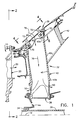
- Figure 1 is an axial, partly sectional view of a portion of a gas turbine engine showing a turbine frame in accordance with an exemplary embodiment of the present invention.
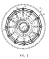
- Figure 2 is a transverse view of the turbine frame illustrated in Figure 1 taken along line 2-2.
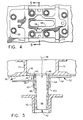
- Figure 3 is an exploded view of a portion of one of the struts and mating clevises of the turbine frame illustrated in Figure 2.
- Figure 4 is a top view of a portion of the turbine frame illustrated in Figure 1 taken along line 4-4.
- Figure 5 is a transverse, partly sectional view of the turbine frame illustrated in Figure 4 showing a strut outer end joined to the casing by the clevis and taken along line 5-5.
- Figure 6 is a bottom, partly sectional view of the strut and clevis joined to the casing illustrated in Figure 1 and taken along line 6-6.
- Figure 7 is a transverse, partly sectional view of the outer end of the strut joined to the casing by the clevis of Figure 6 taken along line 7-7.
- Figure 8 is an axial sectional view of a portion of a turbine frame in accordance with a second embodiment of the present invention illustrating service lines extending through the struts thereof.
- FIG. 1 Illustrated schematically in Figure 1 is a portion of an exemplary gas turbine engine 10 having an axial, or longitudinal centerline axis 12.
- a fan, compressor, and combustor all not shown
- HPT high pressure turbine
- LPT low pressure turbine
- a first shaft joins the compressor to the HPT 20
- a second shaft 26 joins the fan to the LPT.
- An annular turbine frame 32 in accordance with one embodiment of the present invention is provided for supporting a conventional bearing 34 which, in turn, supports one end of the second shaft 26 for allowing rotation thereof.
- the frame 32 may support the aft end of the HPT shaft (not shown).
- the turbine frame 32 is disposed downstream of the HPT 20 and, therefore, must be protected from the combustion gases 30 which flow therethrough.
- the turbine frame 32 as illustrated in Figures 1 and 2 includes a first structural ring 36, or casing for example, disposed coaxially about the centerline axis 12.
- the frame 32 also includes a second structural ring 38, or hub for example, disposed coaxially with the first ring 36 about the centerline axis 12 and spaced radially inwardly therefrom.
- a plurality of circumferentially spaced apart hollow struts 40 extend radially between the first and second rings 36 and 38 and are fixedly joined thereto.
- the frame 32 also includes a plurality of conventional fairings 42 each of which conventionally surrounds a respective one of the struts 40 for protecting the struts from the combustion gases 30 which flow through the turbine frame 32.
- Conventionally joined to the hub 38 is a conventional, generally conical sump member 44 which supports the bearing 34 in its central bore.
- Each of the struts 40 includes a first, or outer, end 40a and a radially opposite second, or inner, end 40b, with an elongate center portion 40c extending therebetween.
- the strut 40 is hollow and includes a through channel 46 extending completely through the strut 40 from the outer end 40a and through the center portion 40c to the inner end 40b.
- the casing 36 includes a plurality of circumferentially spaced apart first ports 48 extending radially therethrough, and the hub 38 (see Figure 1) similarly includes a plurality of circumferentially spaced apart second ports 50 extending radially therethrough.
- the inner ends 40b of the struts 40 are integrally formed with the hub 38 in a common casting, for example, and the outer ends 40a of the struts 40 are removably fixedly joined to the casing 36 in accordance with the present invention.
- the strut outer ends 40a may be integrally joined to the casing 36 in a common casting, for example, with the strut inner ends 40b being removably joined to the hub 38 also in accordance with the present invention.
- the turbine frame 32 further includes a plurality of clevises 52 which removably join the strut outer ends 40a to the casing 36 in the configuration illustrated in Figures 1 and 3, or removably join the inner ends 40b to the hub 38 (not shown).
- each of the clevises 52 is disposed between a respective one of the strut ends 40a, 40b and the respective ring, i.e. casing 36 or hub 38, in alignment with respective ones of the first or second ports 48, 50 for removably joining the struts 40 to the first or second ring, i.e. casing 36 or hub 38, for both carrying loads and providing access therethrough.
- each of the clevises 52 includes an arcuate base 54 disposed against the inner circumference of the casing 36, and includes a plurality of mounting holes 56, eight being shown for example, for receiving a respective plurality of mounting bolts 58, with corresponding nuts, therethrough to removably fixedly join the base 54 to the casing 36.
- the base 54 includes a central aperture 60 aligned with a respective one of the first ports 48.
- the clevis 52 also includes first and second legs 62, 64 extending radially inwardly away from the base 54 and being preferably integral therewith, which legs 62, 64 are spaced circumferentially apart and joined together at their ends to define a generally axially extending U-shaped clevis slot, or pocket 66 which receives the strut outer end 40a.
- the first and second legs 62, 64 and the strut outer end 40a have a pair of generally axially spaced apart line-drilled bores 68 extending therethrough as shown in Figures 3 and 7 which receive a respective pair of conventional expansion bolts 70 for removably fixedly joining the strut outer end 40a to the first and second legs 62, 64, with the strut through channel 46 being disposed generally axially between the two expansion bolts 70 and aligned with both the base aperture 60 and the first port 48 as shown in more particularity in Figures 5 and 6.
- the casing 36 includes a pair of axially spaced apart, annular stiffening ribs 72 disposed on opposite, axial sides of the clevises 52 and the first ports 48 for carrying loads between the struts 40 and the casing 36 without interruption by the first ports 48, for example.
- the respective stiffening ribs 72 are continuous and uninterrupted annular members which carry loads in the hoop-stress direction without interruption by either the ports 48 or the struts 40 joined to the casing 36.
- the clevis 52 preferably also includes a plurality of gussets 74 integrally joining the clevis first and second legs 62, 64 to the clevis base 54 for carrying bending loads transmitted through the strut 40 and the casing 36.
- These gussets 74 improve the rigidity of the clevis 52 while minimizing the weight thereof and allow the strut outer end 40a to be made as small as possible for minimizing the size of the fairing 42.
- the strut outer end 40a is sized substantially equal in transverse section with the strut center portion 40c, although they have generally different configurations, for allowing the strut inner end 40a to fit through a respective one of the fairings 42 during assembly.
- the fairing 42 is a one-piece cast hollow member which may be assembled with the strut 40 solely by being radially positioned downwardly over the strut outer end 40a and into position around the strut center portion 40c.
- the strut outer end 40a is generally rectangular and is about the same size as the strut center portion 40c, which is generally airfoil-shaped, to fit through the fairing 42 with minimum clearance therewith for maintaining a relatively small size of the fairing 42.
- the clevis first and second legs 62, 64 are reinforced with the gussets 74 to increase the rigidity between the strut outer end 40a when it is joined into the clevis 52.
- the strut outer end 40a is preferably disposed in the clevis slot 66 in abutting contact with the inner surface of the casing 36 through the clevis base central aperture 60 for carrying compressive loads directly thereto through the strut 40 during operation.
- the strut outer end 40a is also disposed in the clevis slot 66 in sealing arrangement with the first port 48 through the central aperture 60 for channeling airflow through the ports 48 and 50 of the casing 36 and hub 38.
- cooling air 76 is allowed to flow through the casing first ports 48 and downwardly through the central apertures 60 of the clevises 52 and in turn through the struts 40 and hub second ports 50 for conventional use inside the engine.
- the casing 36 includes a plurality of auxiliary ports 78, each auxiliary port 78 being disposed adjacent to a respective one of the first ports 48 and between the pair of casing stiffening ribs 72.
- the clevis base 54 also includes a complementary auxiliary aperture 80 spaced from the central aperture 60 on opposite sides of the first leg 62, for example, and aligned in flow communication with the auxiliary port 78. In this way the cooling airflow 76 channeled between the ribs 72 is split between the first and auxiliary ports 48 and 78 to flow separately between the central and auxiliary apertures 60 and 80 through the clevis base 54.
- an effective seal is created therewith to ensure the separate flow of the airflow 76 through the ports 48, 78 into the respective apertures 70, 80.
- compressive loads between the strut 40 and the casing 36 are directly transmitted through this abutting joint and carried by the ribs 72 for maintaining rigidity of the turbine frame 32 without significant affect by the several relatively small ports 48, 78 surrounding the casing 36 between the ribs 72.
- the struts 40 terminate inside the casing 36 and are joined thereto by the clevises 52, they do not penetrate the casing 36 as in conventional designs which decrease the effective rigidity of the frame.
- the ports 48 and 78 are relatively small as compared to the penetrations of the casing 36 which would otherwise be required for mounting the strut outer ends 40a in a conventional manner and, therefore, do not significantly decrease the rigidity of the assembled frame 32.
- the strut channel 46 is provided for directly channeling the cooling air 76 therethrough
- conventional service lines or pipes for carrying oil may be routed through the casing 36, hub 38, and corresponding struts 40 for channeling oil to and from the region of the sump 44.
- Figure 8 illustrates an alternate embodiment of the invention wherein the frame 32 is configured for carrying through the casing 36, one of the struts 40, and the hub 38, a pair of conventional service pipes 82 which carry lubrication oil, for example.
- the clevis 52 joins the routs 40 to the casing 36 as described above for obtaining improved rigidity of the turbine frame 32 while still allowing the service pipes 82 to pass through the casing 36 and through the clevis 52 for routing through the strut 40 without reducing the overall rigidity of the turbine frame 32.
- each of the clevises 52 preferably includes an axial stop or tab 84 extending axially forwardly from the base 54 as shown in Figures 1 and 3 which is predeterminedly sized to abut radially inwardly extending flange 86 of the casing 36 for accurately axially aligning all of the clevises 52, and in turn the struts 40.
- the resulting turbine frame 32 provides substantial overall rigidity even though the strut outer ends 40a are removably joined to the casing 36 using the respective clevises 52, while also providing access through the individual struts 40 for the cooling air 76 or the conventional service pipes.
- the turbine frame 32 allows an improved method of manufacture wherein the individual clevises 52 may firstly be temporarily joined to the strut outer ends 40a for allowing the bores 68 to be line-drilled therethrough for providing continuous and pre-aligned bores 68 for receiving the respective expansion bolts 70.
- the outer surface of the pre-assembled clevises 52 and the strut ends 40a may then be conventionally ground to a suitable arc for mating with the inner diameter of the casing 36.
- the clevises 52 may then be located in position in the casing 36 so that the mounting holes 56 may be line-drilled to extend also through the casing 36 for providing effective alignment of the clevis 52 therewith for receiving the mounting bolts 58.
- the clevis 52 and strut end 40a may be ground to establish an interference fit to the casing 36.
Landscapes
- Engineering & Computer Science (AREA)
- Mechanical Engineering (AREA)
- General Engineering & Computer Science (AREA)
- Physics & Mathematics (AREA)
- Fluid Mechanics (AREA)
- Turbine Rotor Nozzle Sealing (AREA)
Claims (8)
- Carter de turbine (32) comprenant:un premier anneau (36) disposé coaxialement autour d'un axe central (12) et comportant une pluralité de premiers orifices (48) espacés les uns des autres;un deuxième anneau (38) disposé coaxialement audit premier anneau (36) et espacé radialement de celui-ci, et comportant une pluralité de deuxièmes orifices (50) espacés circonférenciellement les uns des autres;une pluralité d'entretoises (40) espacées circonférenciellement les unes des autres et montées radialement entre lesdits premier et deuxième anneaux (36, 38), chaque entretoise (40) comportant des première et deuxième extrémités (40a, 40b) radialement opposées et un canal traversant (46) s'étendant entre ces dernières; etune pluralité de chapes (52), chacune desdites chapes (52) étant disposée entre celle respective desdites premières extrémités (40a) d'entretoise et ledit premier anneau (36) en alignement avec celui respectif desdits premiers orifices (48) pour raccorder de façon démontable lesdites entretoises (40) audit premier anneau (36) à la fois pour y transférer les charges et pour y assurer un accès;chacune desdites chapes (52) comprenant:une base (54) disposée contre le premier anneau (36) et comportant une pluralité de trous de montage (56) recevant des boulons de montage (58) qui les traverse pour assembler de façon fixe mais démontable ladite base (54) audit premier anneau (36), ladite base (54) comportant une ouverture centrale (60) alignée avec ledit orifice (48); etdes première et deuxième branches (62, 64) s'étendant depuis ladite base (54) et espacées circonférenciellement de manière à définir une fente en U (66) de chape, recevant ladite première extrémité (40a) d'entretoise ; lesdites première et deuxième branches (62, 64) et ladite première extrémité (40a) d'entretoise comportant une paire de trous (68) espacés l'un de l'autre et s'étendant à travers celle-ci et recevant une paire respective de boulons à expansion (70) destinés à assembler de façon fixe mais démontable ladite première extrémité (40a) d'entretoise auxdites première et deuxième branches (62, 64), ledit canal traversant (46) d'entretoise étant disposé entre ladite paire de boulons à expansion (70) et étant aligné avec à la fois ladite ouverture (60) de base et ledit premier orifice (48) etdans lequel ladite première extrémité (40a) d'entretoise est disposée dans ladite fente (66) de chape en contact de butée avec ledit premier anneau (36), à travers ladite ouverture centrale (60) de base de chape, pour y transférer directement les forces de compression par l'intermédiaire de ladite entretoise (40).
- Carter selon la revendication 1, dans lequel ledit premier anneau (36) comprend une paire de nervures annulaires de renforcement (72) espacées l'une de l'autre et disposées sur les côtés opposés de ladite chape (52) et desdits premiers orifices (48) pour transférer les charges entre lesdites entretoises (40) et ledit premier anneau (36).
- Carter selon la revendication 2, dans lequel ladite chape (52) comprend, en outre, une pluralité de goussets (74) reliant lesdites première et deuxième branches (62, 64) de chape à ladite base de chape (54) pour transférer les forces de flexion transmises par l'intermédiaire de ladite entretoise (40) et dudit anneau (36).
- Carter selon la revendication 3, dans lequelledit premier anneau (36) se présente sous la forme d'une enveloppe disposée radialement à l'extérieur par rapport auxdites entretoises (40);ledit deuxième anneau (38) se présente sous la forme d'un moyeu disposé radialement à l'intérieur par rapport auxdites entretoises (40) etlesdites chapes (52) relient de façon démontable les extrémités radialement extérieures (40A) desdites entretoises (40) à ladite enveloppe (36).
- Carter selon la revendication 4, comprenant, en outre, une pluralité de pièces de carénage (42), chaque pièce de carénage (42) entourant celle respective desdites entretoises (40), et dans lequel chacune desdites entretoises (40) comprend une partie centrale (40c), ladite première extrémité (40a) d'entretoise étant dimensionnée de manière à avoir une section transversale sensiblement égale à celle de ladite partie centrale (40c) d'entretoise pour s'ajuster dans celle respective desdites pièces de carénage (42).
- Carter selon la revendication 5, dans lequel ladite première extrémité (40a) d'entretoise est disposée dans ladite fente (66) de chape dans une disposition d'étanchéité avec ledit premier orifice (48) pour canaliser un écoulement d'air à travers lesdits premier et deuxième anneaux (36, 38) et lesdites entretoises (40).
- Carter selon la revendication 6, dans lequel:ladite enveloppe (36) comprend, en outre, une pluralité d'orifices auxiliaires (78), chaque orifice auxiliaire (78) étant disposé de façon contiguë à celui respectif desdits premiers orifices (48) et entre lesdites première et deuxième nervures de renforcement (72); etladite base (54) de chape comprend, en outre, une ouverture auxiliaire (80) espacée de ladite ouverture centrale (60) sur les côtés opposés de ladite première branche (62) et alignée de manière à établir une communication d'écoulement avec ledit orifice auxiliaire (78) de telle sorte que l'écoulement d'air canalisé entre lesdites nervures (72) se divise entre ledit premier orifice (48) et ledit orifice auxiliaire (78) pour s'écouler séparément entre ladite ouverture centrale (60) et ladite ouverture auxiliaire (80) travers ladite base (54) de chape, ledit écoulement d'air à travers ladite ouverture centrale (60) étant canalisé jusque dans ledit canal traversant (46) d'entretoise.
- Carter selon la revendication 4, comprenant, en outre:un rebord (86) s'étendant radialement vers l'intérieur depuis ladite enveloppe (36), etune patte (84) s'étendant axialement depuis chacune desdites bases (54) de chape, en contact de butée avec ledit rebord (86).
Applications Claiming Priority (2)
| Application Number | Priority Date | Filing Date | Title |
|---|---|---|---|
| US07/988,637 US5292227A (en) | 1992-12-10 | 1992-12-10 | Turbine frame |
| US988637 | 1992-12-10 |
Publications (2)
| Publication Number | Publication Date |
|---|---|
| EP0601864A1 EP0601864A1 (fr) | 1994-06-15 |
| EP0601864B1 true EP0601864B1 (fr) | 1997-07-30 |
Family
ID=25534346
Family Applications (1)
| Application Number | Title | Priority Date | Filing Date |
|---|---|---|---|
| EP93309926A Expired - Lifetime EP0601864B1 (fr) | 1992-12-10 | 1993-12-09 | Cadre pour turbine |
Country Status (4)
| Country | Link |
|---|---|
| US (1) | US5292227A (fr) |
| EP (1) | EP0601864B1 (fr) |
| JP (1) | JPH076408B2 (fr) |
| DE (1) | DE69312657T2 (fr) |
Families Citing this family (122)
| Publication number | Priority date | Publication date | Assignee | Title |
|---|---|---|---|---|
| US5438756A (en) * | 1993-12-17 | 1995-08-08 | General Electric Company | Method for assembling a turbine frame assembly |
| US5609467A (en) * | 1995-09-28 | 1997-03-11 | Cooper Cameron Corporation | Floating interturbine duct assembly for high temperature power turbine |
| CN1106496C (zh) * | 1996-06-21 | 2003-04-23 | 西门子公司 | 涡轮轴及其冷却方法 |
| US5746574A (en) * | 1997-05-27 | 1998-05-05 | General Electric Company | Low profile fluid joint |
| US6045312A (en) * | 1999-03-17 | 2000-04-04 | Illinois Tool Works Inc. | Fastener having primary and secondary threads |
| US6358001B1 (en) | 2000-04-29 | 2002-03-19 | General Electric Company | Turbine frame assembly |
| US6439841B1 (en) * | 2000-04-29 | 2002-08-27 | General Electric Company | Turbine frame assembly |
| US6379108B1 (en) * | 2000-08-08 | 2002-04-30 | General Electric Company | Controlling a rabbet load and air/oil seal temperatures in a turbine |
| US6708482B2 (en) * | 2001-11-29 | 2004-03-23 | General Electric Company | Aircraft engine with inter-turbine engine frame |
| US6672833B2 (en) | 2001-12-18 | 2004-01-06 | General Electric Company | Gas turbine engine frame flowpath liner support |
| US6796765B2 (en) | 2001-12-27 | 2004-09-28 | General Electric Company | Methods and apparatus for assembling gas turbine engine struts |
| US6619030B1 (en) * | 2002-03-01 | 2003-09-16 | General Electric Company | Aircraft engine with inter-turbine engine frame supported counter rotating low pressure turbine rotors |
| US6902371B2 (en) * | 2002-07-26 | 2005-06-07 | General Electric Company | Internal low pressure turbine case cooling |
| US6792758B2 (en) * | 2002-11-07 | 2004-09-21 | Siemens Westinghouse Power Corporation | Variable exhaust struts shields |
| US6860716B2 (en) * | 2003-05-29 | 2005-03-01 | General Electric Company | Turbomachine frame structure |
| US6983608B2 (en) * | 2003-12-22 | 2006-01-10 | General Electric Company | Methods and apparatus for assembling gas turbine engines |
| FR2865001B1 (fr) * | 2004-01-12 | 2008-05-09 | Snecma Moteurs | Turboreacteur comprenant un bras de raccord de servitudes, et le bras de raccord de servitudes. |
| FR2865002B1 (fr) * | 2004-01-12 | 2006-05-05 | Snecma Moteurs | Turboreacteur a double flux comprenant un support de distribution de servitudes et le support de distribution de servitudes. |
| US7100358B2 (en) * | 2004-07-16 | 2006-09-05 | Pratt & Whitney Canada Corp. | Turbine exhaust case and method of making |
| US7124572B2 (en) * | 2004-09-14 | 2006-10-24 | Honeywell International, Inc. | Recuperator and turbine support adapter for recuperated gas turbine engines |
| FR2875855B1 (fr) | 2004-09-27 | 2006-12-22 | Snecma Moteurs Sa | Turboreacteur avec un bras monobloc de raccord de servitudes et le bras monobloc de raccord de servitudes |
| US7383686B2 (en) * | 2004-12-13 | 2008-06-10 | Honeywell International Inc. | Secondary flow, high pressure turbine module cooling air system for recuperated gas turbine engines |
| FR2887931B1 (fr) | 2005-06-29 | 2007-08-17 | Snecma | Dispositif de support et de logement de servitudes dans un turboreacteur a double flux |
| US7950236B2 (en) * | 2006-09-11 | 2011-05-31 | Pratt & Whitney Canada Corp. | Exhaust duct and tail cone attachment of aircraft engines |
| FR2923530B1 (fr) * | 2007-11-09 | 2014-04-04 | Snecma | Raccordement de bras radiaux a une virole circulaire par des axes et des entretoises |
| FR2925120B1 (fr) * | 2007-12-18 | 2010-02-19 | Snecma | Extension de carter intermediaire pour turboreacteur d'aeronef, comprenant une rainure annulaire sectorisee de reception des capots de nacelle |
| US8312726B2 (en) * | 2007-12-21 | 2012-11-20 | United Technologies Corp. | Gas turbine engine systems involving I-beam struts |
| US10132196B2 (en) | 2007-12-21 | 2018-11-20 | United Technologies Corporation | Gas turbine engine systems involving I-beam struts |
| DE102008019156A1 (de) | 2008-04-17 | 2009-10-22 | Mtu Aero Engines Gmbh | Strebe für ein Turbinenzwischengehäuse, Turbinenzwischengehäuse und Verfahren zur Herstellung eines Turbinenzwischengehäuses |
| EP2321499B1 (fr) * | 2008-08-29 | 2017-12-13 | GKN Aerospace Sweden AB | Composant et moteur de type turbine a gaz comprenant le composant |
| US8091371B2 (en) * | 2008-11-28 | 2012-01-10 | Pratt & Whitney Canada Corp. | Mid turbine frame for gas turbine engine |
| US8152451B2 (en) * | 2008-11-29 | 2012-04-10 | General Electric Company | Split fairing for a gas turbine engine |
| US8371812B2 (en) * | 2008-11-29 | 2013-02-12 | General Electric Company | Turbine frame assembly and method for a gas turbine engine |
| US8177488B2 (en) * | 2008-11-29 | 2012-05-15 | General Electric Company | Integrated service tube and impingement baffle for a gas turbine engine |
| US8371127B2 (en) * | 2009-10-01 | 2013-02-12 | Pratt & Whitney Canada Corp. | Cooling air system for mid turbine frame |
| FR2952403B1 (fr) * | 2009-11-12 | 2012-01-13 | Snecma | Structure annulaire metallique de raccord pour turbomachine d'aeronef |
| US8256229B2 (en) * | 2010-04-09 | 2012-09-04 | United Technologies Corporation | Rear hub cooling for high pressure compressor |
| US8550776B2 (en) * | 2010-07-28 | 2013-10-08 | General Electric Company | Composite vane mounting |
| US9097141B2 (en) | 2011-09-15 | 2015-08-04 | Pratt & Whitney Canada Corp. | Axial bolting arrangement for mid turbine frame |
| US9279341B2 (en) | 2011-09-22 | 2016-03-08 | Pratt & Whitney Canada Corp. | Air system architecture for a mid-turbine frame module |
| US8992173B2 (en) * | 2011-11-04 | 2015-03-31 | United Technologies Corporation | Tie-rod nut including a nut flange with a plurality of mounting apertures |
| US10094285B2 (en) | 2011-12-08 | 2018-10-09 | Siemens Aktiengesellschaft | Gas turbine outer case active ambient cooling including air exhaust into sub-ambient cavity |
| EP2795067B1 (fr) | 2011-12-20 | 2019-03-13 | GKN Aerospace Sweden AB | Procédé de fabrication d'un composant d'une turbine à gaz |
| EP2795071B1 (fr) * | 2011-12-23 | 2017-02-01 | GKN Aerospace Sweden AB | Composant de moteur à turbine à gaz |
| US8979484B2 (en) | 2012-01-05 | 2015-03-17 | Pratt & Whitney Canada Corp. | Casing for an aircraft turbofan bypass engine |
| US9316117B2 (en) * | 2012-01-30 | 2016-04-19 | United Technologies Corporation | Internally cooled spoke |
| US9447694B2 (en) * | 2012-01-30 | 2016-09-20 | United Technologies Corporation | Internal manifold for turning mid-turbine frame flow distribution |
| US9140137B2 (en) | 2012-01-31 | 2015-09-22 | United Technologies Corporation | Gas turbine engine mid turbine frame bearing support |
| US9347374B2 (en) * | 2012-02-27 | 2016-05-24 | United Technologies Corporation | Gas turbine engine buffer cooling system |
| US9316108B2 (en) * | 2012-03-05 | 2016-04-19 | General Electric Company | Gas turbine frame stiffening rails |
| FR2988777B1 (fr) * | 2012-03-29 | 2014-04-25 | Snecma Propulsion Solide | Integration de pieces d'arriere-corps de moteur aeronautique |
| US20140003920A1 (en) * | 2012-07-02 | 2014-01-02 | United Technologies Corporation | Flow metering anti-rotation outer diameter (od) hex nut |
| US8863531B2 (en) * | 2012-07-02 | 2014-10-21 | United Technologies Corporation | Cooling apparatus for a mid-turbine frame |
| US10087847B2 (en) | 2012-09-26 | 2018-10-02 | United Technologies Corporation | Seal assembly for a static structure of a gas turbine engine |
| WO2014105657A1 (fr) | 2012-12-29 | 2014-07-03 | United Technologies Corporation | Monture à pattes pouvant être infléchies |
| WO2014105619A1 (fr) * | 2012-12-29 | 2014-07-03 | United Technologies Corporation | Bossage multifonction pour carter de sortie turbine |
| WO2014105616A1 (fr) | 2012-12-29 | 2014-07-03 | United Technologies Corporation | Architecture de carter de sortie de turbine |
| US9631517B2 (en) | 2012-12-29 | 2017-04-25 | United Technologies Corporation | Multi-piece fairing for monolithic turbine exhaust case |
| EP2938836B1 (fr) | 2012-12-29 | 2020-02-05 | United Technologies Corporation | Disque et ensemble de support d'étanchéité |
| EP2938863B1 (fr) | 2012-12-29 | 2019-09-25 | United Technologies Corporation | Liaison mécanique destinée à un écran thermique segmenté |
| WO2014137444A2 (fr) | 2012-12-29 | 2014-09-12 | United Technologies Corporation | Joint d'étanchéité à doigt à nappes multiples |
| WO2014105603A1 (fr) | 2012-12-29 | 2014-07-03 | United Technologies Corporation | Bouclier thermique en plusieurs pièces |
| WO2014105599A1 (fr) | 2012-12-29 | 2014-07-03 | United Technologies Corporation | Bouclier thermique pour le refroidissement d'une entretoise |
| DE112013006258B4 (de) | 2012-12-29 | 2026-01-15 | RTX Corporation (n.d.Ges.d. Staates Delaware) | Turbinenrahmenanordnung und Verfahren zum Bereitstellen einer Turbinenrahmenanordnung |
| WO2014105604A1 (fr) | 2012-12-29 | 2014-07-03 | United Technologies Corporation | Découpe oblique permettant de diriger une charge de chaleur par rayonnement |
| US10053998B2 (en) | 2012-12-29 | 2018-08-21 | United Technologies Corporation | Multi-purpose gas turbine seal support and assembly |
| US9903224B2 (en) | 2012-12-29 | 2018-02-27 | United Technologies Corporation | Scupper channelling in gas turbine modules |
| WO2014105800A1 (fr) | 2012-12-29 | 2014-07-03 | United Technologies Corporation | Ensemble d'étanchéité de turbine à gaz et support d'étanchéité |
| US10240532B2 (en) | 2012-12-29 | 2019-03-26 | United Technologies Corporation | Frame junction cooling holes |
| EP2938868B1 (fr) | 2012-12-29 | 2019-08-07 | United Technologies Corporation | Ensemble de déviation de flux |
| WO2014105100A1 (fr) | 2012-12-29 | 2014-07-03 | United Technologies Corporation | Pare-chocs pour joints d'étanchéité dans un carter d'échappement de turbine |
| JP6271582B2 (ja) | 2012-12-29 | 2018-01-31 | ユナイテッド テクノロジーズ コーポレイションUnited Technologies Corporation | ガスタービンシールアセンブリおよびシール支持体 |
| WO2014105602A1 (fr) | 2012-12-29 | 2014-07-03 | United Technologies Corporation | Bouclier thermique pour carter |
| JP6249499B2 (ja) * | 2012-12-31 | 2017-12-20 | ユナイテッド テクノロジーズ コーポレイションUnited Technologies Corporation | タービン排気ケースのマルチピース型フレーム |
| EP2938860B1 (fr) | 2012-12-31 | 2018-08-29 | United Technologies Corporation | Cadre à multiples pièces de compartiment d'échappement de turbine |
| WO2014105716A1 (fr) * | 2012-12-31 | 2014-07-03 | United Technologies Corporation | Châssis multipièce de boîtier d'échappement de turbine |
| US9316153B2 (en) | 2013-01-22 | 2016-04-19 | Siemens Energy, Inc. | Purge and cooling air for an exhaust section of a gas turbine assembly |
| US9617872B2 (en) | 2013-02-14 | 2017-04-11 | United Technologies Corporation | Low profile thermally free blind liner hanger attachment for complex shapes |
| US9447700B2 (en) | 2013-02-19 | 2016-09-20 | United Technologies Corporation | Thermally free hanger with length adjustment feature |
| US10330011B2 (en) * | 2013-03-11 | 2019-06-25 | United Technologies Corporation | Bench aft sub-assembly for turbine exhaust case fairing |
| US10087782B2 (en) | 2013-03-13 | 2018-10-02 | United Technologies Corporation | Engine mid-turbine frame transfer tube for low pressure turbine case cooling |
| EP2971575B1 (fr) * | 2013-03-13 | 2017-12-27 | United Technologies Corporation | Gousset en k de diamètre extérieur d'aube de guidage de structure |
| GB201305432D0 (en) | 2013-03-26 | 2013-05-08 | Rolls Royce Plc | A gas turbine engine cooling arrangement |
| WO2014210496A1 (fr) * | 2013-06-28 | 2014-12-31 | United Technologies Corporation | Élément de détournement d'écoulement pour zone d'étanchéité d'aube d'un moteur à turbine à gaz |
| BR112015032787A2 (pt) * | 2013-07-19 | 2017-08-22 | Gen Electric | Aparelho de bocal de turbina |
| US9657687B2 (en) | 2013-09-12 | 2017-05-23 | Powerbreather International Gmbh | Exhaust duct liner rod hanger |
| US9598981B2 (en) * | 2013-11-22 | 2017-03-21 | Siemens Energy, Inc. | Industrial gas turbine exhaust system diffuser inlet lip |
| WO2015105654A1 (fr) | 2014-01-08 | 2015-07-16 | United Technologies Corporation | Joint de serrage pour cadre de turbine intermédiaire de turboréacteur |
| EP3099921B1 (fr) * | 2014-01-28 | 2019-01-16 | United Technologies Corporation | Structure d'impact destinée à un carter dans la partie médiane d'une turbine de moteur à réaction |
| US9803501B2 (en) | 2014-02-14 | 2017-10-31 | United Technologies Corporation | Engine mid-turbine frame distributive coolant flow |
| CA2944563C (fr) * | 2014-04-11 | 2018-11-20 | General Electric Company | Ensemble de carenage de cadre central de turbine |
| US10124913B2 (en) * | 2014-05-29 | 2018-11-13 | The Boeing Company | Positioning fixtures |
| WO2016010554A1 (fr) | 2014-07-18 | 2016-01-21 | Siemens Energy, Inc. | Ensemble turbine pourvu d'entretoises amovibles |
| US10443498B2 (en) * | 2014-08-15 | 2019-10-15 | United Technologies Corporation | Gas turbine engine cooling fluid metering system |
| US20160186614A1 (en) * | 2014-08-27 | 2016-06-30 | United Technologies Corporation | Turbine exhaust case assembly |
| US9869204B2 (en) * | 2015-03-06 | 2018-01-16 | United Technologies Corporation | Integrated inner case heat shield |
| FR3034465B1 (fr) * | 2015-04-03 | 2017-05-05 | Snecma | Turbomoteur comportant deux flux de ventilation distincts |
| US9822667B2 (en) | 2015-04-06 | 2017-11-21 | United Technologies Corporation | Tri-tab lock washer |
| FR3036442B1 (fr) * | 2015-05-21 | 2021-07-16 | Snecma | Turbomachine comportant un systeme de ventilation |
| US10247035B2 (en) | 2015-07-24 | 2019-04-02 | Pratt & Whitney Canada Corp. | Spoke locking architecture |
| US10443449B2 (en) | 2015-07-24 | 2019-10-15 | Pratt & Whitney Canada Corp. | Spoke mounting arrangement |
| CA2936180C (fr) | 2015-07-24 | 2025-05-06 | Pratt & Whitney Canada Corp. | Système et procédé de refroidissement à plusieurs rayons |
| ES2774176T3 (es) * | 2015-10-20 | 2020-07-17 | MTU Aero Engines AG | Carcasa intermedia para una turbina de gas |
| US10330010B2 (en) | 2015-12-14 | 2019-06-25 | United Technologies Corporation | Compressor core inner diameter cooling |
| US10273812B2 (en) | 2015-12-18 | 2019-04-30 | Pratt & Whitney Canada Corp. | Turbine rotor coolant supply system |
| US10458339B2 (en) * | 2016-01-12 | 2019-10-29 | United Technologies Corporation | Gas turbine engine case flow blocking covers |
| FR3046951B1 (fr) * | 2016-01-21 | 2018-01-12 | Safran Aircraft Engines | Procede de fabrication d'une piece d'une turbomachine et piece ainsi realisee |
| AT518289B1 (de) * | 2016-02-18 | 2018-06-15 | Andritz Hydro Gmbh | Peltonrad |
| US10113483B2 (en) | 2016-02-23 | 2018-10-30 | General Electric Company | Sump housing for a gas turbine engine |
| US10337405B2 (en) * | 2016-05-17 | 2019-07-02 | General Electric Company | Method and system for bowed rotor start mitigation using rotor cooling |
| US10385868B2 (en) * | 2016-07-05 | 2019-08-20 | General Electric Company | Strut assembly for an aircraft engine |
| GB201612293D0 (en) * | 2016-07-15 | 2016-08-31 | Rolls Royce Plc | Assembly for supprting an annulus |
| US10502091B2 (en) | 2016-12-12 | 2019-12-10 | United Technologies Corporation | Sync ring assembly and associated clevis including a rib |
| US11028778B2 (en) | 2018-09-27 | 2021-06-08 | Pratt & Whitney Canada Corp. | Engine with start assist |
| US10941669B2 (en) * | 2018-12-21 | 2021-03-09 | Raytheon Technologies Corporation | Diffuser case support structure |
| US11415163B2 (en) * | 2019-01-11 | 2022-08-16 | Rolls-Royce Corporation | Expanding retention locking plug |
| JP7419002B2 (ja) * | 2019-09-12 | 2024-01-22 | 三菱重工業株式会社 | ストラットカバー、排気車室およびガスタービン |
| US20220316352A1 (en) * | 2021-03-31 | 2022-10-06 | Raytheon Technologies Corporation | Flow diverter for mid-turbine frame cooling air delivery |
| US11473439B1 (en) * | 2021-09-23 | 2022-10-18 | General Electric Company | Gas turbine engine with hollow rotor in fluid communication with a balance piston cavity |
| US11879411B2 (en) | 2022-04-07 | 2024-01-23 | General Electric Company | System and method for mitigating bowed rotor in a gas turbine engine |
| GB202317247D0 (en) * | 2023-11-10 | 2023-12-27 | Rolls Royce Plc | Strut for bearing assembly and method for removing strut |
| US12516607B1 (en) * | 2024-07-08 | 2026-01-06 | Rtx Corporation | Fan load tension structural guide vane with bypass cooling cavities |
Family Cites Families (18)
| Publication number | Priority date | Publication date | Assignee | Title |
|---|---|---|---|---|
| US2771622A (en) * | 1952-05-09 | 1956-11-27 | Westinghouse Electric Corp | Diaphragm apparatus |
| GB740909A (en) * | 1953-02-02 | 1955-11-23 | Bristol Aeroplane Co Ltd | Improvements in or relating to aerofoil blade assemblies |
| GB1149513A (en) * | 1966-10-06 | 1969-04-23 | Rolls Royce | Bearing assembly |
| US3442442A (en) * | 1966-12-02 | 1969-05-06 | Gen Electric | Mounting of blades in an axial flow compressor |
| US3836282A (en) * | 1973-03-28 | 1974-09-17 | United Aircraft Corp | Stator vane support and construction thereof |
| JPS5268609A (en) * | 1975-12-04 | 1977-06-07 | Agency Of Ind Science & Technol | Fixing device for static wing in turbo-fan engine |
| GB1557096A (en) * | 1977-05-26 | 1979-12-05 | Rolls Royce | Rotor support structure for a gas turbine engine |
| US4249859A (en) * | 1977-12-27 | 1981-02-10 | United Technologies Corporation | Preloaded engine inlet shroud |
| FR2470861A1 (fr) * | 1979-12-06 | 1981-06-12 | Rolls Royce | Dispositif de maintien d'un etat de tension constant dans les organes d'une turbine a gaz |
| GB2115883B (en) * | 1982-02-26 | 1986-04-30 | Gen Electric | Turbomachine airfoil mounting assembly |
| US4832568A (en) * | 1982-02-26 | 1989-05-23 | General Electric Company | Turbomachine airfoil mounting assembly |
| US4722184A (en) * | 1985-10-03 | 1988-02-02 | United Technologies Corporation | Annular stator structure for a rotary machine |
| US4793770A (en) * | 1987-08-06 | 1988-12-27 | General Electric Company | Gas turbine engine frame assembly |
| US4987736A (en) * | 1988-12-14 | 1991-01-29 | General Electric Company | Lightweight gas turbine engine frame with free-floating heat shield |
| US4965994A (en) * | 1988-12-16 | 1990-10-30 | General Electric Company | Jet engine turbine support |
| US5076049A (en) * | 1990-04-02 | 1991-12-31 | General Electric Company | Pretensioned frame |
| US5180282A (en) * | 1991-09-27 | 1993-01-19 | General Electric Company | Gas turbine engine structural frame with multi-yoke attachment of struts to outer casing |
| FR2685383B1 (fr) * | 1991-12-18 | 1994-02-11 | Snecma | Bras structural du carter d'une turbomachine. |
-
1992
- 1992-12-10 US US07/988,637 patent/US5292227A/en not_active Expired - Lifetime
-
1993
- 1993-12-08 JP JP5307604A patent/JPH076408B2/ja not_active Expired - Fee Related
- 1993-12-09 DE DE69312657T patent/DE69312657T2/de not_active Expired - Fee Related
- 1993-12-09 EP EP93309926A patent/EP0601864B1/fr not_active Expired - Lifetime
Also Published As
| Publication number | Publication date |
|---|---|
| JPH06235331A (ja) | 1994-08-23 |
| DE69312657D1 (de) | 1997-09-04 |
| DE69312657T2 (de) | 1998-02-19 |
| JPH076408B2 (ja) | 1995-01-30 |
| EP0601864A1 (fr) | 1994-06-15 |
| US5292227A (en) | 1994-03-08 |
Similar Documents
| Publication | Publication Date | Title |
|---|---|---|
| EP0601864B1 (fr) | Cadre pour turbine | |
| US5272869A (en) | Turbine frame | |
| US5483792A (en) | Turbine frame stiffening rails | |
| EP1247944B1 (fr) | Cadre de turbine à gaz | |
| EP1482130B1 (fr) | Structure de cadre d'une turbomachine | |
| EP1149986B1 (fr) | Boítier de turbine | |
| EP1323983B1 (fr) | Support de chemise de chambre de combustion de turbine à gaz | |
| EP1149987B1 (fr) | Boítier de turbine | |
| US5605438A (en) | Casing distortion control for rotating machinery | |
| CA1284588C (fr) | Carcasse de turbomoteur a gaz | |
| US6401448B1 (en) | System for mounting aircraft engines | |
| CA2484432C (fr) | Methodes et appareils pour l'assemblage de turbines a gaz | |
| CA2672096C (fr) | Contrefiche de conduit inter-turbine et aubage fixe pour turbine a gaz | |
| EP0704601B1 (fr) | Bouclier thermique combiné avec dispositif de retention pour boulon d'assemblage de turbine | |
| US9631517B2 (en) | Multi-piece fairing for monolithic turbine exhaust case | |
| US6305899B1 (en) | Gas turbine engine | |
| US5941683A (en) | Gas turbine engine support structure | |
| EP2795071B1 (fr) | Composant de moteur à turbine à gaz | |
| EP3567240B1 (fr) | Anneau de raidisseur encapsulé de mélangeur de flux | |
| US8801376B2 (en) | Fabricated intermediate case with engine mounts | |
| US11933187B2 (en) | Bearing housing assembly | |
| US11268405B2 (en) | Bearing support structure with variable stiffness |
Legal Events
| Date | Code | Title | Description |
|---|---|---|---|
| PUAI | Public reference made under article 153(3) epc to a published international application that has entered the european phase |
Free format text: ORIGINAL CODE: 0009012 |
|
| AK | Designated contracting states |
Kind code of ref document: A1 Designated state(s): DE FR GB IT |
|
| 17P | Request for examination filed |
Effective date: 19941215 |
|
| GRAG | Despatch of communication of intention to grant |
Free format text: ORIGINAL CODE: EPIDOS AGRA |
|
| 17Q | First examination report despatched |
Effective date: 19961115 |
|
| GRAH | Despatch of communication of intention to grant a patent |
Free format text: ORIGINAL CODE: EPIDOS IGRA |
|
| GRAH | Despatch of communication of intention to grant a patent |
Free format text: ORIGINAL CODE: EPIDOS IGRA |
|
| GRAA | (expected) grant |
Free format text: ORIGINAL CODE: 0009210 |
|
| AK | Designated contracting states |
Kind code of ref document: B1 Designated state(s): DE FR GB IT |
|
| ET | Fr: translation filed | ||
| REF | Corresponds to: |
Ref document number: 69312657 Country of ref document: DE Date of ref document: 19970904 |
|
| ITF | It: translation for a ep patent filed | ||
| PLBE | No opposition filed within time limit |
Free format text: ORIGINAL CODE: 0009261 |
|
| STAA | Information on the status of an ep patent application or granted ep patent |
Free format text: STATUS: NO OPPOSITION FILED WITHIN TIME LIMIT |
|
| 26N | No opposition filed | ||
| REG | Reference to a national code |
Ref country code: GB Ref legal event code: IF02 |
|
| PGFP | Annual fee paid to national office [announced via postgrant information from national office to epo] |
Ref country code: FR Payment date: 20061220 Year of fee payment: 14 |
|
| PGFP | Annual fee paid to national office [announced via postgrant information from national office to epo] |
Ref country code: GB Payment date: 20061222 Year of fee payment: 14 |
|
| PGFP | Annual fee paid to national office [announced via postgrant information from national office to epo] |
Ref country code: DE Payment date: 20070131 Year of fee payment: 14 |
|
| GBPC | Gb: european patent ceased through non-payment of renewal fee |
Effective date: 20071209 |
|
| PG25 | Lapsed in a contracting state [announced via postgrant information from national office to epo] |
Ref country code: DE Free format text: LAPSE BECAUSE OF NON-PAYMENT OF DUE FEES Effective date: 20080701 |
|
| REG | Reference to a national code |
Ref country code: FR Ref legal event code: ST Effective date: 20081020 |
|
| PG25 | Lapsed in a contracting state [announced via postgrant information from national office to epo] |
Ref country code: GB Free format text: LAPSE BECAUSE OF NON-PAYMENT OF DUE FEES Effective date: 20071209 |
|
| PG25 | Lapsed in a contracting state [announced via postgrant information from national office to epo] |
Ref country code: FR Free format text: LAPSE BECAUSE OF NON-PAYMENT OF DUE FEES Effective date: 20071231 |
|
| PGFP | Annual fee paid to national office [announced via postgrant information from national office to epo] |
Ref country code: IT Payment date: 20091230 Year of fee payment: 17 |
|
| PG25 | Lapsed in a contracting state [announced via postgrant information from national office to epo] |
Ref country code: IT Free format text: LAPSE BECAUSE OF NON-PAYMENT OF DUE FEES Effective date: 20101209 |