EP0601875A1 - Verfahren und Vorrichtung zur Unterkühlung von flüssiges Kältemittel enthaltenden Kreisläufen - Google Patents
Verfahren und Vorrichtung zur Unterkühlung von flüssiges Kältemittel enthaltenden Kreisläufen Download PDFInfo
- Publication number
- EP0601875A1 EP0601875A1 EP93309974A EP93309974A EP0601875A1 EP 0601875 A1 EP0601875 A1 EP 0601875A1 EP 93309974 A EP93309974 A EP 93309974A EP 93309974 A EP93309974 A EP 93309974A EP 0601875 A1 EP0601875 A1 EP 0601875A1
- Authority
- EP
- European Patent Office
- Prior art keywords
- subcooling
- refrigerant
- fluid
- condensate
- cooling
- Prior art date
- Legal status (The legal status is an assumption and is not a legal conclusion. Google has not performed a legal analysis and makes no representation as to the accuracy of the status listed.)
- Granted
Links
Images




Classifications
-
- F—MECHANICAL ENGINEERING; LIGHTING; HEATING; WEAPONS; BLASTING
- F25—REFRIGERATION OR COOLING; COMBINED HEATING AND REFRIGERATION SYSTEMS; HEAT PUMP SYSTEMS; MANUFACTURE OR STORAGE OF ICE; LIQUEFACTION SOLIDIFICATION OF GASES
- F25D—REFRIGERATORS; COLD ROOMS; ICE-BOXES; COOLING OR FREEZING APPARATUS NOT OTHERWISE PROVIDED FOR
- F25D16/00—Devices using a combination of a cooling mode associated with refrigerating machinery with a cooling mode not associated with refrigerating machinery
-
- F—MECHANICAL ENGINEERING; LIGHTING; HEATING; WEAPONS; BLASTING
- F25—REFRIGERATION OR COOLING; COMBINED HEATING AND REFRIGERATION SYSTEMS; HEAT PUMP SYSTEMS; MANUFACTURE OR STORAGE OF ICE; LIQUEFACTION SOLIDIFICATION OF GASES
- F25B—REFRIGERATION MACHINES, PLANTS OR SYSTEMS; COMBINED HEATING AND REFRIGERATION SYSTEMS; HEAT PUMP SYSTEMS
- F25B40/00—Subcoolers, desuperheaters or superheaters
- F25B40/02—Subcoolers
-
- F—MECHANICAL ENGINEERING; LIGHTING; HEATING; WEAPONS; BLASTING
- F25—REFRIGERATION OR COOLING; COMBINED HEATING AND REFRIGERATION SYSTEMS; HEAT PUMP SYSTEMS; MANUFACTURE OR STORAGE OF ICE; LIQUEFACTION SOLIDIFICATION OF GASES
- F25B—REFRIGERATION MACHINES, PLANTS OR SYSTEMS; COMBINED HEATING AND REFRIGERATION SYSTEMS; HEAT PUMP SYSTEMS
- F25B5/00—Compression machines, plants or systems, with several evaporator circuits, e.g. for varying refrigerating capacity
- F25B5/02—Compression machines, plants or systems, with several evaporator circuits, e.g. for varying refrigerating capacity arranged in parallel
-
- F—MECHANICAL ENGINEERING; LIGHTING; HEATING; WEAPONS; BLASTING
- F25—REFRIGERATION OR COOLING; COMBINED HEATING AND REFRIGERATION SYSTEMS; HEAT PUMP SYSTEMS; MANUFACTURE OR STORAGE OF ICE; LIQUEFACTION SOLIDIFICATION OF GASES
- F25B—REFRIGERATION MACHINES, PLANTS OR SYSTEMS; COMBINED HEATING AND REFRIGERATION SYSTEMS; HEAT PUMP SYSTEMS
- F25B7/00—Compression machines, plants or systems, with cascade operation, i.e. with two or more circuits, the heat from the condenser of one circuit being absorbed by the evaporator of the next circuit
-
- F—MECHANICAL ENGINEERING; LIGHTING; HEATING; WEAPONS; BLASTING
- F25—REFRIGERATION OR COOLING; COMBINED HEATING AND REFRIGERATION SYSTEMS; HEAT PUMP SYSTEMS; MANUFACTURE OR STORAGE OF ICE; LIQUEFACTION SOLIDIFICATION OF GASES
- F25B—REFRIGERATION MACHINES, PLANTS OR SYSTEMS; COMBINED HEATING AND REFRIGERATION SYSTEMS; HEAT PUMP SYSTEMS
- F25B2400/00—Component parts or details not otherwise provided for in this subclass
- F25B2400/07—Details of compressors or related parts
- F25B2400/075—Details of compressors or related parts with parallel compressors
-
- F—MECHANICAL ENGINEERING; LIGHTING; HEATING; WEAPONS; BLASTING
- F25—REFRIGERATION OR COOLING; COMBINED HEATING AND REFRIGERATION SYSTEMS; HEAT PUMP SYSTEMS; MANUFACTURE OR STORAGE OF ICE; LIQUEFACTION SOLIDIFICATION OF GASES
- F25B—REFRIGERATION MACHINES, PLANTS OR SYSTEMS; COMBINED HEATING AND REFRIGERATION SYSTEMS; HEAT PUMP SYSTEMS
- F25B2400/00—Component parts or details not otherwise provided for in this subclass
- F25B2400/22—Refrigeration systems for supermarkets
-
- Y—GENERAL TAGGING OF NEW TECHNOLOGICAL DEVELOPMENTS; GENERAL TAGGING OF CROSS-SECTIONAL TECHNOLOGIES SPANNING OVER SEVERAL SECTIONS OF THE IPC; TECHNICAL SUBJECTS COVERED BY FORMER USPC CROSS-REFERENCE ART COLLECTIONS [XRACs] AND DIGESTS
- Y02—TECHNOLOGIES OR APPLICATIONS FOR MITIGATION OR ADAPTATION AGAINST CLIMATE CHANGE
- Y02E—REDUCTION OF GREENHOUSE GAS [GHG] EMISSIONS, RELATED TO ENERGY GENERATION, TRANSMISSION OR DISTRIBUTION
- Y02E60/00—Enabling technologies; Technologies with a potential or indirect contribution to GHG emissions mitigation
- Y02E60/14—Thermal energy storage
Definitions
- the present invention relates to a system operable with air-conditioning and refrigeration equipment.
- Conventional cooling apparatus generally consists of stand alone devices, such as air-conditioners, and individual assemblies, each having its own cooling circuit, power connections and ductwork for air transfer.
- the coupling of and ice-storage apparatus, or other low-temperature reservoirs relative to the ambient environment temperature reservoir, to an existing cooling unit can reduce its period of operation to attain the same cooling capacity, thus reducing its energy consumption during a peak electrical cost period, for example: or alternatively, it can be viewed that the operating range of the unit is expanded, which results in a "larger cooling capacity" unit without replacement of existing equipment.
- utilization of the ice-storage apparatus can reduce input energy at the same or increased output cooling capacity.
- multiple cooling devices can be connected to this noted thermal storage system or low-temperature reservoir for simultaneous operation therewith.
- Illustrative of a familiar facility with multiple cooling or refrigerant utilizing devices is the above-noted supermarket or grocery store, which commercial facilities frequently have air-conditioning apparatus, freezers or coolers with a door for goods, such as ice-cream, open coolers for dairy products and frozen juices, and sub-zero coolers for storage of other foodstuffs.
- the size and configuration of some or all of the ancillary cooling-type devices coupled to an ice-storage system, low-temperature reservoir or other thermal storage arrangement can be reduced in size or rated capacity to deliver the required cooling capacity associated with cooling/refrigeration systems, which may generally include or incorporate compressors, condensers, cooling towers and other apparatus without a thermal storage system.
- the "rated capacity" of a standard cooling/refrigeration system required to achieve the same cooling Capacity of a system coupled to a thermal storage system will be greater, and, as a consequence, the requisite capital expenditure for such a cooling system would be expected to be greater.
- the capital cost of the thermal storage system would offset any capital savings associated with the smaller heat exchange system, however, the operating cost is demonstrably lower for the thermal storage/heat exchange system.
- a smaller input energy could be utilized to obtain the same or greater "rated or design" capacity.
- the ability to expand or couple the usage of an ice-storage system to several parasitic apparatus; the ability for thermal storage potential during off-peak-usage periods of electrical power usage would result in reduced power costs to provide cooling capacity at the same cooling demand level; and, the relatively nominal capital cost of thermal storage equipment in comparison to other cooling equipment are all factors weighing in favor of the consideration of coupling thermal storage equipment with extant cooling systems.
- the assembly for subcooling may be couplable to a plurality of apparatus, each apparatus having a refrigerant circuit.
- a heat exchange means may be provided for each of said apparatus.
- the refrigerant circuit(s) may be a refrigeration apparatus and/or an air conditioning apparatus.
- the fluid media or starting media is either water or a mixture of glycol and water.
- control means is in the form of a control valve, for example a solenoid operated valve.
- a receiver for condensate of a refrigerant circuit is provided downstream of the condensing means.
- the means for coolant fluid cooling preferably has at least one input port and at least one discharge port.
- the controlling means is preferably a valve for example a solenoid valve or an electromechanical valve operable to provide proportional flow in response to an electrical signal.
- Embodiments of the present invention may provide an assembly for coupling a refrigerant circuit to a subcooling apparatus for reduction of the liquid condensate temperature, which will expand refrigerant-circuit thermal capacity while maintaining system energy requirements during input-energy, peak-demand periods at pre-subcooling demand levels.
- the refrigerant circuits are usually coupled to or operate with equipment such as freezers, coolers and "air-conditioning" apparatus. This latter term may reflect the fact that the broad generic term encompasses air treatment for environments that are not necessarily coupled to refrigerant circuits, such as circuits for the removal of air-entrained solids (e.g., dust and pollen), however, embodiments of the present invention are concerned with those apparatus including a refrigerant circuit.
- a subcooler is coupled between and operable with a refrigerant circuit of a cooling or freezing device and a thermal storage system.
- the structure includes an apparatus for transfer of the cooling media of the thermal storage system to the subcooler for heat exchange with the refrigerant circuit fluid, which refrigerant circuit is also coupled to the subcooler for heat exchange.
- this arrangement is expandable to couple several alternative refrigerant circuit apparatus, either alone or in combination, with the thermal storage system.
- these coupled apparatus can include, but are not limited to an air-conditioning (dehumidification) device, a sub-zero freezer, a cooler, a combination of these and other assemblies or a multiplicity of several of these devices.
- a control assembly for proportional control of liquid condensate temperature discharged from the subcooler or the amount of system subcooling is provided by controlling the rate of fluid flow between the subcooling apparatus of each assembly connected to the thermal storage system is provided in the circuits.
- subcooling apparatus embodying the present invention is operable with any presently available refrigerant fluid with the increased thermal performance in an evaporator is dependent upon the type of refrigerant in the circuit, but the resultant fact of the improvements attributable to subcooling the refrigerant and the utilization of apparatus, and methods embodying the present invention, are clear and demonstrable.
- Embodiments of the present invention may provide a method and apparatus for coupling a thermal storage system, such as an ice-storage apparatus or other low-temperature reservoir, to existing cooling refrigeration devices to enhance their performance and efficiency; reduce input energy at the same operating capacity or expand the operating cooling capacity at the same energy input; and, to particularly reduce power demand at "peak operating or usage periods" noted by power generating operators.
- the system is also adaptable to new installations for realization of similar benefits for the "design" capacity of such new installations.
- an assembly 10 for subcooling the liquid condensate of a refrigerant circuIt 12 includes thermal storage system 14, which is shown as housing with cavity 18 having a cooling media therein, such media may, for example be water or a water-glycol solution.
- Refrigerant circuit 12 has evaporator 20 connected to compressor 22 by conduit 24 to provide low-pressure refrigerant, which is usually a vapor, to compressor 22.
- Condenser 26 is coupled downstream of compressor 22 and generally receives a high or higher pressure refrigerant vapor through conduit 28 for condensing a refrigerant.
- the refrigerant fluid communicated downstream from condenser 26 may include entrained vapor, but as a practical matter this vapor is negligible and not relevant to the function of embodiments of the present invention.
- the embodiment of Figure 2 includes a receiver 124 downstream of condenser 120, as known in the art, embodiments of the present invention are operable in refrigerant circuits with or without such receivers, as shown in Figure 1.
- the refrigerant is communicated to evaporator 20 through conduit 30, which conduit may have an expansion device 32, such as a thermal expansion valve (TXV), ahead of evaporator device 20.
- TXV thermal expansion valve
- subcooler 36 is coupled to conduit 30 between condenser 26 and expansion device 32 to reduce the refrigerant condensate temperature, and discharge the condensate to expansion device 32 for expansion of refrigerant communicated to evaporator 20.
- the noted evaporator and condenser may be selected from among air-cooled, evaporatively-cooled and water-cooled structures, which are design choices and not a limitation to the present invention.
- Thermal storage systems or apparatus 14 may include ice-storage vessels. In these systems, ice may be formed on coils coupled to a refrigerant circuit and positioned in cavity 18, which ice or chilled media is formed for retention until a coupled thermal using apparatus, such as a freezer or air-conditioning unit, provides a demand for its stored capacity.
- pump 40 is operable with or connected to subcooler 36 by conduit 42 to communicate chilled media fluid, which may also be a slush-like slurry or suspension having both solid and liquid media fluid, to subcooler 36.
- chilled media fluid which may also be a slush-like slurry or suspension having both solid and liquid media fluid
- fluid communicates through subcooler 36 for return to vessel 16 at entry port 46.
- the opposed flow of refrigerant fluid in conduit 30 exchanges heat with media fluid flowing in conduit 42.
- the interaction of the fluids and the heat exchange reduces the temperature of the condensed refrigerant liquid communicated to expansion device 32 and evaporator 20.
- Pump 40 in Figure 1 is connected by a line 52 to an actuation apparatus 48, such as a switch, which may be either manually or automatically operable, to actuate pump 40.
- a sensor 50 is operable to sense an operating condition and communicate a sensed signal to apparatus 48 to actuate pump 40.
- This sensor may include devices such as a timer or thermostat.
- apparatus 48 may also control the flow rate of pump 40 to control the degree of subcooling, and thus control the cooling capacity of evaporator 20.
- a flow control valve 51 which is shown in dashed line, may be provided in line 42 or 44 to control the fluid flow in the subcooling circuit.
- a recharging or regenerating circuit 59 is shown with coil 55 in cavity 18 of thermal storage unit 14.
- This circuit 59 has refrigerant unit 53, as known in the art, coupled to coil 59 to recharge unit 14 and regenerate thermal storage media.
- This is shown a stand-alone unit, but it is immaterial what type of thermal storage unit is utilized, as they are known in the art.
- a second and integral thermal storage regenerating system is shown in Figure 3 and 12, and will be discussed below, and in this system it is connected to the extant refrigerant circuit.
- storage media in cavity 18 may be water, which can be at least partially frozen during periods of reduced power cost or reduced loads, which are generally the nighttime hours referred to as off-peak hours.
- the frozen water or ice is regarded as a thermal storage media, and generally has a mixture of liquid water and ice surrounding the coils of the ice thermal storage system.
- the refrigeration demand of the refrigeration equipment may be reduced as the temperature of the outside environment generally decreases at night.
- power demands are also generally lower as the activity in most commercial facilities decreases along with nightfall, and the concurrent environmental temperature decrease and the reduced usage of the refrigerated equipment by consumers.
- the above-noted liquid refrigerant subcooling apparatus 36 may be any known heat exchange type equipment operable with liquid-liquid heat exchange, as this is not a limitation to the present invention.
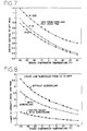
- the absolute value of the improvement in evaporator Capacity may vary for different refrigerant fluids, which improvements are generally quite noticeable and positive, as shown by the graphs in Figures 5 and 9.
- Figure 5 the percentage increase in evaporator capacity as a function of the design evaporator temperature, that is the refrigerant temperature in the evapotator, is illustrated for several commercially available refrigerants.
- the percentage improvement in evaporator capacity is clearly apparent, and consequently the advantage of operating a cooling system, such as refrigerant circuit 12 in Figure 1 is likewise apparent.
- Figure 6 is a P-H (Pressure-Enthalpy) diagram showing the theoretical increase in the work by a compressor as the evaporator temperature decreases, with a relatively constant condensing temperature.
- a constant condensing temperature and with constant subcooling, as noted by the distance 'x', it is noted that as the evaporator temperature is reduced the compressor work increases, which is a common trait for all refrigerants.
- thermal storage system 14 is coupled to a plurality of refrigerant utilizing systems, which are shown as low-temperature apparatus 60, moderate or medium temperature apparatus 70, high-temperature apparatus 80 and "air-conditioning" equipment 90.
- each apparatus has a refrigerant circuit with at least one evaporator, compressor, condenser and expansion device, as well as a heat exchanger or subcooler coupled to its refrigerant circuit.
- Each of the subcoolers of the individual circuits are labelled as subcooler 36, although the particular design, model or type of subcooler is not a limitation to the invention or its operation.
- the structures and operation of each of apparatus 60, 70, 80 and 90 are similar with the exception of their nominated temperature descriptions. Therefore, only low-temperature apparatus 60 will be described in detail, but it is considered that the description also applies to apparatus 70,80, and 90.
- Apparatus 60 in Figure 2 has a refrigerant circuit 100 with at least first evaporator 102, but is shown with second evaporator 104 coupled in parallel , and it is considered that the circuit may have any plurality of evaporators similarly parallel coupled in this refrigerant circuit 100.
- a compressor bank 106 which has at least one compressor, is shown with parallel connected compressors 108,110,112 and 114, which compressor bank 106 is serially coupled downstream to parallel connected evaporator 102 and 104 by common conduit, header or manifold 116 to communicate refrigerant fluid, which is usually low-pressure vapor, to the one or several compressors in bank 106.
- Compressors 108, 110, 112 and 114 compress the refrigerant vapor to a higher pressure and discharge the compressed fluid vapor to second manifold or conduit 118 for communication to condenser 120 through conduit 122.
- refrigerant circuit 100 may have a receiver 124, which is coupled downstream of condenser 120 to receive condensed liquid refrigerant ahead of subcooler 36.
- an optional three-way valve 126 is coupled to subcooler 36 to selectively control refrigerant flow to any of expansion devices, such as a thermal expansion valve (TXV), 32 and subcooler 36.
- TXV thermal expansion valve
- subcooler 36 is connected to conduit 128 upstream of expansion device 32 to communicate refrigerant flow therefrom to expansion device 32 and evaporators 102 and 104.
- the amount of refrigerant flow through optional flow-control valve 126 is used to control the degree of subcooling.
- Subcooler 36 is also coupled to thermal storage system 14 by conduit 130 at discharge outlet 41 with pump 40 interposed in the line to pump media fluid, which may also be a slush-like material mixture of liquid and solid media, to conduit 42 extending through subcooler 36 in a counterflow to refrigerant fluid flow in the illustrated subcooling structure.
- the "amount" of subcooling in this low-temperature apparatus is controllable by the proportion of liquid refrigerant communicated to subcooler 36 by three-way valve 126. In this manner, the amount of subcooled refrigerant to and through subcooler 36 is or may be mixed with a portion of refrigerant directly communicated to conduit 128 for transfer to expansion devices 32 and, evaporators 102 and 104.
- proportional control of refrigerant fluid at a predetermined or calculated temperature is communicated to the refrigerant circuit 100.
- an optional control valve 132 is shown in media return conduit 134 downstream of subcooler 36 and upstream of return port 46, which valve 132 may be operable to either open communication to and through subcooler 36 or open media fluid flow and control the rate of flow of the fluid media through subcooler 36. This latter condition would allow controlling subcooling of refrigerant fluid by subcooler 36.
- Valve 132 may be positioned in a plurality of locations in the media flow circuit to control fluid flow.
- pump 40 may be a variable speed or multispeed pump to control water flow rate through subcooler 36.
- thermal storage system 14 is coupled to an optional full or partial storage coil 156 by conduit 158 with a pump 160 and optional valve 162 therein for communication of media fluid to coil 156.
- pump 160 may be similar to pumps 40 in each of the above-noted refrigeration circuit apparatus.
- Subcooler 36 of air-conditioning apparatus 90 is coupled to inlet conduit 158 ahead of storage coil 156 and downstream of return conduit 164 coupled to thermal storage system 14 for return of media fluid from storage coil 156 to storage system 14.
- Storage coil 156 is an optional arrangement in apparatus 90 to accommodate flow of media fluid directly to cooling coil 156.
- FIG. 3 A further embodiment is shown in Figure 3 with refrigerant circuit 170 coupled to subcooling coil or subcooler 172 in vessel 16 of thermal storage system 14.
- Refrigerant circuit 170 includes evaporator 174, compressor 176 and condenser 178, which are respectively connected in series by conduits 180, 182 and 184.
- Each of evaporator 174, compressor 176, condenser 178 and thermal storage system 14 include inlet and outlet ports for receiving and discharging fluids from these components, as these are common elements known in the art they have not been specifically noted on the figures.
- a receiver 179 downstream of condenser 178 is shown in dashed outline, as it is an optional component that may be utilized in some applications, but is not requisite for illustration of embodiments of the present invention.
- Subcooling coil 172 is positioned in thermal storage vessel 16 and is connected to conduit 184 between condenser 178 in conduit 184 by inlet conduit 188 and return conduit 190 for selective diversion and subcooling of refrigerant fluid of circuit 170.
- a valve arrangement 194 in conduit 184 between condenser 178 and expansion device 192 upstream of evaporator 174 is operable to divert the refrigerant flow either totally or in part through subcooler 172 for heat exchange and temperature reduction of refrigerant fluid in vessel 16.
- Valve arrangement 194 may only include valves 196 and 214, which are shown as solenoid operated valves connected by line 198 and 205, respectively, to signal source 200, which is operable to provide a signal through line 205 to actuate solenoid valve 206 to open or close, to proportionally control flow through conduit 188 and thus to subcooling coil 172.
- Signal source 200 is coupled to a sensor 202 by conduit 204 and may be responsive to a signal from sensor 202 to actuate solenoid valve 196 and 214.
- solenoid valves 196 and 214 can be operable as one three-way valve.
- the sensed signal may be any parameter, as for example time, temperature or a line pressure, the chosen parameter, or parameters, is a design choice.
- valve 206 is shown in conduit 184 and is also coupled to signal apparatus 200 by line 205 to receive a signal in response to a sensed signal, such as that provided by sensor 202, to control flow through conduit 184.
- valve 206 may be a flow control valve to provide proportional subcooling or it may operate to seal conduit 184 to divert all refrigerant condensate through conduit 188 and subcooling coil 172 in vessel 16 for return to conduit 184 downstream of valve 206.
- valve 206 may be operable to be normally open to provide refrigerant flow through conduit 184 only, to thus avoid subcooling coil 172.
- a thermal storage coil or evaporator coil 210 in vessel 16 is coupled between conduits 184 and 160 by conduits 183 and 185, respectively, in parallel with evaporator 174.
- Expansion device 212 is serially arranged downstream of solenoid operated valve 214 and upstream of coil 210.
- solenoid operated valve 214 is coupled to signal source 200 by line 203 for actuation of valve 214 to divert refrigerant fluid through coil 210 and vessel 16 to freeze or chill thermal storage media in vessel 16, generally, but not limited to, periods of minimal or nonuse of evaporator 174.
- valve 196 would allow flow to evaporator 174 during those periods of fluid refrigerant diversion to coil 210, however, it is apparent that valve 196 can be sealed to divert flow to coil 210 during a thermal storage cycle or operation.
- control valve such as solenoid operated valve, slide valve, flow control valve or other valve is not a limitation to the present invention.
- signal source 200 may be any of known types of signal sources, including but not limited to timers, a computer-operable device operable to receive sensed signals and communicate actuation signals in response to these sensed signal, which computer-type operators are known and utilized in control circuits such as home thermostats and automobile control circuits.
- valves 206, 214 and 196 Illustrative of the plurality of operational variants for the plurality of valves in Figure 3 are the modes charted below for valves 206, 214 and 196 in positions or functions, such as open, closed or modulating. A brief description of the resultant positioning or arrangement of the valves for each mode is noted in the last column of this chart.
- the plural apparatus arrangement of Figure 2 is shown in Figure 10 with subcooling coils of each apparatus 60, 70, 80 and 90 provided in thermal storage vessel 16, which obviates the requirement for pumps 40 and the connecting components to Communicate media fluid to subcoolers or subcooling coils 36.
- refrigerant condensate flow from each of refrigerant circuits 60, 70, 80 and 90 is divertable to its associated subcooler coil in vessel 16 by three-way valve 126.
- optional control valves 132 and pumps 40, as well as the associated conduits and signal source connecting lines, which were shown in Figure 2, are not required.
- valves 126 Operation of valves 126 may be accommodated by coupling to a signal source, such as source 48 or 200, by separate lines to actuate the valves and divert or modulate refrigerant fluid flow to subcooling coil 36 in vessel 16 for each of the separate apparatus 60, 70, 80 and 90 to accomplish control subcooling and hence control of apparatus capacity.
- a signal source such as source 48 or 200
- vessel 16 may include a diverter chamber 230 coupled to cavity 18 by conduit 232 with pump 234 therein.
- subcooling coils 36 are located in vessel cavity 18 at a position above the media in cavity 18 at a reference position.
- Media fluid in chamber 230 may be pumped to cavity 18 to elevate the media level in cavity 18 to submorse coils 36, either in whole or in part, and thus provide for subcooling or various degrees of subcooling refrigerant fluid flowing through these coils.
- refrigerant fluid flow may be continuously provided through the coils 36 without the necessity of valves 132 in Figure 2 or valves 126 in Figure 10.
- pump 234 is coupled to and actuable by signal source 200 through line 223 to communicate fluid from chamber 230 to cavity 18.
- Return of fluid media to chamber 230 is accommodated by solenoid operated valve 236 coupled to signal source 200 by line 221 for actuation to return fluid media to chamber 230.
- the "amount" of subcooling may be controlled by the depth of immersion of fluid media coverage of subcooler coils 36 in cavity 18.
- Apparatus 90 may be a full or partial storage system where thermal media is pumped to and from coil 156.
- a subcooling and thermal storage arrangement are shown for equipment which may not be able to incorporate direct expansion apparatus in the thermal storage coil.
- the upper or primary circuit arrangement 300 has compressor bank 106, first and second evaporators 102 and 104, condenser 120, expansion devices 32 and the several noted conduits 118, 122, and 128.
- a heat exchanger 304 such as a shell and tube exchanger, is coupled to refrigerant circuit 300 in parallel with evaporators 102 and 104 and its own control valve/expansion device 308 to open communication of condensate refrigerant from subcooler 36 or condenser 120 and conduit 128 to heat exchanger 304.
- a second conduit loop 310 is coupled between heat exchanger 304 and refrigerant coil 302 and has a second refrigerant fluid, such as a glycol mixture, to be cooled in heat exchanger 304 by the expanding first refrigerant and to chill the media in cavity 18 as the second refrigerant passes through refrigerating coil 302.
- a pump 40 is provided in loop conduit 310 to pump the second refrigerant in loop 310.
- Optional receiver 124 is again provided in primary circuit 300, however, bypass loop 320 with solenoid or proportionally operated valve 322 is coupled around subcooler coil 36 and is operable to communicate condensate fluid to conduit 128 and expansion devices 32 and 308.
- the refrigerant fluid from circuit 300 is operable to provide the thermally stored fluid media in cavity 18. Generally this chilled or frozen media would be provided on the off-peak hours of operation.
- This style or arrangement of components finds particular application with a retrofittable system.
- the pumps and solenoid or proportionally operated valves shown in this structure are couplable to signal sources, such as signal sources 48 and 200 in Figures 1 and 3, for actuation by such apparatus.
- expansion device could feed refrigerant directly into coil 302 for applications supporting direct expansion.
- a fluid cooler, ground source or cooling tower 250 may be serially arranged between apparatus 60, 70, 80 and 90 and thermal storage structure 14 of Figure 2.
- the media fluid is again directed from thermal storage system 14 to subcoolers 36 of each of the noted refrigerant and air-conditioning apparatus.
- the media fluid returning by conduit to thermal storage system 14 is passed through serially arranged fluid cooler or cooling tower 250 to reduce the media temperature ahead of vessel 16 and thus reduce the requisite size of thermal storage vessel 16 and also its capital and operating cost.
- Operation of fluid cooler 250 is known in the art but is illustrated with housing 252, fluid transfer coil 254, spray header 256 and pump 258.
- cooling water in cooler 250 is sprayed on cooling coil 254 with the media coarsing therethrough before its return to either of conduits 130 for direct recycling to subcoolers 36 supplemented by some of fluid media from vessel 16 or for return to cavity of system 14.
- Three-way valve 260 coupled between return port 46, conduit 130 and coil 254 is operable to modulate fluid flow to conduit 130 from both of system 14 and fluid cooler 250.
- Refrigerant circuit 170 coupled to subcooling coil or subcooler 172 in vessel 16 of thermal storage system 14.
- Refrigerant circuit 170 includes evaporator 174, compressor 176, and condenser 178, which are respectively connected in series by conduits 180, 182, and 184,191.
- Expansion device 192 is positioned in conduit 191 upstream of evaporator 174.
- Subcooling coil 172 is positioned in thermal storage vessel 16 and is connected to conduit 184 between condenser 178 and conduit 184 by inlet conduit 188 and return conduit 190 for subcooling of refrigerant fluid from circuit 170.
- valve arrangement 206 placed between conduits 184 and 191 serves to divert some, all, or none of the refrigerant around subcooler 172 for heat exchange and temperature reduction of refrigerant fluid in vessel 16.
- valve 206 is connected by line 205 to signal source 200, which is operable to provide a signal to actuate valve 206 in either an open, closed, or modulating position.
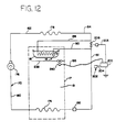
- Housing 17 around refrigerated medium or space 19 encloses thermal storage system 16, refrigerated medium 19, evaporator 174, subcooler coil 172, heat transfer barrier wall 238 and fan or damper 240 in the same refrigerated structure.
- Heat transfer barrier wall 238 is positioned to separate thermal storage system 16 from heat transfer to evaporator coil 174 unless fan or damper 240 is operating.
- Fan or damper 240 is connected by line 195 to signal source 200, which is operable to provide a signal to activate fan or damper 240 in an off, on, or modulating condition to control the time and rate at which thermal storage system 16 will recharge.
- compressor 176 Once compressor 176 is cycled off, refrigerated medium 19 is, or should be, at or below a desired temperature or within another desired operating parameter. Thermal storage system 16 will continue to be charged by providing heat transfer to refrigerated medium 19 from thermal storage system 16 by actuating fan or damper system 240. If there is no appreciable load in medium 19, then compressor 176 will cycle on and off only when the load from charging thermal storage system 16 causes a temperature increase or reaction to conform to the other above-noted operating parameter in medium 19.
- the sensed signal from sensor 202 to signal source 200 may be any parameter as for example, time or temperature or a line pressure, the chosen parameter or parameters is again a design choice.
- the embodiment of Figure 12 can provide reduced refrigerant charge, elimination of evaporator 210 and conduits 185 and 183, elimination of expansion device 212, elimination of solenoid valves 214 and 196, and a simpler control strategy.
- This embodiment may find its greatest application in refrigerators or freezers, which can receive a subcooler coil and thermal storage system inside of the conditioned space.
- the embodiments of Figures 3, 4 and 12 accomplish this goal as the thermal storage charging means of the refrigerant circuit is connected in parallel with the cooling evaporator to provide the requisite in the thermal storage system.
- simultaneous recharging is available when the evaporator load to be cooled is at or below the total cooling system capacity less the load generated during the recharging.
- the embodiments of Figures 3, 4 and 12 are operable to cease, or reduce the rate of, thermal storage recharging without affecting the operation of the cooling refrigerant. circuit.
- a plurality of compressors may be added in parallel with the existing compressors to allow excess compressor capacity to charge the thermal storage system and to serve as a back-up unit for any failed or inoperative compressor.
Landscapes
- Engineering & Computer Science (AREA)
- Physics & Mathematics (AREA)
- Mechanical Engineering (AREA)
- Thermal Sciences (AREA)
- General Engineering & Computer Science (AREA)
- Chemical & Material Sciences (AREA)
- Combustion & Propulsion (AREA)
- Compression-Type Refrigeration Machines With Reversible Cycles (AREA)
- Other Air-Conditioning Systems (AREA)
- Devices That Are Associated With Refrigeration Equipment (AREA)
Applications Claiming Priority (2)
| Application Number | Priority Date | Filing Date | Title |
|---|---|---|---|
| US07/988,547 US5386709A (en) | 1992-12-10 | 1992-12-10 | Subcooling and proportional control of subcooling of liquid refrigerant circuits with thermal storage or low temperature reservoirs |
| US988547 | 1992-12-10 |
Publications (2)
| Publication Number | Publication Date |
|---|---|
| EP0601875A1 true EP0601875A1 (de) | 1994-06-15 |
| EP0601875B1 EP0601875B1 (de) | 1998-03-11 |
Family
ID=25534241
Family Applications (1)
| Application Number | Title | Priority Date | Filing Date |
|---|---|---|---|
| EP93309974A Expired - Lifetime EP0601875B1 (de) | 1992-12-10 | 1993-12-10 | Vorrichtung zur Unterkühlung von Kondensat in Kältekreisläufen |
Country Status (8)
| Country | Link |
|---|---|
| US (1) | US5386709A (de) |
| EP (1) | EP0601875B1 (de) |
| JP (1) | JPH0771829A (de) |
| KR (1) | KR0136075B1 (de) |
| AU (1) | AU665472B2 (de) |
| BR (1) | BR9305022A (de) |
| DE (1) | DE69317368T2 (de) |
| ES (1) | ES2114012T3 (de) |
Cited By (8)
| Publication number | Priority date | Publication date | Assignee | Title |
|---|---|---|---|---|
| FR2737283A1 (fr) * | 1995-07-26 | 1997-01-31 | Mc International | Procede de refrigeration d'un medium, systeme de refrigeration et installation frigorifique |
| EP0763183A4 (de) * | 1994-06-24 | 1998-11-04 | Store Heat & Produce Energy Inc | Heiz-und kühlanordnung mit wärmespeicherung |
| EP0855562A4 (de) * | 1996-08-14 | 2000-04-12 | Daikin Ind Ltd | Klimagerät |
| GB2397871A (en) * | 2003-02-01 | 2004-08-04 | Norfrost Ltd | Chilling device including thermal energy storage means |
| WO2012076028A1 (en) * | 2010-12-08 | 2012-06-14 | Aktiebolaget Electrolux | A cooling unit and method for cooling air |
| US9080796B2 (en) | 2012-08-27 | 2015-07-14 | Ford Global Technologies, Llc | Motor vehicle climate control system |
| EP3839378A1 (de) * | 2019-12-20 | 2021-06-23 | Danfoss A/S | Verfahren zur steuerung eines dampfkompressionssystems während des lastabwurfs |
| CN116907174A (zh) * | 2023-07-12 | 2023-10-20 | 无锡冠亚恒温制冷技术有限公司 | 一种应用于制冷加热系统的流量测量与控制装置及方法 |
Families Citing this family (59)
| Publication number | Priority date | Publication date | Assignee | Title |
|---|---|---|---|---|
| US5826434A (en) * | 1995-11-09 | 1998-10-27 | Novelaire Technologies, L.L.C. | High efficiency outdoor air conditioning system |
| US5791153A (en) * | 1995-11-09 | 1998-08-11 | La Roche Industries Inc. | High efficiency air conditioning system with humidity control |
| US5755104A (en) * | 1995-12-28 | 1998-05-26 | Store Heat And Produce Energy, Inc. | Heating and cooling systems incorporating thermal storage, and defrost cycles for same |
| US6247522B1 (en) | 1998-11-04 | 2001-06-19 | Baltimore Aircoil Company, Inc. | Heat exchange members for thermal storage apparatus |
| DE19907250A1 (de) * | 1999-02-20 | 2000-08-24 | Christian Liebetanz | Kältemaschine |
| US6253573B1 (en) | 1999-03-10 | 2001-07-03 | Specialty Equipment Companies, Inc. | High efficiency refrigeration system |
| US6148634A (en) * | 1999-04-26 | 2000-11-21 | 3M Innovative Properties Company | Multistage rapid product refrigeration apparatus and method |
| US6170272B1 (en) | 1999-04-29 | 2001-01-09 | Systematic Refrigeration, Inc. | Refrigeration system with inertial subcooling |
| JP2003500034A (ja) * | 1999-05-20 | 2003-01-07 | スペシャルティ イクィップメント コンパニーズ,インコーポレイテッド | 半冷凍、冷凍食品ディスペンシング機械の改良されたビータ/ダッシャ |
| US6471694B1 (en) | 2000-08-09 | 2002-10-29 | Cryogen, Inc. | Control system for cryosurgery |
| US7004936B2 (en) * | 2000-08-09 | 2006-02-28 | Cryocor, Inc. | Refrigeration source for a cryoablation catheter |
| US6460355B1 (en) * | 1999-08-31 | 2002-10-08 | Guy T. Trieskey | Environmental test chamber fast cool down and heat up system |
| US6161391A (en) * | 1999-08-31 | 2000-12-19 | Trieskey; Guy T. | Environmental test chamber fast cool down system and method therefor |
| US6668567B2 (en) * | 1999-09-17 | 2003-12-30 | Robert Levenduski | Thermal storage apparatus and method for air conditioning system |
| DE10019580B4 (de) * | 2000-04-20 | 2010-06-10 | Behr Gmbh & Co. Kg | Einrichtung zum Kühlen eines Innenraumes eines Kraftfahrzeugs |
| CN1122155C (zh) * | 2000-08-18 | 2003-09-24 | 徐生恒 | 井式液体冷热源系统 |
| US7127901B2 (en) * | 2001-07-20 | 2006-10-31 | Brooks Automation, Inc. | Helium management control system |
| US7065979B2 (en) * | 2002-10-30 | 2006-06-27 | Delaware Capital Formation, Inc. | Refrigeration system |
| US8491636B2 (en) | 2004-03-23 | 2013-07-23 | Medtronic Cryopath LP | Method and apparatus for inflating and deflating balloon catheters |
| US7727228B2 (en) | 2004-03-23 | 2010-06-01 | Medtronic Cryocath Lp | Method and apparatus for inflating and deflating balloon catheters |
| JP5099503B2 (ja) | 2004-07-22 | 2012-12-19 | イーアールエイ (エンビロンメンタル リフリジェレイション オルターナティブズ) ピーティーワイ エルティーディー | 冷却装置 |
| SE527882C2 (sv) * | 2004-11-26 | 2006-07-04 | Foersta Naervaermeverket Ab | Värmeanläggning och uppvärmningsförfarande |
| US7243909B2 (en) * | 2004-12-10 | 2007-07-17 | Koplin Edward C | Collector sump cooling tower |
| KR100657461B1 (ko) * | 2004-12-28 | 2006-12-14 | 엘지전자 주식회사 | 가습 기능을 갖는 냉난방 공기 조화기 |
| US8206345B2 (en) | 2005-03-07 | 2012-06-26 | Medtronic Cryocath Lp | Fluid control system for a medical device |
| US7726151B2 (en) | 2005-04-05 | 2010-06-01 | Tecumseh Products Company | Variable cooling load refrigeration cycle |
| CN1952531B (zh) | 2005-10-17 | 2010-05-12 | 乐金电子(天津)电器有限公司 | 中央空调的过冷却装置 |
| CN102203530A (zh) * | 2008-02-20 | 2011-09-28 | 国际壳牌研究有限公司 | 用于冷却和分离烃流的方法和设备 |
| US8631666B2 (en) * | 2008-08-07 | 2014-01-21 | Hill Phoenix, Inc. | Modular CO2 refrigeration system |
| US8166773B2 (en) * | 2008-10-08 | 2012-05-01 | Venturedyne, Ltd. | Refrigeration capacity banking for thermal cycling |
| US8511109B2 (en) * | 2009-07-15 | 2013-08-20 | Whirlpool Corporation | High efficiency refrigerator |
| ES2363288B1 (es) * | 2010-01-15 | 2012-02-27 | Abengoa Solar New Technologies S.A. | Receptor solar de sales fundidas y procedimiento para reducir el gradiente térmico en dicho receptor. |
| US9541311B2 (en) | 2010-11-17 | 2017-01-10 | Hill Phoenix, Inc. | Cascade refrigeration system with modular ammonia chiller units |
| US9657977B2 (en) | 2010-11-17 | 2017-05-23 | Hill Phoenix, Inc. | Cascade refrigeration system with modular ammonia chiller units |
| US9664424B2 (en) | 2010-11-17 | 2017-05-30 | Hill Phoenix, Inc. | Cascade refrigeration system with modular ammonia chiller units |
| WO2012080771A1 (en) * | 2010-12-17 | 2012-06-21 | Renault Trucks | Truck with a refrigerated compartment |
| DE102011053256A1 (de) * | 2011-09-05 | 2013-03-07 | Dr. Ing. H.C. F. Porsche Aktiengesellschaft | Kältekreislauf zum Einsatz in einem Kraftfahrzeug |
| WO2013159827A1 (en) * | 2012-04-27 | 2013-10-31 | Carrier Corporation | Cooling system |
| US8997507B2 (en) * | 2012-10-22 | 2015-04-07 | Whirlpool Corporation | Low energy evaporator defrost |
| US9733005B2 (en) | 2013-03-15 | 2017-08-15 | Johnson Controls Technology Company | Subcooling system with thermal storage |
| RU2592883C2 (ru) | 2013-08-30 | 2016-07-27 | Общество С Ограниченной Ответственностью "Яндекс" | Система охлаждения, способ эксплуатации такой системы и резервное устройство охлаждения |
| US10047985B2 (en) * | 2014-03-10 | 2018-08-14 | Johnson Controls Technology Company | Subcooling system with thermal energy storage |
| US10101060B2 (en) | 2014-07-31 | 2018-10-16 | Carrier Corporation | Cooling system |
| CN107110587A (zh) | 2014-09-19 | 2017-08-29 | 艾斯姆士尔机有限公司 | 实现配置为利用热能储存为目标空间保持低温的鲁棒空调系统的系统和方法 |
| JP6566860B2 (ja) * | 2014-12-22 | 2019-08-28 | 日本碍子株式会社 | ケミカルヒートポンプ |
| JP2016125730A (ja) * | 2014-12-26 | 2016-07-11 | ダイキン工業株式会社 | 蓄熱式空気調和機 |
| US10072896B2 (en) | 2016-04-22 | 2018-09-11 | LoCap Energy, LLC | Modular thermal energy storage system |
| US10502468B2 (en) | 2016-10-05 | 2019-12-10 | Johnson Controls Technology Company | Parallel capillary expansion tube systems and methods |
| US11512880B2 (en) * | 2016-11-22 | 2022-11-29 | Mitsubishi Electric Corporation | Refrigeration cycle device |
| CN106969444B (zh) * | 2017-03-06 | 2019-12-10 | 深圳达实智能股份有限公司 | 一种多机组串联的水蓄能系统及其使用方法 |
| US11143468B2 (en) | 2017-04-03 | 2021-10-12 | Heatcraft Refrigeration Products Llc | Pulsing adiabatic gas cooler |
| US10782054B2 (en) | 2018-02-22 | 2020-09-22 | Rolls-Royce North American Technologies Inc. | Cooling recharge system |
| US10718255B2 (en) * | 2018-02-22 | 2020-07-21 | Rolls-Royce North American Technologies Inc. | Cooling flow control system |
| US20190316818A1 (en) * | 2018-04-12 | 2019-10-17 | Rolls-Royce Corporation | Thermal energy storage and heat rejection system |
| WO2020123963A1 (en) | 2018-12-13 | 2020-06-18 | Baltimore Aircoil Company, Inc. | Fan array fault response control system |
| US11732967B2 (en) | 2019-12-11 | 2023-08-22 | Baltimore Aircoil Company, Inc. | Heat exchanger system with machine-learning based optimization |
| FR3122246B1 (fr) * | 2021-04-27 | 2023-06-30 | Arkeon Energy | Pompe à chaleur et dispositif de stockage d’énergie à changement de phase |
| GB2635978A (en) | 2022-06-24 | 2025-06-04 | Baltimore Aircoil Co Inc | Heat transfer apparatus and method |
| US20240253426A1 (en) * | 2023-01-27 | 2024-08-01 | Ford Global Technologies, Llc | Dehumidification control strategy |
Citations (4)
| Publication number | Priority date | Publication date | Assignee | Title |
|---|---|---|---|---|
| GB230586A (en) * | 1924-01-16 | 1925-03-19 | William George Brettell | Improvements in and connected with refrigeration systems in which gases are liquefied by compression and the liquid evaporated |
| US2515825A (en) * | 1945-03-16 | 1950-07-18 | Carrier Corp | Single stage refrigeration utilizing holdover means |
| DE823143C (de) * | 1949-08-18 | 1951-11-29 | Linde Eismasch Ag | Verhuetung des Entstehens groesserer Dampfmengen hinter dem Schwimmerregler von Kaelteanlagen |
| EP0402131A2 (de) * | 1989-06-07 | 1990-12-12 | Baltimore Aircoil Company, Inc. | Kühlanlage mit Zusatzwärmespeicher |
Family Cites Families (22)
| Publication number | Priority date | Publication date | Assignee | Title |
|---|---|---|---|---|
| US1523112A (en) * | 1924-05-31 | 1925-01-13 | Frank Kanter | Refrigerating apparatus |
| US1782651A (en) * | 1927-03-07 | 1930-11-25 | Baker Ice Machine Co Inc | Refrigerating system |
| US2120185A (en) * | 1934-10-03 | 1938-06-07 | Nash Kelvinator Corp | Refrigerating apparatus |
| US2460623A (en) * | 1944-10-24 | 1949-02-01 | Reconstruction Finance Corp | Liquid cooler for air-conditioning systems |
| US2712732A (en) * | 1954-09-09 | 1955-07-12 | Gen Electric | Refrigerating apparatus |
| US4302944A (en) * | 1980-07-15 | 1981-12-01 | Westinghouse Electric Corp. | Thermal storage method and apparatus |
| US4373346A (en) * | 1981-03-25 | 1983-02-15 | Hebert Thomas H | Precool/subcool system and condenser therefor |
| US4493193A (en) * | 1982-03-05 | 1985-01-15 | Rutherford C. Lake, Jr. | Reversible cycle heating and cooling system |
| US4409796A (en) * | 1982-03-05 | 1983-10-18 | Rutherford C. Lake, Jr. | Reversible cycle heating and cooling system |
| US4553401A (en) * | 1982-03-05 | 1985-11-19 | Fisher Ralph H | Reversible cycle heating and cooling system |
| US4637219A (en) * | 1986-04-23 | 1987-01-20 | Enron Corp. | Peak shaving system for air conditioning |
| US4720984A (en) * | 1986-05-23 | 1988-01-26 | Transphase Systems, Inc. | Apparatus for storing cooling capacity |
| JPS646650A (en) * | 1987-06-26 | 1989-01-11 | Yamato Setsubi Koji Kk | Refrigerating method |
| JPS6410062A (en) * | 1987-06-30 | 1989-01-13 | Daikin Ind Ltd | Heat accumulation type air conditioner |
| JP2508240B2 (ja) * | 1989-02-22 | 1996-06-19 | ダイキン工業株式会社 | 氷蓄熱装置および該氷蓄熱装置を備えた氷蓄熱式空気調和装置 |
| JPH07109324B2 (ja) * | 1989-03-24 | 1995-11-22 | ダイキン工業株式会社 | 蓄熱式空気調和装置 |
| US5038574A (en) * | 1989-05-12 | 1991-08-13 | Baltimore Aircoil Company, Inc. | Combined mechanical refrigeration and absorption refrigeration method and apparatus |
| US4966007A (en) * | 1989-05-12 | 1990-10-30 | Baltimore Aircoil Company, Inc. | Absorption refrigeration method and apparatus |
| US4964279A (en) * | 1989-06-07 | 1990-10-23 | Baltimore Aircoil Company | Cooling system with supplemental thermal storage |
| US5183100A (en) * | 1991-02-14 | 1993-02-02 | Harrell Jr James E | System for efficiently exchanging heat or cooling ground water in a deep well |
| JP2646877B2 (ja) * | 1991-03-29 | 1997-08-27 | 三菱電機株式会社 | 蓄熱式冷凍サイクル装置 |
| US5150581A (en) * | 1991-06-24 | 1992-09-29 | Baltimore Aircoil Company | Head pressure controller for air conditioning and refrigeration systems |
-
1992
- 1992-12-10 US US07/988,547 patent/US5386709A/en not_active Expired - Fee Related
-
1993
- 1993-12-10 DE DE69317368T patent/DE69317368T2/de not_active Expired - Fee Related
- 1993-12-10 KR KR1019930027460A patent/KR0136075B1/ko not_active Expired - Fee Related
- 1993-12-10 EP EP93309974A patent/EP0601875B1/de not_active Expired - Lifetime
- 1993-12-10 AU AU52319/93A patent/AU665472B2/en not_active Ceased
- 1993-12-10 BR BR9305022A patent/BR9305022A/pt not_active IP Right Cessation
- 1993-12-10 ES ES93309974T patent/ES2114012T3/es not_active Expired - Lifetime
- 1993-12-10 JP JP5345747A patent/JPH0771829A/ja active Pending
Patent Citations (4)
| Publication number | Priority date | Publication date | Assignee | Title |
|---|---|---|---|---|
| GB230586A (en) * | 1924-01-16 | 1925-03-19 | William George Brettell | Improvements in and connected with refrigeration systems in which gases are liquefied by compression and the liquid evaporated |
| US2515825A (en) * | 1945-03-16 | 1950-07-18 | Carrier Corp | Single stage refrigeration utilizing holdover means |
| DE823143C (de) * | 1949-08-18 | 1951-11-29 | Linde Eismasch Ag | Verhuetung des Entstehens groesserer Dampfmengen hinter dem Schwimmerregler von Kaelteanlagen |
| EP0402131A2 (de) * | 1989-06-07 | 1990-12-12 | Baltimore Aircoil Company, Inc. | Kühlanlage mit Zusatzwärmespeicher |
Cited By (10)
| Publication number | Priority date | Publication date | Assignee | Title |
|---|---|---|---|---|
| EP0763183A4 (de) * | 1994-06-24 | 1998-11-04 | Store Heat & Produce Energy Inc | Heiz-und kühlanordnung mit wärmespeicherung |
| FR2737283A1 (fr) * | 1995-07-26 | 1997-01-31 | Mc International | Procede de refrigeration d'un medium, systeme de refrigeration et installation frigorifique |
| EP0855562A4 (de) * | 1996-08-14 | 2000-04-12 | Daikin Ind Ltd | Klimagerät |
| US6164086A (en) * | 1996-08-14 | 2000-12-26 | Daikin Industries, Ltd. | Air conditioner |
| GB2397871A (en) * | 2003-02-01 | 2004-08-04 | Norfrost Ltd | Chilling device including thermal energy storage means |
| WO2012076028A1 (en) * | 2010-12-08 | 2012-06-14 | Aktiebolaget Electrolux | A cooling unit and method for cooling air |
| US9080796B2 (en) | 2012-08-27 | 2015-07-14 | Ford Global Technologies, Llc | Motor vehicle climate control system |
| EP3839378A1 (de) * | 2019-12-20 | 2021-06-23 | Danfoss A/S | Verfahren zur steuerung eines dampfkompressionssystems während des lastabwurfs |
| WO2021122444A1 (en) * | 2019-12-20 | 2021-06-24 | Danfoss A/S | A method for controlling a vapour compression system during load shedding |
| CN116907174A (zh) * | 2023-07-12 | 2023-10-20 | 无锡冠亚恒温制冷技术有限公司 | 一种应用于制冷加热系统的流量测量与控制装置及方法 |
Also Published As
| Publication number | Publication date |
|---|---|
| EP0601875B1 (de) | 1998-03-11 |
| BR9305022A (pt) | 1994-06-21 |
| DE69317368D1 (de) | 1998-04-16 |
| DE69317368T2 (de) | 1998-07-02 |
| KR0136075B1 (ko) | 1998-07-01 |
| US5386709A (en) | 1995-02-07 |
| JPH0771829A (ja) | 1995-03-17 |
| AU5231993A (en) | 1994-06-23 |
| AU665472B2 (en) | 1996-01-04 |
| ES2114012T3 (es) | 1998-05-16 |
| KR940015450A (ko) | 1994-07-21 |
Similar Documents
| Publication | Publication Date | Title |
|---|---|---|
| US5386709A (en) | Subcooling and proportional control of subcooling of liquid refrigerant circuits with thermal storage or low temperature reservoirs | |
| EP0602911B1 (de) | Kühlanlage | |
| US5894739A (en) | Compound refrigeration system for water chilling and thermal storage | |
| US8707723B2 (en) | Multiple refrigerant thermal energy storage and cooling system with secondary refrigerant isolation | |
| US5755104A (en) | Heating and cooling systems incorporating thermal storage, and defrost cycles for same | |
| AU719697B2 (en) | Thermal energy storage air conditioning system | |
| US5211029A (en) | Combined multi-modal air conditioning apparatus and negative energy storage system | |
| US8181470B2 (en) | Thermal energy storage and cooling system utilizing multiple refrigerant and cooling loops with a common evaporator coil | |
| US5372011A (en) | Air conditioning and heat pump system utilizing thermal storage | |
| US5673567A (en) | Refrigeration system with heat reclaim and method of operation | |
| US5157943A (en) | Refrigeration system including capillary tube/suction line heat transfer | |
| EP1794516B1 (de) | System mit sekundärkältemittelisolation zum speichern und kühlen von wärmeenergie | |
| EP0485147A1 (de) | Kühlsystem | |
| JP3499171B2 (ja) | 蓄熱式冷却装置 | |
| EP1616136B1 (de) | Kühlsystem und verfahren zum betrieb eines solchen systems | |
| CN114593535B (zh) | 多温区制冷与制热集成系统及其控制方法 | |
| CA2163076C (en) | Refrigeration system with heat reclaim and method of operation | |
| JP2002295868A (ja) | 氷蓄熱式冷却システム | |
| WO1994009328A1 (en) | Thermal storage control arrangements | |
| JPH11230659A (ja) | 氷蓄熱システム |
Legal Events
| Date | Code | Title | Description |
|---|---|---|---|
| PUAI | Public reference made under article 153(3) epc to a published international application that has entered the european phase |
Free format text: ORIGINAL CODE: 0009012 |
|
| AK | Designated contracting states |
Kind code of ref document: A1 Designated state(s): BE CH DE ES FR IT LI NL |
|
| 17P | Request for examination filed |
Effective date: 19940801 |
|
| 17Q | First examination report despatched |
Effective date: 19951023 |
|
| GRAG | Despatch of communication of intention to grant |
Free format text: ORIGINAL CODE: EPIDOS AGRA |
|
| GRAG | Despatch of communication of intention to grant |
Free format text: ORIGINAL CODE: EPIDOS AGRA |
|
| GRAH | Despatch of communication of intention to grant a patent |
Free format text: ORIGINAL CODE: EPIDOS IGRA |
|
| GRAH | Despatch of communication of intention to grant a patent |
Free format text: ORIGINAL CODE: EPIDOS IGRA |
|
| ITF | It: translation for a ep patent filed | ||
| GRAA | (expected) grant |
Free format text: ORIGINAL CODE: 0009210 |
|
| AK | Designated contracting states |
Kind code of ref document: B1 Designated state(s): BE CH DE ES FR IT LI NL |
|
| REG | Reference to a national code |
Ref country code: CH Ref legal event code: NV Representative=s name: A. BRAUN, BRAUN, HERITIER, ESCHMANN AG PATENTANWAE Ref country code: CH Ref legal event code: EP |
|
| REF | Corresponds to: |
Ref document number: 69317368 Country of ref document: DE Date of ref document: 19980416 |
|
| REG | Reference to a national code |
Ref country code: ES Ref legal event code: FG2A Ref document number: 2114012 Country of ref document: ES Kind code of ref document: T3 |
|
| ET | Fr: translation filed | ||
| PLBE | No opposition filed within time limit |
Free format text: ORIGINAL CODE: 0009261 |
|
| STAA | Information on the status of an ep patent application or granted ep patent |
Free format text: STATUS: NO OPPOSITION FILED WITHIN TIME LIMIT |
|
| 26N | No opposition filed | ||
| PGFP | Annual fee paid to national office [announced via postgrant information from national office to epo] |
Ref country code: FR Payment date: 19991117 Year of fee payment: 7 |
|
| PGFP | Annual fee paid to national office [announced via postgrant information from national office to epo] |
Ref country code: DE Payment date: 19991118 Year of fee payment: 7 |
|
| PGFP | Annual fee paid to national office [announced via postgrant information from national office to epo] |
Ref country code: NL Payment date: 19991122 Year of fee payment: 7 Ref country code: CH Payment date: 19991122 Year of fee payment: 7 |
|
| PGFP | Annual fee paid to national office [announced via postgrant information from national office to epo] |
Ref country code: ES Payment date: 19991214 Year of fee payment: 7 |
|
| PGFP | Annual fee paid to national office [announced via postgrant information from national office to epo] |
Ref country code: BE Payment date: 19991215 Year of fee payment: 7 |
|
| PG25 | Lapsed in a contracting state [announced via postgrant information from national office to epo] |
Ref country code: LI Free format text: LAPSE BECAUSE OF NON-PAYMENT OF DUE FEES Effective date: 20001231 Ref country code: CH Free format text: LAPSE BECAUSE OF NON-PAYMENT OF DUE FEES Effective date: 20001231 Ref country code: BE Free format text: LAPSE BECAUSE OF NON-PAYMENT OF DUE FEES Effective date: 20001231 |
|
| BERE | Be: lapsed |
Owner name: BALTIMORE AIRCOIL CY INC. Effective date: 20001231 |
|
| PG25 | Lapsed in a contracting state [announced via postgrant information from national office to epo] |
Ref country code: NL Free format text: LAPSE BECAUSE OF NON-PAYMENT OF DUE FEES Effective date: 20010701 |
|
| REG | Reference to a national code |
Ref country code: CH Ref legal event code: PL |
|
| PG25 | Lapsed in a contracting state [announced via postgrant information from national office to epo] |
Ref country code: FR Free format text: LAPSE BECAUSE OF NON-PAYMENT OF DUE FEES Effective date: 20010831 |
|
| NLV4 | Nl: lapsed or anulled due to non-payment of the annual fee |
Effective date: 20010701 |
|
| REG | Reference to a national code |
Ref country code: FR Ref legal event code: ST |
|
| PG25 | Lapsed in a contracting state [announced via postgrant information from national office to epo] |
Ref country code: DE Free format text: LAPSE BECAUSE OF NON-PAYMENT OF DUE FEES Effective date: 20011002 |
|
| PG25 | Lapsed in a contracting state [announced via postgrant information from national office to epo] |
Ref country code: ES Free format text: LAPSE BECAUSE OF NON-PAYMENT OF DUE FEES Effective date: 20011211 |
|
| REG | Reference to a national code |
Ref country code: ES Ref legal event code: FD2A Effective date: 20020112 |
|
| PG25 | Lapsed in a contracting state [announced via postgrant information from national office to epo] |
Ref country code: IT Free format text: LAPSE BECAUSE OF NON-PAYMENT OF DUE FEES;WARNING: LAPSES OF ITALIAN PATENTS WITH EFFECTIVE DATE BEFORE 2007 MAY HAVE OCCURRED AT ANY TIME BEFORE 2007. THE CORRECT EFFECTIVE DATE MAY BE DIFFERENT FROM THE ONE RECORDED. Effective date: 20051210 |