EP0601975A1 - Boulon d'ancrage - Google Patents
Boulon d'ancrage Download PDFInfo
- Publication number
- EP0601975A1 EP0601975A1 EP93810826A EP93810826A EP0601975A1 EP 0601975 A1 EP0601975 A1 EP 0601975A1 EP 93810826 A EP93810826 A EP 93810826A EP 93810826 A EP93810826 A EP 93810826A EP 0601975 A1 EP0601975 A1 EP 0601975A1
- Authority
- EP
- European Patent Office
- Prior art keywords
- bolt
- anchor bolt
- anchor
- bolt element
- expansion
- Prior art date
- Legal status (The legal status is an assumption and is not a legal conclusion. Google has not performed a legal analysis and makes no representation as to the accuracy of the status listed.)
- Granted
Links
- 238000005452 bending Methods 0.000 claims description 10
- 229910000831 Steel Inorganic materials 0.000 claims description 3
- 239000010959 steel Substances 0.000 claims description 3
- 230000037431 insertion Effects 0.000 claims 1
- 238000003780 insertion Methods 0.000 claims 1
- 241001295925 Gegenes Species 0.000 description 6
- 239000004566 building material Substances 0.000 description 3
- 239000002184 metal Substances 0.000 description 2
- 238000004080 punching Methods 0.000 description 2
- 239000004035 construction material Substances 0.000 description 1
- 230000001419 dependent effect Effects 0.000 description 1
- 238000004519 manufacturing process Methods 0.000 description 1
- 230000002093 peripheral effect Effects 0.000 description 1
- 230000002028 premature Effects 0.000 description 1
Images


Classifications
-
- F—MECHANICAL ENGINEERING; LIGHTING; HEATING; WEAPONS; BLASTING
- F16—ENGINEERING ELEMENTS AND UNITS; GENERAL MEASURES FOR PRODUCING AND MAINTAINING EFFECTIVE FUNCTIONING OF MACHINES OR INSTALLATIONS; THERMAL INSULATION IN GENERAL
- F16B—DEVICES FOR FASTENING OR SECURING CONSTRUCTIONAL ELEMENTS OR MACHINE PARTS TOGETHER, e.g. NAILS, BOLTS, CIRCLIPS, CLAMPS, CLIPS OR WEDGES; JOINTS OR JOINTING
- F16B13/00—Dowels or other devices fastened in walls or the like by inserting them in holes made therein for that purpose
- F16B13/04—Dowels or other devices fastened in walls or the like by inserting them in holes made therein for that purpose with parts gripping in the hole or behind the reverse side of the wall after inserting from the front
- F16B13/06—Dowels or other devices fastened in walls or the like by inserting them in holes made therein for that purpose with parts gripping in the hole or behind the reverse side of the wall after inserting from the front combined with expanding sleeve
- F16B13/063—Dowels or other devices fastened in walls or the like by inserting them in holes made therein for that purpose with parts gripping in the hole or behind the reverse side of the wall after inserting from the front combined with expanding sleeve by the use of an expander
Definitions
- the invention relates to an anchor bolt with at least two bolt elements, of which at least one in the front region of the anchor bolt with at least one inclined surface is in spreading contact with the other bolt element, which extends outwards in the direction of the front anchor bolt end, at least one of these bolt elements being one for positive locking Connection with an object to be fastened has a specific fastening area.
- Anchor bolts of this type are known from US-A-2 362 969, Fr-A-2 335 721, GB-A-1 534 298 and DE-B-2 829 158.
- these known anchor bolts are spread apart by driving in one of the elongated bolt elements after the other bolt element has been inserted into the wall receiving hole.
- expansion anchors are often used for attaching objects to a ceiling.
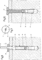
- the longest expansion leg 12 When the outer bolt element 5 is driven in, starting from the arrangement according to FIG. 1, the longest expansion leg 12 first comes into contact with the more bevelled peripheral region 13 of the cone 3, so that the front end of the inner bolt element 2, which is from the outer bolt element 5 is included, a bending force is exerted.
- the shorter spreading legs 10 and 11 which are obliquely opposite the longest spreading leg 12, are expanded and absorb a smaller force which counteracts the bending force mentioned, so that bending tension remains at the end of the inner bolt element.
- This bending stress prevents the expansion engagement of the anchor bolt 1 from loosening when the borehole 8 widens as a result of bending stresses or cracks in the construction material 14 surrounding the borehole 8.
- the asymmetrical spreading forces acting on the front area of the anchor bolt 1 also result in an improved engagement of the anchor bolt 1 in the building material 14.
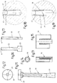
- FIGS. 18 and 19 show that an anchor bolt 1 ′′ according to the invention can also be designed with equally long expansion legs 15, 16 of the surrounding bolt element 5 ′′.
- the asymmetrical design that causes a bending stress in the expansion area is achieved solely by an asymmetrically designed cone 3 ′′. Since the cone is centered between the expansion legs 15, 16 in the tensioned state, it is deformed elastically in bending. This illustrates a comparison between the representations of FIGS. 18 and 19.
- the exemplary embodiment of the invention according to FIGS. 8 to 17 differs from that according to FIGS. 1 to 7 in that the enclosing bolt element 18 extends only over less than half the length of the enclosed bolt element 19 or only in the expansion region of the anchor bolt 20.
- Driving this short bolt element 18 to Spreading over the cone 21 takes place by means of an additional drive-in shaft 22, the wider, front end 23 of which lies against the rear end of the sleeve-shaped, outer bolt element 18.
- the pin element 19 having the cone 21 for the drive-in shaft 22 has a guide channel which is open on both sides and which begins with an opening 25 in the flange 26 of the pin element 19 which is adapted to the cross-sectional shape of the drive-in shaft 22.
- the driving shank can be inserted laterally into the guide channel 24.
- the driving shaft 22 assumes the position shown in FIG.
- the outer bolt element 18 is then, starting from the sheet metal blank according to FIG. 15, bent around the bolt element 19.
- two or more bolt elements can also be arranged next to one another, provided that they can be spread out against one another via inclined surfaces are. If two outer bolt elements enclose an inner one between them, they are preferably connected to one another, so that the alignment with one another required for spreading does not have to take place only when inserted into the borehole.
- the fastening extension can also extend in a hook shape on only one side.
- a fastening area can also be provided on each of the bolt elements, as is known per se from US-A-2362969.
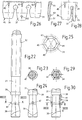
- the fastening area on the first, inner, elongated bolt element 31 consists of a screw thread 32, onto which a screw nut 33 is screwed.
- the second, outer bolt element 34 extends like a cuff like only over a short part of the elongated bolt element 31. It lies with its three legs 35, 36, 37 of different length on the one hand on the asymmetrical expansion cone 38 and is supported on the other hand on a circumferential shoulder 39 of the inner bolt element 31, through which it is inserted the anchor bolt 30 in a borehole 8 maintains its position at the front end of the anchor bolt 30.
- connection between the inner, threaded shaft-shaped bolt element 31 and the outer bolt element 34 takes place in that the latter is bent around the front end of the inner bolt element 31 starting from the punched and embossed sheet metal piece 45 according to FIG. 26, so that it is in the form of a continuous longitudinal slot 46 having sleeve takes.
- a nose 47 formed in the front area of the inner pin 31 engages in the longitudinal slot 46 of this pin element 34.
- the inner bolt element 55 which is formed from a flat steel, has a T-shaped widened shape Head 57, which extends transversely through two slots 58, 59 of the outer bolt element 51, which form opposite one another and form the expansion legs 52, 53, and which rests on a retaining ring 60 which surrounds both bolt elements 51 and 55.
- the outer bolt element 51 Before inserting the anchor bolt 50 into the borehole 8 and in the untensioned starting position according to FIG. 31, the outer bolt element is held by small elevations 61 on the retaining ring 60, so that its premature spreading on the expansion body 54 is prevented.
- this holder When the outer bolt element 51 is driven in by hammer blows on its small elevations 62 at the rear end 63, this holder is overcome at the elevations 61, and the ends of the expansion limbs 52, 53 slide over the wedge-shaped expansion body 54 of the inner bolt element 55 and expand into the one shown in FIG. 32 shown position to the outside.
- the rear end 63 of the outer bolt element 51 widens. This expansion is supported by the contact with the enclosed, wedge-shaped upward tapering head 57 of the inner bolt element 55.
- the resulting mushroom-like widening 64 of the outer bolt element 51, together with the head 57 of the inner bolt element 55, overlapping the retaining ring 60, causes one secure fastening of the wall plate 56 by the retaining
- This anchor bolt 50 according to FIGS. 31 to 42 can also be produced particularly easily by punching out and bending deformed sheet steel parts. After punching out, the wedge-shaped expansion body 54 is brought into a position opposite the expansion legs 52, 53 of the outer bolt element 51 by means of a torsional deformation of 90 ° relative to the head 57 with its wedge surfaces 66, 67.
Landscapes
- Engineering & Computer Science (AREA)
- General Engineering & Computer Science (AREA)
- Mechanical Engineering (AREA)
- Joining Of Building Structures In Genera (AREA)
- Dowels (AREA)
Applications Claiming Priority (4)
| Application Number | Priority Date | Filing Date | Title |
|---|---|---|---|
| CH374492A CH688061A5 (de) | 1992-12-07 | 1992-12-07 | Ankerbolzen. |
| CH3744/92 | 1992-12-07 | ||
| CH2450/93 | 1993-08-17 | ||
| CH245093A CH688724A5 (de) | 1993-08-17 | 1993-08-17 | Ankerbolzen. |
Publications (2)
| Publication Number | Publication Date |
|---|---|
| EP0601975A1 true EP0601975A1 (fr) | 1994-06-15 |
| EP0601975B1 EP0601975B1 (fr) | 1999-06-02 |
Family
ID=25690479
Family Applications (1)
| Application Number | Title | Priority Date | Filing Date |
|---|---|---|---|
| EP93810826A Expired - Lifetime EP0601975B1 (fr) | 1992-12-07 | 1993-11-25 | Boulon d'ancrage |
Country Status (4)
| Country | Link |
|---|---|
| EP (1) | EP0601975B1 (fr) |
| AT (1) | ATE180874T1 (fr) |
| DE (1) | DE59309626D1 (fr) |
| DK (1) | DK0601975T3 (fr) |
Families Citing this family (1)
| Publication number | Priority date | Publication date | Assignee | Title |
|---|---|---|---|---|
| DE102020103577A1 (de) | 2020-02-12 | 2021-08-12 | Paul Zinßer | Demontierbarer Bolzenanker und Verfahren zu seiner Demontage |
Citations (5)
| Publication number | Priority date | Publication date | Assignee | Title |
|---|---|---|---|---|
| US3178990A (en) * | 1961-11-13 | 1965-04-20 | Porter Co Inc H K | Expansion unit with initial expansion means |
| DE2810324A1 (de) * | 1978-03-10 | 1979-09-20 | Faester Gmbh & Co Kg | Duebel |
| EP0019782A2 (fr) * | 1979-05-31 | 1980-12-10 | Albert Berner GmbH & Co KG | Cheville métallique creuse |
| US4557631A (en) * | 1983-08-29 | 1985-12-10 | Donan Jr David C | Off-center rock bolt anchor and method |
| DE3809403A1 (de) * | 1988-03-21 | 1989-10-12 | Silvia Zondler | Deckenduebel |
-
1993
- 1993-11-25 DK DK93810826T patent/DK0601975T3/da active
- 1993-11-25 EP EP93810826A patent/EP0601975B1/fr not_active Expired - Lifetime
- 1993-11-25 AT AT93810826T patent/ATE180874T1/de not_active IP Right Cessation
- 1993-11-25 DE DE59309626T patent/DE59309626D1/de not_active Expired - Fee Related
Patent Citations (5)
| Publication number | Priority date | Publication date | Assignee | Title |
|---|---|---|---|---|
| US3178990A (en) * | 1961-11-13 | 1965-04-20 | Porter Co Inc H K | Expansion unit with initial expansion means |
| DE2810324A1 (de) * | 1978-03-10 | 1979-09-20 | Faester Gmbh & Co Kg | Duebel |
| EP0019782A2 (fr) * | 1979-05-31 | 1980-12-10 | Albert Berner GmbH & Co KG | Cheville métallique creuse |
| US4557631A (en) * | 1983-08-29 | 1985-12-10 | Donan Jr David C | Off-center rock bolt anchor and method |
| DE3809403A1 (de) * | 1988-03-21 | 1989-10-12 | Silvia Zondler | Deckenduebel |
Also Published As
| Publication number | Publication date |
|---|---|
| EP0601975B1 (fr) | 1999-06-02 |
| ATE180874T1 (de) | 1999-06-15 |
| DE59309626D1 (de) | 1999-07-08 |
| DK0601975T3 (da) | 1999-12-13 |
Similar Documents
| Publication | Publication Date | Title |
|---|---|---|
| EP1510701B1 (fr) | Dispositif d'assemblage de pièces par fixation avec rivet aveugle | |
| DE69721173T2 (de) | Ankerbolzen | |
| EP0068227B1 (fr) | Boulon d'ancrage | |
| CH656193A5 (de) | Spreizduebel. | |
| DE3335628A1 (de) | Spreizduebel mit einziehbarem spreizkoerper | |
| EP3478972B1 (fr) | Élément de fixation | |
| EP0314912B1 (fr) | Cheville d'expansion pour l'ancrage dans des trous ayant une retassure | |
| DE69214387T2 (de) | Speiz-Anker | |
| EP0019782A2 (fr) | Cheville métallique creuse | |
| DE2754910A1 (de) | Befestigungsvorrichtung zum einsetzen in eine aufnahme in einer wandung oder zum verbinden von aufnahmen aufweisenden elementen | |
| DE2718147A1 (de) | Spreizanker | |
| DE2430217C2 (de) | Dübel aus Kunststoff mit verlängertem Schaft und Einschlagsperre | |
| EP0388694B1 (fr) | Cheville expansible | |
| DE19632469C2 (de) | Nagel mit aufspreizbaren Beinen | |
| DE3502607A1 (de) | Anker, insbesondere lastabhaengiger duebel | |
| EP0591507A1 (fr) | Element d'assemblage par serrage du type rivet borgne | |
| EP0601975B1 (fr) | Boulon d'ancrage | |
| CH688061A5 (de) | Ankerbolzen. | |
| DE3319902A1 (de) | Vorrichtung zum befestigen eines gegenstandes an einer wand od. dgl. | |
| DE1500923B1 (de) | Spreizbare Bolzenverankerungsvorrichtung | |
| DE4021245C2 (fr) | ||
| CH688724A5 (de) | Ankerbolzen. | |
| EP1061273B1 (fr) | Système de cheville | |
| DE4010082C2 (de) | Dübel, insbesondere Heizkörperdübel | |
| EP1150023A2 (fr) | Ancre pour matériaux de construction tendre et poreux |
Legal Events
| Date | Code | Title | Description |
|---|---|---|---|
| PUAI | Public reference made under article 153(3) epc to a published international application that has entered the european phase |
Free format text: ORIGINAL CODE: 0009012 |
|
| AK | Designated contracting states |
Kind code of ref document: A1 Designated state(s): AT DE DK FR GB NL |
|
| 17P | Request for examination filed |
Effective date: 19941206 |
|
| 17Q | First examination report despatched |
Effective date: 19951018 |
|
| GRAG | Despatch of communication of intention to grant |
Free format text: ORIGINAL CODE: EPIDOS AGRA |
|
| GRAG | Despatch of communication of intention to grant |
Free format text: ORIGINAL CODE: EPIDOS AGRA |
|
| GRAH | Despatch of communication of intention to grant a patent |
Free format text: ORIGINAL CODE: EPIDOS IGRA |
|
| GRAH | Despatch of communication of intention to grant a patent |
Free format text: ORIGINAL CODE: EPIDOS IGRA |
|
| GRAA | (expected) grant |
Free format text: ORIGINAL CODE: 0009210 |
|
| AK | Designated contracting states |
Kind code of ref document: B1 Designated state(s): AT DE DK FR GB NL |
|
| REF | Corresponds to: |
Ref document number: 180874 Country of ref document: AT Date of ref document: 19990615 Kind code of ref document: T |
|
| REF | Corresponds to: |
Ref document number: 59309626 Country of ref document: DE Date of ref document: 19990708 |
|
| GBT | Gb: translation of ep patent filed (gb section 77(6)(a)/1977) |
Effective date: 19990629 |
|
| ET | Fr: translation filed | ||
| REG | Reference to a national code |
Ref country code: DK Ref legal event code: T3 |
|
| PLBE | No opposition filed within time limit |
Free format text: ORIGINAL CODE: 0009261 |
|
| STAA | Information on the status of an ep patent application or granted ep patent |
Free format text: STATUS: NO OPPOSITION FILED WITHIN TIME LIMIT |
|
| 26N | No opposition filed | ||
| REG | Reference to a national code |
Ref country code: GB Ref legal event code: IF02 |
|
| PGFP | Annual fee paid to national office [announced via postgrant information from national office to epo] |
Ref country code: DE Payment date: 20041105 Year of fee payment: 12 |
|
| PGFP | Annual fee paid to national office [announced via postgrant information from national office to epo] |
Ref country code: DK Payment date: 20041110 Year of fee payment: 12 Ref country code: AT Payment date: 20041110 Year of fee payment: 12 |
|
| PGFP | Annual fee paid to national office [announced via postgrant information from national office to epo] |
Ref country code: NL Payment date: 20041111 Year of fee payment: 12 |
|
| PGFP | Annual fee paid to national office [announced via postgrant information from national office to epo] |
Ref country code: FR Payment date: 20041112 Year of fee payment: 12 |
|
| PGFP | Annual fee paid to national office [announced via postgrant information from national office to epo] |
Ref country code: GB Payment date: 20041122 Year of fee payment: 12 |
|
| PG25 | Lapsed in a contracting state [announced via postgrant information from national office to epo] |
Ref country code: GB Free format text: LAPSE BECAUSE OF NON-PAYMENT OF DUE FEES Effective date: 20051125 Ref country code: AT Free format text: LAPSE BECAUSE OF NON-PAYMENT OF DUE FEES Effective date: 20051125 |
|
| PG25 | Lapsed in a contracting state [announced via postgrant information from national office to epo] |
Ref country code: DK Free format text: LAPSE BECAUSE OF NON-PAYMENT OF DUE FEES Effective date: 20051130 |
|
| PG25 | Lapsed in a contracting state [announced via postgrant information from national office to epo] |
Ref country code: NL Free format text: LAPSE BECAUSE OF NON-PAYMENT OF DUE FEES Effective date: 20060601 Ref country code: DE Free format text: LAPSE BECAUSE OF NON-PAYMENT OF DUE FEES Effective date: 20060601 |
|
| REG | Reference to a national code |
Ref country code: DK Ref legal event code: EBP |
|
| GBPC | Gb: european patent ceased through non-payment of renewal fee |
Effective date: 20051125 |
|
| PG25 | Lapsed in a contracting state [announced via postgrant information from national office to epo] |
Ref country code: FR Free format text: LAPSE BECAUSE OF NON-PAYMENT OF DUE FEES Effective date: 20060731 |
|
| NLV4 | Nl: lapsed or anulled due to non-payment of the annual fee |
Effective date: 20060601 |
|
| REG | Reference to a national code |
Ref country code: FR Ref legal event code: ST Effective date: 20060731 |