EP0601982A1 - Vorrichtung für Stossdämpfer - Google Patents
Vorrichtung für Stossdämpfer Download PDFInfo
- Publication number
- EP0601982A1 EP0601982A1 EP93850133A EP93850133A EP0601982A1 EP 0601982 A1 EP0601982 A1 EP 0601982A1 EP 93850133 A EP93850133 A EP 93850133A EP 93850133 A EP93850133 A EP 93850133A EP 0601982 A1 EP0601982 A1 EP 0601982A1
- Authority
- EP
- European Patent Office
- Prior art keywords
- shock absorber
- cylinder
- piston
- unit
- disposed
- Prior art date
- Legal status (The legal status is an assumption and is not a legal conclusion. Google has not performed a legal analysis and makes no representation as to the accuracy of the status listed.)
- Granted
Links
- 239000006096 absorbing agent Substances 0.000 title claims abstract description 63
- 230000035939 shock Effects 0.000 title claims abstract description 60
- 230000007246 mechanism Effects 0.000 claims abstract description 56
- 230000033001 locomotion Effects 0.000 claims description 20
- 230000006835 compression Effects 0.000 claims description 17
- 238000007906 compression Methods 0.000 claims description 17
- 238000013016 damping Methods 0.000 claims description 12
- 230000000740 bleeding effect Effects 0.000 claims description 9
- 238000010276 construction Methods 0.000 claims description 6
- 238000005192 partition Methods 0.000 claims description 6
- 238000006073 displacement reaction Methods 0.000 abstract description 2
- 230000000694 effects Effects 0.000 description 2
- 230000001747 exhibiting effect Effects 0.000 description 2
- 239000010720 hydraulic oil Substances 0.000 description 2
- 238000004519 manufacturing process Methods 0.000 description 2
- 238000000926 separation method Methods 0.000 description 2
- 238000010521 absorption reaction Methods 0.000 description 1
- 238000010586 diagram Methods 0.000 description 1
- 239000012530 fluid Substances 0.000 description 1
- 238000009434 installation Methods 0.000 description 1
- 230000004048 modification Effects 0.000 description 1
- 238000012986 modification Methods 0.000 description 1
Images

Classifications
-
- F—MECHANICAL ENGINEERING; LIGHTING; HEATING; WEAPONS; BLASTING
- F16—ENGINEERING ELEMENTS AND UNITS; GENERAL MEASURES FOR PRODUCING AND MAINTAINING EFFECTIVE FUNCTIONING OF MACHINES OR INSTALLATIONS; THERMAL INSULATION IN GENERAL
- F16F—SPRINGS; SHOCK-ABSORBERS; MEANS FOR DAMPING VIBRATION
- F16F9/00—Springs, vibration-dampers, shock-absorbers, or similarly-constructed movement-dampers using a fluid or the equivalent as damping medium
- F16F9/32—Details
- F16F9/44—Means on or in the damper for manual or non-automatic adjustment; such means combined with temperature correction
- F16F9/46—Means on or in the damper for manual or non-automatic adjustment; such means combined with temperature correction allowing control from a distance, i.e. location of means for control input being remote from site of valves, e.g. on damper external wall
- F16F9/466—Throttling control, i.e. regulation of flow passage geometry
-
- F—MECHANICAL ENGINEERING; LIGHTING; HEATING; WEAPONS; BLASTING
- F16—ENGINEERING ELEMENTS AND UNITS; GENERAL MEASURES FOR PRODUCING AND MAINTAINING EFFECTIVE FUNCTIONING OF MACHINES OR INSTALLATIONS; THERMAL INSULATION IN GENERAL
- F16F—SPRINGS; SHOCK-ABSORBERS; MEANS FOR DAMPING VIBRATION
- F16F9/00—Springs, vibration-dampers, shock-absorbers, or similarly-constructed movement-dampers using a fluid or the equivalent as damping medium
- F16F9/06—Springs, vibration-dampers, shock-absorbers, or similarly-constructed movement-dampers using a fluid or the equivalent as damping medium using both gas and liquid
- F16F9/062—Bi-tubular units
-
- F—MECHANICAL ENGINEERING; LIGHTING; HEATING; WEAPONS; BLASTING
- F16—ENGINEERING ELEMENTS AND UNITS; GENERAL MEASURES FOR PRODUCING AND MAINTAINING EFFECTIVE FUNCTIONING OF MACHINES OR INSTALLATIONS; THERMAL INSULATION IN GENERAL
- F16F—SPRINGS; SHOCK-ABSORBERS; MEANS FOR DAMPING VIBRATION
- F16F9/00—Springs, vibration-dampers, shock-absorbers, or similarly-constructed movement-dampers using a fluid or the equivalent as damping medium
- F16F9/10—Springs, vibration-dampers, shock-absorbers, or similarly-constructed movement-dampers using a fluid or the equivalent as damping medium using liquid only; using a fluid of which the nature is immaterial
- F16F9/14—Devices with one or more members, e.g. pistons, vanes, moving to and fro in chambers and using throttling effect
- F16F9/16—Devices with one or more members, e.g. pistons, vanes, moving to and fro in chambers and using throttling effect involving only straight-line movement of the effective parts
- F16F9/18—Devices with one or more members, e.g. pistons, vanes, moving to and fro in chambers and using throttling effect involving only straight-line movement of the effective parts with a closed cylinder and a piston separating two or more working spaces therein
- F16F9/185—Bitubular units
-
- F—MECHANICAL ENGINEERING; LIGHTING; HEATING; WEAPONS; BLASTING
- F16—ENGINEERING ELEMENTS AND UNITS; GENERAL MEASURES FOR PRODUCING AND MAINTAINING EFFECTIVE FUNCTIONING OF MACHINES OR INSTALLATIONS; THERMAL INSULATION IN GENERAL
- F16F—SPRINGS; SHOCK-ABSORBERS; MEANS FOR DAMPING VIBRATION
- F16F9/00—Springs, vibration-dampers, shock-absorbers, or similarly-constructed movement-dampers using a fluid or the equivalent as damping medium
- F16F9/32—Details
- F16F9/3207—Constructional features
- F16F9/3235—Constructional features of cylinders
- F16F9/3242—Constructional features of cylinders of cylinder ends, e.g. caps
-
- F—MECHANICAL ENGINEERING; LIGHTING; HEATING; WEAPONS; BLASTING
- F16—ENGINEERING ELEMENTS AND UNITS; GENERAL MEASURES FOR PRODUCING AND MAINTAINING EFFECTIVE FUNCTIONING OF MACHINES OR INSTALLATIONS; THERMAL INSULATION IN GENERAL
- F16F—SPRINGS; SHOCK-ABSORBERS; MEANS FOR DAMPING VIBRATION
- F16F9/00—Springs, vibration-dampers, shock-absorbers, or similarly-constructed movement-dampers using a fluid or the equivalent as damping medium
- F16F9/32—Details
- F16F9/50—Special means providing automatic damping adjustment, i.e. self-adjustment of damping by particular sliding movements of a valve element, other than flexions or displacement of valve discs; Special means providing self-adjustment of spring characteristics
- F16F9/512—Means responsive to load action, i.e. static load on the damper or dynamic fluid pressure changes in the damper, e.g. due to changes in velocity
-
- F—MECHANICAL ENGINEERING; LIGHTING; HEATING; WEAPONS; BLASTING
- F16—ENGINEERING ELEMENTS AND UNITS; GENERAL MEASURES FOR PRODUCING AND MAINTAINING EFFECTIVE FUNCTIONING OF MACHINES OR INSTALLATIONS; THERMAL INSULATION IN GENERAL
- F16F—SPRINGS; SHOCK-ABSORBERS; MEANS FOR DAMPING VIBRATION
- F16F9/00—Springs, vibration-dampers, shock-absorbers, or similarly-constructed movement-dampers using a fluid or the equivalent as damping medium
- F16F9/32—Details
- F16F9/50—Special means providing automatic damping adjustment, i.e. self-adjustment of damping by particular sliding movements of a valve element, other than flexions or displacement of valve discs; Special means providing self-adjustment of spring characteristics
- F16F9/516—Special means providing automatic damping adjustment, i.e. self-adjustment of damping by particular sliding movements of a valve element, other than flexions or displacement of valve discs; Special means providing self-adjustment of spring characteristics resulting in the damping effects during contraction being different from the damping effects during extension, i.e. responsive to the direction of movement
-
- B—PERFORMING OPERATIONS; TRANSPORTING
- B60—VEHICLES IN GENERAL
- B60G—VEHICLE SUSPENSION ARRANGEMENTS
- B60G2202/00—Indexing codes relating to the type of spring, damper or actuator
- B60G2202/10—Type of spring
- B60G2202/15—Fluid spring
- B60G2202/154—Fluid spring with an accumulator
-
- B—PERFORMING OPERATIONS; TRANSPORTING
- B60—VEHICLES IN GENERAL
- B60G—VEHICLE SUSPENSION ARRANGEMENTS
- B60G2202/00—Indexing codes relating to the type of spring, damper or actuator
- B60G2202/30—Spring/Damper and/or actuator Units
- B60G2202/31—Spring/Damper and/or actuator Units with the spring arranged around the damper, e.g. MacPherson strut
- B60G2202/312—The spring being a wound spring
-
- B—PERFORMING OPERATIONS; TRANSPORTING
- B60—VEHICLES IN GENERAL
- B60G—VEHICLE SUSPENSION ARRANGEMENTS
- B60G2202/00—Indexing codes relating to the type of spring, damper or actuator
- B60G2202/40—Type of actuator
- B60G2202/41—Fluid actuator
- B60G2202/413—Hydraulic actuator
-
- B—PERFORMING OPERATIONS; TRANSPORTING
- B60—VEHICLES IN GENERAL
- B60G—VEHICLE SUSPENSION ARRANGEMENTS
- B60G2202/00—Indexing codes relating to the type of spring, damper or actuator
- B60G2202/40—Type of actuator
- B60G2202/41—Fluid actuator
- B60G2202/414—Fluid actuator using electrohydraulic valves
-
- B—PERFORMING OPERATIONS; TRANSPORTING
- B60—VEHICLES IN GENERAL
- B60G—VEHICLE SUSPENSION ARRANGEMENTS
- B60G2300/00—Indexing codes relating to the type of vehicle
- B60G2300/12—Cycles; Motorcycles
-
- B—PERFORMING OPERATIONS; TRANSPORTING
- B60—VEHICLES IN GENERAL
- B60G—VEHICLE SUSPENSION ARRANGEMENTS
- B60G2400/00—Indexing codes relating to detected, measured or calculated conditions or factors
- B60G2400/20—Speed
- B60G2400/202—Piston speed; Relative velocity between vehicle body and wheel
-
- B—PERFORMING OPERATIONS; TRANSPORTING
- B60—VEHICLES IN GENERAL
- B60G—VEHICLE SUSPENSION ARRANGEMENTS
- B60G2500/00—Indexing codes relating to the regulated action or device
- B60G2500/10—Damping action or damper
- B60G2500/11—Damping valves
-
- B—PERFORMING OPERATIONS; TRANSPORTING
- B60—VEHICLES IN GENERAL
- B60G—VEHICLE SUSPENSION ARRANGEMENTS
- B60G2600/00—Indexing codes relating to particular elements, systems or processes used on suspension systems or suspension control systems
- B60G2600/20—Manual control or setting means
Definitions
- the present invention relates to a device relating to a shock absorber, which device comprises a cylinder and a therein-operating piston and at least one channel which is disposed outside the cylinder and in which the working medium of the cylinder is displaceable upon the motions of the piston.
- the working medium passes mechanisms which determine one or more shock absorber parameters, e.g. damping level, bleeding function, etc.
- the shock absorber can be used, inter alia, on a two-wheeled vehicle (motor-cycle) and exhibits, in this case, mechanisms for securing to the chassis or wheels. It is also known to dispose next to the cylinder and piston rod a clamped main spring, which is applied between a flange on the cylinder and a flange on the piston rod.
- the piston operates in a medium (consisting of or containing hydraulic oil) and during the realised shock absorption the cylinder medium is transported, at least primarily, between the top and bottom sides of the piston via the said channels disposed outside the cylinder.
- shock absorber with adjusting mechanisms, e.g. manually actuatable adjusting mechanisms, in order to enable adjustments of the said bleeding function, damping level, etc.
- the adjustment functions are utilised, for example, in tuning the shock absorber to different driving conditions, e.g. to different types of race track and terrain.
- the shock absorber should operate at high pressure levels, e.g. pressure levels of up to 50 bar or more.
- high pressure levels e.g. pressure levels of up to 50 bar or more.
- the adjustment mechanisms were disposed next to or in the gas accumulator element at the same time as the said high-pressure functioning was being obtained.
- the medium/hydraulic oil behaves as a spring which has undesirable effects upon or deforms the damping curve in a non-controllable manner (cf. "hysteresis function").
- the object of the invention is to solve, inter alia, this problem.
- the adjustment mechanisms should be able, of course, to constitute a connection to the shock absorber construction and grant easy accessibility to one or both ends of the shock absorber. This problem too is solved by the invention.
- the adjustment mechanisms should be able to form a shock absorber element which, in production, can be easily applied to and, upon servicing of the shock absorber, can be easily removed from tubular inner and outer elements in the shock absorber.
- the invention provides a solution to this problem.
- the said shock absorber element comprising adjustment mechanisms
- a wall element connected to the tubular inner and outer elements.
- the wall element separates the external channel leading between the top and bottom sides of the piston from passages which lead to the said adjustment mechanisms and from these to the said gap or channel. Separation and medium conduits to the adjustment mechanisms and to those mechanisms realising the shock absorber parameters would have to be expediently designed, even though the technical construction of the shock absorber is relatively simple and expedient shock absorber functions should be able to be obtained.
- the invention also provides a solution to this problem.
- a tubular element is disposed outside the cylinder with a gap disposed between the inner surface of the element and the outer surface of the cylinder, which gap serves as the said channel, and that the said adjustment mechanisms are disposed at one or both ends of the cylinder and of the tubular element, at which ends accessibility is arranged to enable adjustment of one or more of the said parameters.
- the said adjustment mechanisms are disposed at the first ends of the cylinder and of the tubular element in order to enable adjustment of the damping constant and bleeding function of the shock absorber in its compression and expansion motions.
- the shock absorber exhibits, at its one end, recesses extending in the transverse direction for accessing, location, installation, etc. of the said adjustment mechanisms.
- the shock absorber can exhibit at its one end, for example, four recesses extending in the transverse direction, in which there are disposed a first adjustment mechanism for adjusting the damping level in the respective medium direction and a second adjustment mechanism for adjusting the bleeding function in the respective medium direction.
- a unit which is provided with one or more medium passages and which can in this case comprise an axially-extending tubular wall element, which separates the said medium passage or medium passages and the said gap/channel.
- a unit can be fastened at the one ends of the tubular element and of the cylinder, which unit is arranged to bear, in the applied position, against a unit comprising a medium passage and a partition element.
- Medium forced by the piston through the respective passage is herewith able to pass the adjustment mechanism/adjustment mechanisms and is conducted back via the outside of the partition element and the said gap/channel to the other side of the piston upon compression and vice-versa upon expansion.
- the said gap/channel emerges/opens out behind the piston.
- a twin-tube absorber or circulation absorber is obtained, in which the cylinder chamber is disposed in the inner tube and the external channel has been established with the aid of the outside-situated tube.
- a unit comprising adjustment mechanisms for shock absorber parameters.
- a wall element can be disposed at the said tube end for realisation of the separation and medium passage functions.
- the pressure in the absorber can be kept low by the arrangement of a large piston area, which is acted upon by the damping pressure.
- the fitting and disassembling functions are simple and facilitate production and servicing.
- a shock absorber here referred to as circulation absorber
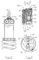
- An inner tube has the notation 2 and an outer tube the notation 3.
- the said pipes 2 and 3 are herewith disposed relative to each other such that a gap 4 is configured between the tubes.
- the inner tube 2 forms a cylinder in the shock absorber.
- a piston 5 which operates in the chambers 6, 7 of the cylinder.
- the bottom side of the piston is shown by 8 and its top side by 9.
- a piston rod which is fixed in the piston is shown by 10.
- the shock absorber is also provided with a main spring 11 disposed between a first flange 12 on the outside of the tube 3 and a second flange 13 fixed to the piston rod 10.
- a securing mechanism 14 having a recess 15 for the said securement of a type which is known per se.
- the securement can herewith be effected in a chassis on a vehicle (e.g. motor-cycle), the motion of the associated wheel (not shown) of which is to be damped by means of the shock absorber.
- the shock absorber is also provided with a unit A which is fastened to the first ends 2a and 3a of the tubes 2, 3.
- the unit A is provided with recesses which, in Figure 1, have been symbolised by 16.
- the unit A is also provided with a second securing element 17 and an associated aperture 18.
- the shock absorber is attached by the latter securing element to the particular wheel or equivalent, the motion of which is to be damped with the shock absorber in question.
- the tube 2 is provided with a partition 19 exhibiting a cylindrical wall element 19a.
- the wall 19 is provided with a retaining mechanism 20 and one or more medium passages 21.
- the wall is fixed by means of a guide pin 22.
- the piston and the piston rod can perform compression and expansion motions in the directions of the arrows 23.
- the piston and the piston rod are shown in Figure 1 in a fully expanded position which is achieved by means of the main spring 11.
- the compression motions take place counter to the action of the said main spring 11.
- the piston 5 is sealed against the inner surface of the tube 2 by means of seals of a known type, in a manner which is known per se.
- the piston rod is secured in the piston 5 in a manner which is likewise known. The said seals and fastenings will not therefore be described here in any greater detail.
- the unit A can be screwed tightly into the inner tube by means of threads 24.
- the thread in the unit A is located on a tubular element 25.
- the said element 25 is sealed against the inner surface of the tube 3 by means of a seal 26.
- the inner wall is sealed against the inner surface of the tube 2 by means of a seal 27.
- the shock absorber is provided, at the back or at the top, with a forked element 28 and the inner tube 2 is screwed tightly into the forked element via threads 29.
- the outer element or outer tube 3 is fixed in the longitudinal direction by means of a stop surface 28a on the forked element and a stop surface on the said unit A.
- the outer tube 3 is sealed against the forked element by means of a seal 30.
- the gap 4 opens out into the interior of the inner tube, above the piston 5, via an opening 4a and behind the partition 19 (viewed from the piston) via an opening 4b.
- the piston performs its compression motion from the position shown in Figure 1
- the medium located in the chamber 6 is compressed and forced out, via the said medium passages 21, to the unit A, which, as stated below, exhibits manually adjustable adjustment mechanisms for the bleeding function and damping level of the shock absorber.
- the medium After passing via the adjustment mechanisms, the medium is transported on the basis of the force generated by the piston, back through one or more clack valves and onwards, via a recess or recesses 31, towards the gap 4.
- the transportation takes place, therefore, in the direction of the arrow 32, to the chamber 7 on the top side of the piston.
- the adjustment mechanisms are arranged so as to be easily accessible via the said outwardly-directed recesses (cf. 16 in Figure 1).
- Figure 2 shows four recesses 16a, 16b, 16c and 16d.
- the adjustment mechanisms are easily accessibly by hand via the said recesses.
- Figure 3 shows an embodiment of the shock absorber along the section A-A in Figure 2.
- a first adjustment mechanism 16b' is indicated and has a location in the recess 16b according to Figure 2.
- the said first adjustment mechanism is intended for manual adjustment of the damping level in the direction of compression of the shock absorber.
- a second adjustment mechanism 16d' is arranged having location in the recess 16d according to Figure 2. The second adjustment mechanism is utilised for adjustment of the bleeding function in the direction of compression.
- the recesses 16a and 16c have corresponding adjustment mechanisms for adjustment of the damping level and bleeding function in the direction of expansion.
- a manually adjustable level-regulating knob 34 is arranged for manual adjustment and can be locked tight by means of a stop screw 35.
- the throttling function 36 in the adjustment mechanism in question is pre-tensioned or adjusted by means of the level-regulating knob.
- the second mechanism 16d' exhibits a level-regulating knob 37 and a throttling mechanism 38 which is adjustable by means of the level-regulating knob.
- the medium is introduced into the chamber 45 via a channel 41, in which the said throttling function is disposed, and conducted onwards, via a passage 40 and 39, back again to the shock absorber.
- medium is introduced in a corresponding manner via a recess 43, which is in contact, via the said throttling function 38, with a return channel 42. Medium is conducted from the return channel back to the particular side of the piston.
- the gap-shaped channel 4 can preferably extend around and along the entire periphery of the shock absorber. Alternatively, only parts of the periphery can be occupied by the said channel or channels.
- large piston areas are here meant piston areas on pistons of diameters between 30 and 60 mm and which substantially exceed the area on the piston rod, a typical diameter of which measures 10-18 mm.
- the inner and outer tubes are thus essentially of equal length and the outer tube is fixed in its longitudinal direction by means of the unit A and the said forked element. Both the forked element and the unit A are fastened/screwed tightly onto the inner tube.
- the wall element is anchored internally in the unit A and the openings of the channel are disposed at the respective ends of the tubes 2 and 3.
- the element 14 is screwed tightly into the piston rod and is provided partly with securing mechanisms, partly with the flange 13.
- valve 63 closes off the passage or the throttling 36 by virtue of the flow force being added, in this case, to the closing force (adjustable) of the valve, which force would therefore be bound to be surmounted by the flow force in the direction 62.
- the valve is adjustable according to the above, preferably manually, by means of the actuating mechanism 34.
- the direction of motion of the valve is shown by 65.
- the leakage valve (bleeder) 16d' is also adjusted in order to grant a greater or lesser desired passage of medium in the direction 62.
- the medium flow is divided towards the accumulator via the channel 50 and towards the bottom side of the piston via the channel 51.
- Incorporated in the latter are the one-way function or clack valve 44'.
- the unit 59 functions in a manner corresponding to the unit 58 for the expansion motion, where medium is transferred in a corresponding manner, in the direction of the arrows 66, via valve mechanisms 16a', 16c' or 44''.
- the difference is that medium displaced by the piston rod during compression is conducted back in the direction of the arrow 67, via the conduit 56, to the top side of the piston.
- the said valves can be constituted by known constructions and operate on known functions.
- the adjustment and control functions can also be realised in a known manner.
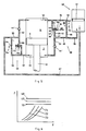
- the preferably manually adjustable valves can be used to determine, for example, curves on the force/velocity graph according to Figure 6.
- Levels 68, 69, 70 are determined by adjustment or control of the valve 16b' (only the compression curve is shown in Figure 6) or 16a' (for the non-represented expansion curve).
- the leakage valve 16d' (compression) or 16c' (expansion) is used to determine slopes of the curve or lines of the curves 71, 72, 73.
- the respective curve can thus be composed by the said adjustment or controlling function and adjustments can thus, for example, be carried out in order to eliminate hysteresis effects, adapt the damping function to a certain track profile etc.
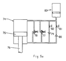
- a cylinder is designated 74, a piston 75 and a piston rod 76.
- the cylinder is connected to an arrangement including two adjustable and/or controllable valves 77 and 78.
- the arrangement includes also two one-way flow arrangement 79 and 80 and two adjustable bleed valve arrangement 81 and 82.
- the valves 77, 80, 81 are allocated to the compression movement and 78, 79 and 82 to the expansion movement. Valves 77 and 78 allow fluid flow in one respective direction only.
- the bleed valves 81 and 82 are adjustable in a known way. In this case the bleed flow is conducted only through the non--return valves 79 and 80, respectively.
- the pressure in the accumulator 83 is rather high, for example 30-40 bar.
Landscapes
- Engineering & Computer Science (AREA)
- General Engineering & Computer Science (AREA)
- Mechanical Engineering (AREA)
- Physics & Mathematics (AREA)
- Fluid Mechanics (AREA)
- Fluid-Damping Devices (AREA)
Priority Applications (1)
| Application Number | Priority Date | Filing Date | Title |
|---|---|---|---|
| EP97850127A EP0816711A3 (de) | 1992-12-09 | 1993-06-15 | Verstellbarer Kolbenstossdämpfer |
Applications Claiming Priority (2)
| Application Number | Priority Date | Filing Date | Title |
|---|---|---|---|
| SE9203706 | 1992-12-09 | ||
| SE9203706A SE506443C2 (sv) | 1992-12-09 | 1992-12-09 | Anordning vid stötdämpare |
Related Child Applications (1)
| Application Number | Title | Priority Date | Filing Date |
|---|---|---|---|
| EP97850127A Division EP0816711A3 (de) | 1992-12-09 | 1993-06-15 | Verstellbarer Kolbenstossdämpfer |
Publications (2)
| Publication Number | Publication Date |
|---|---|
| EP0601982A1 true EP0601982A1 (de) | 1994-06-15 |
| EP0601982B1 EP0601982B1 (de) | 1998-04-01 |
Family
ID=20388074
Family Applications (2)
| Application Number | Title | Priority Date | Filing Date |
|---|---|---|---|
| EP93850133A Expired - Lifetime EP0601982B1 (de) | 1992-12-09 | 1993-06-15 | Vorrichtung für Stossdämpfer |
| EP97850127A Withdrawn EP0816711A3 (de) | 1992-12-09 | 1993-06-15 | Verstellbarer Kolbenstossdämpfer |
Family Applications After (1)
| Application Number | Title | Priority Date | Filing Date |
|---|---|---|---|
| EP97850127A Withdrawn EP0816711A3 (de) | 1992-12-09 | 1993-06-15 | Verstellbarer Kolbenstossdämpfer |
Country Status (5)
| Country | Link |
|---|---|
| US (1) | US5460355A (de) |
| EP (2) | EP0601982B1 (de) |
| JP (1) | JP3462243B2 (de) |
| DE (1) | DE69317737T2 (de) |
| SE (1) | SE506443C2 (de) |
Cited By (16)
| Publication number | Priority date | Publication date | Assignee | Title |
|---|---|---|---|---|
| EP0715091A3 (de) * | 1994-12-03 | 1998-04-08 | FICHTEL & SACHS AG | Schwingungsdämpfer mit einstellbarer Dämpfkraft |
| EP1085232A1 (de) * | 1998-03-31 | 2001-03-21 | Donerre Amortisseur | Einstellvorrichtung eines hydraulischen Stossdämpfers |
| FR2802597A1 (fr) * | 1999-12-07 | 2001-06-22 | Mannesmann Sachs Ag | Amortisseur d'oscillations a force d'amortissement reglable |
| EP1106403A3 (de) * | 1994-12-03 | 2001-07-04 | Mannesmann Sachs Aktiengesellschaft | Schwingungsdämpfer mit einstellbarer Dämpfkraft |
| EP1130280A1 (de) * | 2000-02-29 | 2001-09-05 | Gkn Westland Helicopters Limited | Schwingungsdämpfungsvorrichtung |
| US6443272B1 (en) | 1999-02-10 | 2002-09-03 | Sachs Race Engineering Gmbh | Vibration damper with adjustable damping force |
| WO2006125624A1 (de) * | 2005-05-27 | 2006-11-30 | Daimlerchrysler Ag | Vorrichtung und verfahren zur beeinflussung der dämpfungskraftcharakteristik einer fahrwerksaufhängung eines kraftfahrzeugs |
| WO2006125626A1 (de) * | 2005-05-27 | 2006-11-30 | Daimlerchrysler Ag | Vorrichtung und verfahren zur beeinflussung der dämpfungskraftcharakteristik einer fahrwerkaufhängung eines kraftfahrzeugs |
| US7607522B2 (en) | 2004-11-18 | 2009-10-27 | öHLINS RACING AB | Shock absorber for vehicles |
| FR2933951A1 (fr) * | 2008-07-21 | 2010-01-22 | Veleance | Mecanisme de controle d'inclinaison |
| FR2933950A1 (fr) * | 2008-07-21 | 2010-01-22 | Veleance | Dispositif mecanique de controle d'inclinaison |
| WO2012041786A1 (en) * | 2010-09-28 | 2012-04-05 | Norgren Gmbh | Damping cylinder |
| US8695765B2 (en) | 2006-09-21 | 2014-04-15 | Ohins Racing AB | Shock absorber having resilient device in rebound chamber |
| NL2010038C2 (en) * | 2012-12-21 | 2014-06-24 | Koni Bv | Shock absorber. |
| US9334011B2 (en) | 2010-05-14 | 2016-05-10 | Specialized Bicycle Components, Inc. | Bicycle frame |
| EP2643611B1 (de) * | 2010-03-15 | 2017-09-27 | Trysome Limited | Frequenzabhängige dämpfung |
Families Citing this family (25)
| Publication number | Priority date | Publication date | Assignee | Title |
|---|---|---|---|---|
| US6079725A (en) * | 1997-07-24 | 2000-06-27 | Iron Horse Productions, Inc. | Folding wheelchair with improved suspension system |
| JP2002532313A (ja) | 1998-12-18 | 2002-10-02 | ジェネラル ダイナミックス オードナンス アンド タクティカル システムズ、インコーポレイテッド | オートバイ・サスペンション構成要素 |
| JP4294901B2 (ja) * | 1999-12-01 | 2009-07-15 | グラフ,アンリ | 椎間安定装置 |
| US7066957B2 (en) * | 1999-12-29 | 2006-06-27 | Sdgi Holdings, Inc. | Device and assembly for intervertebral stabilization |
| FR2817461B1 (fr) * | 2000-12-01 | 2003-08-15 | Henry Graf | Dispositif de stabilisation intervertebral |
| DE10239140A1 (de) * | 2002-08-27 | 2004-03-11 | Bayerische Motoren Werke Ag | Motorrad mit einer verstellbaren Hinterradschwinge zum Absetzen auf einem ausklappbaren Hauptständer |
| DE10315088A1 (de) * | 2003-04-02 | 2004-10-14 | Gustav Magenwirth Gmbh & Co. Kg | Dämpfungssystem |
| SE532116C2 (sv) | 2007-02-06 | 2009-10-27 | Oehlins Racing Ab | Stötdämpare med flödeskanaler |
| DE102007021854B3 (de) * | 2007-05-10 | 2008-08-28 | Stabilus Gmbh | Kolben-Zylinder-Einheit |
| JP4902483B2 (ja) * | 2007-09-28 | 2012-03-21 | 株式会社ショーワ | 油圧緩衝器 |
| US8733519B2 (en) * | 2009-01-23 | 2014-05-27 | Jri Development Group, Llc | Linear impelled module damper |
| JP5415992B2 (ja) | 2010-02-25 | 2014-02-12 | 株式会社ショーワ | 油圧緩衝器 |
| DE102012007519A1 (de) * | 2012-04-17 | 2013-10-17 | Rheinisch-Westfälische Technische Hochschule Aachen | Verfahren zur Fahrwerksabstimmung eines Kraftfahrzeugs und Federbein |
| JP2014122656A (ja) | 2012-12-20 | 2014-07-03 | Yamaha Motor Hydraulic System Co Ltd | ショックアブソーバ |
| JP6082261B2 (ja) * | 2013-02-04 | 2017-02-15 | Kyb株式会社 | 緩衝器 |
| CN103711828B (zh) * | 2014-01-06 | 2015-10-28 | 浙江中兴减震器制造有限公司 | 三筒自适应式防侧倾减震器 |
| IT201700066407A1 (it) * | 2017-06-15 | 2018-12-15 | Formula S A S Di Formula Group S R L & C | Ammortizzatore regolabiile in compressione e in ritorno |
| USD866408S1 (en) | 2017-08-28 | 2019-11-12 | Qa1 Precision Products, Inc. | Shock absorber |
| US11105390B2 (en) | 2017-08-28 | 2021-08-31 | Qa1 Precision Products, Inc. | Shock absorber with dry valving |
| USD872837S1 (en) | 2017-08-28 | 2020-01-14 | Qa1 Precision Products, Inc. | Bleed needle |
| USD869259S1 (en) | 2017-08-28 | 2019-12-10 | Qa1 Precision Products, Inc. | Valve component |
| US11085502B2 (en) | 2017-08-28 | 2021-08-10 | Qa1 Precision Products, Inc. | Bleed needle for a hydraulic system |
| EP3951209A1 (de) * | 2020-08-04 | 2022-02-09 | Öhlins Racing AB | Ventilanordnung zur bereitstellung verbesserter dämpfkraftkennlinien bei höheren hubgeschwindigkeiten in einem stossdämpfer |
| US12545070B2 (en) * | 2021-09-29 | 2026-02-10 | Hitachi Astemo, Ltd. | Suspension system and controller |
| JP2024104396A (ja) * | 2023-01-24 | 2024-08-05 | キャタピラー エス エー アール エル | リリーフ設定圧調整システム |
Citations (4)
| Publication number | Priority date | Publication date | Assignee | Title |
|---|---|---|---|---|
| GB778281A (en) * | 1952-01-15 | 1957-07-03 | Chermino Sturari | A hydro-pneumatic shock-absorber, particularly for motor cars |
| BE686322A (de) * | 1965-09-03 | 1967-02-15 | ||
| GB2159234A (en) * | 1984-05-17 | 1985-11-27 | Boge Gmbh | Hydraulic damper with adjustable bypass |
| DE4007261A1 (de) * | 1990-03-08 | 1991-09-12 | Boge Ag | Regelbarer schwingungsdaempfer |
Family Cites Families (14)
| Publication number | Priority date | Publication date | Assignee | Title |
|---|---|---|---|---|
| FR686322A (fr) * | 1928-12-13 | 1930-07-24 | Ig Farbenindustrie Ag | Procédé de préparation de charbon actif en grains |
| US2780321A (en) * | 1952-01-15 | 1957-02-05 | Sturari Chermino | Adjustable shock absorber |
| DE1242946B (de) * | 1962-10-03 | 1967-06-22 | Rheinmetall Gmbh | Hydraulischer Schwingungsdaempfer, insbesondere fuer Fahrzeuge |
| DE1480136A1 (de) * | 1964-12-02 | 1969-05-14 | Teves Gmbh Alfred | Federbein,insbesondere fuer Kraftfahrzeuge |
| US3399905A (en) * | 1965-08-27 | 1968-09-03 | Arthur E Vogel | Controlled suspension system for vehicles |
| US3610656A (en) * | 1970-02-24 | 1971-10-05 | Gen Motors Corp | Self-pumping height controller and damper |
| JPS53117170A (en) * | 1977-03-22 | 1978-10-13 | Honda Motor Co Ltd | Regulator of damping force changing mechanism for rolling stock |
| JPS54111064A (en) * | 1978-02-18 | 1979-08-31 | Honda Motor Co Ltd | Damping-force adjusting apparatus in hydraulic shock- absorber |
| DE3413815C2 (de) * | 1984-04-12 | 1987-03-12 | Boge Gmbh, 5208 Eitorf | Hydraulischer, sperrbarer Zweirohr-Schwingungsdämpfer |
| DE3524863A1 (de) * | 1985-04-12 | 1986-10-30 | Robert Bosch Gmbh, 7000 Stuttgart | Verfahren und vorrichtung zum steuern der federhaerte, insbesondere bei fahrzeugen |
| US4709791A (en) * | 1985-05-23 | 1987-12-01 | Enidine Incorporated | Adjustable double-acting damper |
| JPH035224A (ja) * | 1989-05-31 | 1991-01-11 | Chuo Spring Co Ltd | 車輌用スタビライザ装置 |
| US5111917A (en) * | 1991-02-26 | 1992-05-12 | Maremont Corporation | Dampener valving control mechanism |
| DE4115061A1 (de) * | 1991-05-08 | 1991-11-14 | Mazda Motor | Radaufhaengung bei einem kraftfahrzeug |
-
1992
- 1992-12-09 SE SE9203706A patent/SE506443C2/sv not_active IP Right Cessation
-
1993
- 1993-06-15 DE DE69317737T patent/DE69317737T2/de not_active Expired - Fee Related
- 1993-06-15 EP EP93850133A patent/EP0601982B1/de not_active Expired - Lifetime
- 1993-06-15 EP EP97850127A patent/EP0816711A3/de not_active Withdrawn
- 1993-12-06 US US08/163,071 patent/US5460355A/en not_active Expired - Lifetime
- 1993-12-09 JP JP30933693A patent/JP3462243B2/ja not_active Expired - Fee Related
Patent Citations (4)
| Publication number | Priority date | Publication date | Assignee | Title |
|---|---|---|---|---|
| GB778281A (en) * | 1952-01-15 | 1957-07-03 | Chermino Sturari | A hydro-pneumatic shock-absorber, particularly for motor cars |
| BE686322A (de) * | 1965-09-03 | 1967-02-15 | ||
| GB2159234A (en) * | 1984-05-17 | 1985-11-27 | Boge Gmbh | Hydraulic damper with adjustable bypass |
| DE4007261A1 (de) * | 1990-03-08 | 1991-09-12 | Boge Ag | Regelbarer schwingungsdaempfer |
Cited By (22)
| Publication number | Priority date | Publication date | Assignee | Title |
|---|---|---|---|---|
| EP0715091A3 (de) * | 1994-12-03 | 1998-04-08 | FICHTEL & SACHS AG | Schwingungsdämpfer mit einstellbarer Dämpfkraft |
| EP1106403A3 (de) * | 1994-12-03 | 2001-07-04 | Mannesmann Sachs Aktiengesellschaft | Schwingungsdämpfer mit einstellbarer Dämpfkraft |
| EP1085232A1 (de) * | 1998-03-31 | 2001-03-21 | Donerre Amortisseur | Einstellvorrichtung eines hydraulischen Stossdämpfers |
| US6443272B1 (en) | 1999-02-10 | 2002-09-03 | Sachs Race Engineering Gmbh | Vibration damper with adjustable damping force |
| FR2802597A1 (fr) * | 1999-12-07 | 2001-06-22 | Mannesmann Sachs Ag | Amortisseur d'oscillations a force d'amortissement reglable |
| EP1130280A1 (de) * | 2000-02-29 | 2001-09-05 | Gkn Westland Helicopters Limited | Schwingungsdämpfungsvorrichtung |
| US6454206B2 (en) | 2000-02-29 | 2002-09-24 | Gkn Westland Helicopters Limited | Vibration damping apparatus |
| US7607522B2 (en) | 2004-11-18 | 2009-10-27 | öHLINS RACING AB | Shock absorber for vehicles |
| WO2006125624A1 (de) * | 2005-05-27 | 2006-11-30 | Daimlerchrysler Ag | Vorrichtung und verfahren zur beeinflussung der dämpfungskraftcharakteristik einer fahrwerksaufhängung eines kraftfahrzeugs |
| WO2006125626A1 (de) * | 2005-05-27 | 2006-11-30 | Daimlerchrysler Ag | Vorrichtung und verfahren zur beeinflussung der dämpfungskraftcharakteristik einer fahrwerkaufhängung eines kraftfahrzeugs |
| US8695765B2 (en) | 2006-09-21 | 2014-04-15 | Ohins Racing AB | Shock absorber having resilient device in rebound chamber |
| FR2933950A1 (fr) * | 2008-07-21 | 2010-01-22 | Veleance | Dispositif mecanique de controle d'inclinaison |
| WO2010010245A1 (fr) * | 2008-07-21 | 2010-01-28 | Veleance | Dispositif mecanique de controle d'inclinaison |
| FR2933951A1 (fr) * | 2008-07-21 | 2010-01-22 | Veleance | Mecanisme de controle d'inclinaison |
| EP2643611B1 (de) * | 2010-03-15 | 2017-09-27 | Trysome Limited | Frequenzabhängige dämpfung |
| US9334011B2 (en) | 2010-05-14 | 2016-05-10 | Specialized Bicycle Components, Inc. | Bicycle frame |
| WO2012041786A1 (en) * | 2010-09-28 | 2012-04-05 | Norgren Gmbh | Damping cylinder |
| CN103228945A (zh) * | 2010-09-28 | 2013-07-31 | 诺格伦有限责任公司 | 阻尼筒 |
| CN103228945B (zh) * | 2010-09-28 | 2016-06-22 | 诺格伦有限责任公司 | 阻尼筒 |
| NL2010038C2 (en) * | 2012-12-21 | 2014-06-24 | Koni Bv | Shock absorber. |
| WO2014104876A1 (en) * | 2012-12-21 | 2014-07-03 | Koni B.V. | Shock absorber |
| US9982740B2 (en) | 2012-12-21 | 2018-05-29 | Koni B.V. | Shock absorber |
Also Published As
| Publication number | Publication date |
|---|---|
| SE9203706L (sv) | 1994-06-10 |
| DE69317737D1 (de) | 1998-05-07 |
| JPH06221365A (ja) | 1994-08-09 |
| JP3462243B2 (ja) | 2003-11-05 |
| US5460355A (en) | 1995-10-24 |
| EP0816711A2 (de) | 1998-01-07 |
| SE506443C2 (sv) | 1997-12-15 |
| DE69317737T2 (de) | 1998-07-30 |
| EP0601982B1 (de) | 1998-04-01 |
| EP0816711A3 (de) | 1999-02-03 |
| SE9203706D0 (sv) | 1992-12-09 |
Similar Documents
| Publication | Publication Date | Title |
|---|---|---|
| EP0601982B1 (de) | Vorrichtung für Stossdämpfer | |
| DE60211231T2 (de) | Kolben- und Kolbenstangeneinheit für pneumatisch betätigte, einstellbare Dämpfung | |
| DE3231739C2 (de) | ||
| US5295563A (en) | Active suspension actuator with control flow through the piston rod | |
| JP5933598B2 (ja) | バネなし緩衝装置兼用懸架装置、及び使用方法 | |
| US5386892A (en) | Hydraulic shock absorber with shutters | |
| DE4401393C1 (de) | Hydraulischer, verstellbarer Schwingungsdämpfer für Kraftfahrzeuge | |
| JP3524040B2 (ja) | ショックアブソーバ | |
| US5649611A (en) | Damping force control type hydraulic shock absorber | |
| US5738191A (en) | Vibration damper | |
| DE3816102C1 (de) | ||
| US6213261B1 (en) | Hydropneumatic spring | |
| KR20010101197A (ko) | 완충장치 | |
| CN103939516A (zh) | 具有数字阀的阻尼器 | |
| EP1203712B1 (de) | Zusammengesetztes Verbindungssystem für eine Fahrzeugaufhängung | |
| US20090145706A1 (en) | Arrangement for telescopic fork leg with parallel damping | |
| DE4212078A1 (de) | Endlagendämpfer | |
| EP2126403A1 (de) | Verfahren und anpassung von dämpfeigenschaften bei einem stossdämpfer | |
| US6006873A (en) | Industrial shock absorber | |
| DE3526156A1 (de) | Lastabhaengiges feder-daempfer-aggregat | |
| DE19757276A1 (de) | Hydraulischer, verstellbarer Schwingungsdämpfer | |
| US5984059A (en) | Suspension system | |
| US20010006269A1 (en) | Vehicle suspension apparatus | |
| CA2361322A1 (en) | Improved shock absorber | |
| KR940004232A (ko) | 쇼크 업소버 |
Legal Events
| Date | Code | Title | Description |
|---|---|---|---|
| PUAI | Public reference made under article 153(3) epc to a published international application that has entered the european phase |
Free format text: ORIGINAL CODE: 0009012 |
|
| AK | Designated contracting states |
Kind code of ref document: A1 Designated state(s): DE FR GB IT NL |
|
| 17P | Request for examination filed |
Effective date: 19940617 |
|
| 17Q | First examination report despatched |
Effective date: 19950629 |
|
| GRAG | Despatch of communication of intention to grant |
Free format text: ORIGINAL CODE: EPIDOS AGRA |
|
| GRAG | Despatch of communication of intention to grant |
Free format text: ORIGINAL CODE: EPIDOS AGRA |
|
| GRAH | Despatch of communication of intention to grant a patent |
Free format text: ORIGINAL CODE: EPIDOS IGRA |
|
| GRAH | Despatch of communication of intention to grant a patent |
Free format text: ORIGINAL CODE: EPIDOS IGRA |
|
| GRAA | (expected) grant |
Free format text: ORIGINAL CODE: 0009210 |
|
| AK | Designated contracting states |
Kind code of ref document: B1 Designated state(s): DE FR GB IT NL |
|
| DX | Miscellaneous (deleted) | ||
| ITF | It: translation for a ep patent filed | ||
| ET | Fr: translation filed | ||
| REF | Corresponds to: |
Ref document number: 69317737 Country of ref document: DE Date of ref document: 19980507 |
|
| PLBE | No opposition filed within time limit |
Free format text: ORIGINAL CODE: 0009261 |
|
| STAA | Information on the status of an ep patent application or granted ep patent |
Free format text: STATUS: NO OPPOSITION FILED WITHIN TIME LIMIT |
|
| 26N | No opposition filed | ||
| REG | Reference to a national code |
Ref country code: GB Ref legal event code: IF02 |
|
| PGFP | Annual fee paid to national office [announced via postgrant information from national office to epo] |
Ref country code: FR Payment date: 20040503 Year of fee payment: 12 |
|
| PGFP | Annual fee paid to national office [announced via postgrant information from national office to epo] |
Ref country code: NL Payment date: 20040528 Year of fee payment: 12 |
|
| PG25 | Lapsed in a contracting state [announced via postgrant information from national office to epo] |
Ref country code: IT Free format text: LAPSE BECAUSE OF NON-PAYMENT OF DUE FEES;WARNING: LAPSES OF ITALIAN PATENTS WITH EFFECTIVE DATE BEFORE 2007 MAY HAVE OCCURRED AT ANY TIME BEFORE 2007. THE CORRECT EFFECTIVE DATE MAY BE DIFFERENT FROM THE ONE RECORDED. Effective date: 20050615 |
|
| PG25 | Lapsed in a contracting state [announced via postgrant information from national office to epo] |
Ref country code: NL Free format text: LAPSE BECAUSE OF NON-PAYMENT OF DUE FEES Effective date: 20060101 |
|
| PG25 | Lapsed in a contracting state [announced via postgrant information from national office to epo] |
Ref country code: FR Free format text: LAPSE BECAUSE OF NON-PAYMENT OF DUE FEES Effective date: 20060228 |
|
| NLV4 | Nl: lapsed or anulled due to non-payment of the annual fee |
Effective date: 20060101 |
|
| REG | Reference to a national code |
Ref country code: FR Ref legal event code: ST Effective date: 20060228 |
|
| PGFP | Annual fee paid to national office [announced via postgrant information from national office to epo] |
Ref country code: DE Payment date: 20080620 Year of fee payment: 16 |
|
| PGFP | Annual fee paid to national office [announced via postgrant information from national office to epo] |
Ref country code: GB Payment date: 20080620 Year of fee payment: 16 |
|
| GBPC | Gb: european patent ceased through non-payment of renewal fee |
Effective date: 20090615 |
|
| PG25 | Lapsed in a contracting state [announced via postgrant information from national office to epo] |
Ref country code: GB Free format text: LAPSE BECAUSE OF NON-PAYMENT OF DUE FEES Effective date: 20090615 |
|
| PG25 | Lapsed in a contracting state [announced via postgrant information from national office to epo] |
Ref country code: DE Free format text: LAPSE BECAUSE OF NON-PAYMENT OF DUE FEES Effective date: 20100101 |