EP0602045B1 - Dispositif de tri de pieces de monnaie comportant un disque et des files d'attente multiples - Google Patents
Dispositif de tri de pieces de monnaie comportant un disque et des files d'attente multiples Download PDFInfo
- Publication number
- EP0602045B1 EP0602045B1 EP92910966A EP92910966A EP0602045B1 EP 0602045 B1 EP0602045 B1 EP 0602045B1 EP 92910966 A EP92910966 A EP 92910966A EP 92910966 A EP92910966 A EP 92910966A EP 0602045 B1 EP0602045 B1 EP 0602045B1
- Authority
- EP
- European Patent Office
- Prior art keywords
- wall
- coins
- disc
- channel
- coin
- Prior art date
- Legal status (The legal status is an assumption and is not a legal conclusion. Google has not performed a legal analysis and makes no representation as to the accuracy of the status listed.)
- Expired - Lifetime
Links
- 238000004064 recycling Methods 0.000 description 4
- 230000000712 assembly Effects 0.000 description 2
- 238000000429 assembly Methods 0.000 description 2
- 230000000694 effects Effects 0.000 description 2
- 238000012986 modification Methods 0.000 description 2
- 230000004048 modification Effects 0.000 description 2
- 230000003247 decreasing effect Effects 0.000 description 1
- 230000009977 dual effect Effects 0.000 description 1
- 239000000463 material Substances 0.000 description 1
- 239000002184 metal Substances 0.000 description 1
- 239000002356 single layer Substances 0.000 description 1
- 239000007787 solid Substances 0.000 description 1
- 238000011144 upstream manufacturing Methods 0.000 description 1
Images








Classifications
-
- G—PHYSICS
- G07—CHECKING-DEVICES
- G07D—HANDLING OF COINS OR VALUABLE PAPERS, e.g. TESTING, SORTING BY DENOMINATIONS, COUNTING, DISPENSING, CHANGING OR DEPOSITING
- G07D3/00—Sorting a mixed bulk of coins into denominations
- G07D3/12—Sorting coins by means of stepped deflectors
- G07D3/128—Rotary devices
-
- G—PHYSICS
- G07—CHECKING-DEVICES
- G07D—HANDLING OF COINS OR VALUABLE PAPERS, e.g. TESTING, SORTING BY DENOMINATIONS, COUNTING, DISPENSING, CHANGING OR DEPOSITING
- G07D9/00—Counting coins; Handling of coins not provided for in the other groups of this subclass
- G07D9/008—Feeding coins from bulk
Definitions
- a coin sorter comprising a disc rotatable by a motor and a stationary sorting head having a lower surface parallel to the upper surface of the rotatable disc and spaced slightly therefrom.
- a hopper is positioned above an opening in the sorting head and coins to be sorted are inserted through this hopper.
- the sorting head is configured with a surface or recesses and with edges which direct the movement of coins from the centre of the sorting head to circumferentially spaced coin ejection assemblies about the periphery of guide plate.
- the first recess forms coins in a single file and directs the coins outward in a spiral.
- a hopper 10 receives coins of mixed denominations and feeds them through a central feed aperture in an annular sorting head or guide plate 12. As the coins pass through the feed aperture, they are deposited on the top surface of a rotatable disc 13. This disc 13 is mounted for rotation on a stub shaft (not shown) and driven by an electric motor 14.
- the disc 13 comprises a resilient pad 16, preferably made of a resilient rubber or polymeric material, bonded to the top surface of a solid metal disc 17.
- the outwardly moving coins initially enter an annular recess 20 formed in the underside of the sorting head 12 and extending around a major portion of the inner periphery of the sorting head.
- the outer wall 21 of the recess 20 extends downwardly to the lowermost surface 22 of the sorting head, which is preferably spaced from the top surface of the pad 16 by a distance e.g., 0.010 inch, which is slightly less, e.g., 0.010 inch, than the thickness of the thinnest coin. Consequently, the initial radial movement of the coins is terminated when they engage the wall 21 of the recess 20, though the coins continue to move circumferentially along the wall 21 by the rotational movement of the pad 16. Overlapping coins which only partially enter the recess 20 are stripped apart by a notch 20a formed in the top surface of the recess 20 along its inner edge (see FIG. 2).
- the only portion of the central opening of the guide plate 12 which does not open directly into the recess 20 is that sector of the periphery which is occupied by a land 23 whose lower surface is at a slightly higher elevation than the lowermost surface 22 of the sorting head.
- the upstream end of the land 23 forms a ramp 23a (FIG. 2).
- a coin When such a coin has only partially entered the recess 20, it engages the ramp 23a on the leading edge of the land 23.
- the ramp 23a presses the coin downwardly into the resilient pad 16, which causes the coin to be recirculated.
- the spiral channel 30 causes coins of different thicknesses and/or diameters to follow different paths which facilitate the queuing of the coins and increase the coin throughput rate. Though following different paths, the coins of all denominations exit the spiral channel 30 with a common edge (the outer edges of all coins) aligned at the same or approximately the same radial position so that the opposite (inner) edges of the coins can be used for sorting.
- the spiral channel 30 includes an inner channel region defined by an inner wall 31 and a middle wall 32, and an outer channel region defined by the middle wall 32 and an outer wall 33.
- the inner channel region is deeper than the outer channel region, and the middle wall 32 is tapered to enable coins to pass under that wall under certain conditions to be described below.
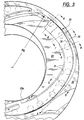
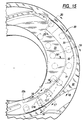
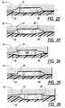
- Coins of different thicknesses and/or diameters follow different paths within one or both of the channel regions, and these different paths have been separately illustrated in FIGS. 3-8, 9-14, 15-20, 21-26, 27-32 and 33-38.
- FIGS. 3-8 illustrate the path followed by small, thin coins in a single layer.
- These are coins having a diameter smaller than the width of the channel region between the inner wall 31 and the middle wall 32 of the channel, and thin enough to avoid being pressed into the resilient pad.
- Such coins are guided through the channel by the middle wall 32, exiting with their outer edges at the desired gaging radius R g .
- the outer region of the channel, between the middle wall 32 and the outer wall 33 is spaced from the resilient pad by a distance that is less than the thickness of the thinnest coin, the only coins that pass outwardly over the middle wall 32 are those that are wider than the radial distance between the inner and middle walls; such coins are forced over the middle wall 32 by the inner wall 31 of the channel.
- Coins guided by either the middle wall 32 or the outer wall 33 have their outer edges aligned at the same gaging radius R g because the middle and outer walls merge at the end of the spiral channel 30.
- the dual spiral channel 30 is particularly useful in queuing small coins which enter the channel in staggered relationship, as illustrated in FIGS. 9-14, for example.
- the spacing between any pair of successive coins gradually increases due to the increasing radius of the coin path.
- coins guided by the inner wall 31 move ahead of coins guided by the middle wall 32, because the radius of the inner wall 31 increases at a faster rate than that of the middle wall 32.
- the distance between the inner and middle walls 31 and 32 is progressively decreased.
- the effect of all these variables is to gradually bring coins which are staggered at the inlet end of the channel 30 into single file by the time they reach the point where the distance between the inner and middle walls 31 and 32 at its minimum. This alignment of the coins into a single file is achieved progressively along the length of the spiral channel, so that the coins move smoothly and continuously through the channel at high throughput rates.
- the illustrative spiral channel 30 also strips apart stacked or shingled coins, as illustrated in FIGS. 15-20.
- the combined thickness of a pair of stacked or shingled coin is great enough to cause the lower coin in that pair to be pressed into the resilient pad. Consequently, that pair of coins will be rotated concentrically with the disc, as illustrated by the coin pairs C16, and C17 in FIGS. 15-17.
- the inner wall 31 spirals outwardly, the upper coin will eventually engage the upper vertical portion of the inner wall 31, as illustrated in FIG. 17, and the lower coin will engage the tapered lower portion of the inner wall, as also illustrated in FIG. 17, and pass under that wall (see FIG. 18).
- the latter coin will be recirculated back to the entry region of the sorting head and will later re-enter the spiral channel.
- the channel 30 is preferably designed so that the minimum distance between the inner and middle walls, i.e., at the location of coin C24 in FIG. 21, is about the same as the diameter of the smallest coin that is thick enough to be pressed into the resilient pad in the channel region between the inner and middle walls. Consequently, when such a coin reaches the point where that distance is a minimum, the outer edge of the coin is adjacent the middle wall, as shown in FIG. 24.
- the radius of the middle wall 32 remains constant at the desired gaging radius R g from that point to the end of the channel 30, and thus the small, thick coins exit the channel 30 with the outer edges of the coins at the gaging radius R g .
- the middle wall 32 is tapered (preferably at an angle of less than 45° from vertical)
- slight variations in the diameter of the small, thick coins merely cause the outer edges of such coins to be positioned at various elevations on that taper, or even slightly inwardly of the taper.
- the wall engaging the outer edges of the coins becomes vertical at the innermost radius of the tapered portion of the middle wall.
- the outer edges of all the coins are ultimately aligned at the same gaging radius R g .
- Thick coins which have a diameter greater that the minimum distance between the inner and middle walls 31 and 32 follow the path shown in FIGS. 27-32. Because these coins are pressed into the resilient pad, they are rotated concentrically with the disc until they engage the inner wall 31 (see FIG. 28) and are then guided by that inner wall until they reach its maximum radius (coin C30). Because the radius of the inner wall 31 increases at a faster rate than that of the middle wall 32, these two walls gradually converge. As a result, the outer portion of a thick coin guided by the inner wall 32 gradually rides down and under the tapered middle wall 32, as illustrated in FIGS. 29 and 30.
- the sorting head 12 forms a series of exit channels 60, 61, 62, 63, 64, 65, 66 and 67 which function as selecting means to discharge coins of different denominations at different circumferential locations around the periphery of the sorting head.
- the channels 60-67 are spaced circumferentially around the outer periphery of the sorting head 12, with the innermost edges of successive channels located progressively farther away from the common radial location of the outer edges of all coins for receiving and ejecting coins in order of increasing diameter.
- the eight channels 60-67 are positioned and dimensioned to successively eject the eight Australian coins, namely, the 1-cent coins (channel 60), 5-cent conis (channel 61), 2-dollar coins (channel 62), 2-cent coins (channel 63), 10-cent coins (channel 64), 1-dollar coins (channel 65), 20-cent coins (channel 66) and 50-cent coins (channel 67).
- the innermost edges of the exit channels 60-67 are positioned so that the inner edge of a coin of only one particular denomination can enter each channel; the coins of all other denominations reaching a given exit channel extend inwardly beyond the innermost edge of that particular channel so that those coins cannot enter the channel and, therefore, continue on to the next exit channel.
- the first exit channel 60 is intended to discharge only 1-cent coins, and thus the innermost edges 60a of this channel is located at a radius that is spaced inwardly from the radius of the gaging wall 41 by a distance that is only slightly greater than the diameter of a 1-cent coin. Consequently, only 1-cent coins can enter the channel 60. Because the outer edges of all denominations of coins are located at the same radial position when they leave the gaging channel 40, the inner edges of all denominations other than the 1-cent coin extend inwardly beyond the innermost edge 60a of the channel 60, thereby preventing these coins from entering that particular channel.
- the inner edges of only the 5-cent coins are located close enough to the outer periphery of the sorting head 12 to enter that exit channel.
- the inner edges of all other denominations extend inwardly beyond the innermost edge of the channel 61 so that they remain gripped between the sorting head and the resilient pad. Consequently, such coins are rotated past the channel 61 and continue on to the next exit channel.
Landscapes
- Physics & Mathematics (AREA)
- General Physics & Mathematics (AREA)
- Testing Of Coins (AREA)
- Slot Machines And Peripheral Devices (AREA)
Abstract
Claims (7)
- Trieur de pièces de monnaie comprenant :un disque rotatif (13);un moyen (14) pour faire tourner ledit disque;une tête de triage (12) stationnaire ayant une surface inférieure parallèle à la surface supérieure dudit disque rotatif (13) et légèrement espacée de cette dernière, ladite tête de triage formant une ouverture d'amenée pour admettre des pièces de monnaie entre ladite tête de triage et ledit disque, de manière que la surface inférieure de ladite tête de triage (12) forme un canal (30) globalement spiral ayant des parois intérieure et extérieure (31, 33) pour guider des pièces de monnaie radialement vers l'extérieur en s'éloignant de la périphérie de ladite ouverture d'amenée, lorsque les pièces de monnaie sont transportées le long de la surface inférieure de la tête de triage par le disque rotatif (13),caractérisé en ce queledit canal présente une paroi intermédiaire (32), entre les parois intérieure et extérieure (31, 33) du canal (30), la zone de canal située vers l'intérieur de ladite paroi intermédiaire étant plus profonde que la zone de canal située à l'extérieur de ladite paroi intermédiaire, de manière que ladite paroi intérieure (31) diverge de ladite paroi intermédiaire (32), après que ladite paroi intermédiaire a atteint sa distance radiale maximale de son centre de rotation.
- Trieur de pièces de monnaie selon la revendication 1, caractérisé en ce que ladite paroi intérieure (31) s'étend vers l'extérieur du centre de rotation dudit disque et retourne ensuite vers l'intérieur en direction dudit centre de rotation, sur une courte distance avant de se terminer, ladite paroi extérieure (33) étant sensiblement parallèle à ladite paroi intérieure, et ladite paroi intermédiaire (32) s'étend vers l'intérieur de ladite paroi extérieure, le long d'au moins une partie principale de ladite partie de la paroi extérieure qui s'étend vers l'extérieur du centre de rotation dudit disque, et rejoint ensuite la partie de ladite paroi extérieure qui retourne vers l'intérieur en direction dudit centre de rotation, le rayon de ladite paroi intermédiaire partant dudit centre de rotation augmentant dans la direction du mouvement des pièces de monnaie et restant ensuite constant pour rejoindre la partie de retour de ladite paroi extérieure (33).
- Trieur de pièces de monnaie selon la revendication 1, caractérisé en ce que ladite paroi intermédiaire (32) est biseautée pour permettre aux pièces de monnaie d'être forcées à passer sous cette paroi.
- Trieur de pièces de monnaie selon la revendication 1, caractérisé en ce que la hauteur de ladite paroi intérieure (31) est inférieure à l'épaisseur de la pièce de monnaie la plus mince.
- Trieur de pièces de monnaie selon la revendication 1, caractérisé en ce qu'au moins une partie de ladite paroi intermédiaire (32) est espacée de ladite paroi intérieure d'une distance qui est inférieure au double du diamètre de la pièce de monnaie au diamètre le plus faible.
- Trieur de pièces de monnaie selon la revendication 1, caractérisé en ce que le plafond dudit canal dans la zone entre lesdites parois extérieure et intermédiaire (33, 32) est espacé de la surface supérieure dudit disque d'une distance qui est inférieure à l'épaisseur de la pièce de monnaie la plus mince.
- Trieur de pièces de monnaie selon la revendication 1, caractérisé en ce que lesdites parois intérieure et intermédiaire (31, 32) convergent jusqu'à ce que ladite paroi intermédiaire atteigne sa distance radiale maximale depuis le centre de rotation dudit disque, et lesdites parois extérieure et intermédiaire (33, 32) convergent et se rejoignent enfin après que ladite paroi intermédiaire a atteint ladite distance radiale maximale depuis le centre de rotation.
Applications Claiming Priority (3)
| Application Number | Priority Date | Filing Date | Title |
|---|---|---|---|
| US693922 | 1991-04-29 | ||
| US07/693,922 US5163866A (en) | 1991-04-29 | 1991-04-29 | Disc-type coin sorter with multiple-path queuing |
| PCT/US1992/002189 WO1992020043A1 (fr) | 1991-04-29 | 1992-03-17 | Dispositif de tri de pieces de monnaie comportant un disque et des files d'attente multiples |
Publications (3)
| Publication Number | Publication Date |
|---|---|
| EP0602045A4 EP0602045A4 (fr) | 1994-03-09 |
| EP0602045A1 EP0602045A1 (fr) | 1994-06-22 |
| EP0602045B1 true EP0602045B1 (fr) | 1996-06-19 |
Family
ID=24786686
Family Applications (1)
| Application Number | Title | Priority Date | Filing Date |
|---|---|---|---|
| EP92910966A Expired - Lifetime EP0602045B1 (fr) | 1991-04-29 | 1992-03-17 | Dispositif de tri de pieces de monnaie comportant un disque et des files d'attente multiples |
Country Status (5)
| Country | Link |
|---|---|
| US (1) | US5163866A (fr) |
| EP (1) | EP0602045B1 (fr) |
| AU (1) | AU653602B2 (fr) |
| DE (1) | DE69211700T2 (fr) |
| WO (1) | WO1992020043A1 (fr) |
Families Citing this family (35)
| Publication number | Priority date | Publication date | Assignee | Title |
|---|---|---|---|---|
| US5163867A (en) * | 1991-05-15 | 1992-11-17 | Cummins-Allison Corp. | Disc-type coin sorter with multiple-path queuing |
| US5382191A (en) * | 1993-03-26 | 1995-01-17 | Cummins-Allison Corp. | Coin queuing device and power rail sorter |
| US5542881A (en) * | 1995-04-28 | 1996-08-06 | Cummins-Allison Corp. | Coin sorting mechanism having dual recycle channels |
| US6748101B1 (en) | 1995-05-02 | 2004-06-08 | Cummins-Allison Corp. | Automatic currency processing system |
| US6363164B1 (en) | 1996-05-13 | 2002-03-26 | Cummins-Allison Corp. | Automated document processing system using full image scanning |
| US5865673A (en) * | 1996-01-11 | 1999-02-02 | Cummins-Allison Corp. | Coin sorter |
| US8950566B2 (en) | 1996-05-13 | 2015-02-10 | Cummins Allison Corp. | Apparatus, system and method for coin exchange |
| US5997395A (en) | 1998-03-17 | 1999-12-07 | Cummins-Allison Corp. | High speed coin sorter having a reduced size |
| US8701857B2 (en) | 2000-02-11 | 2014-04-22 | Cummins-Allison Corp. | System and method for processing currency bills and tickets |
| US6896118B2 (en) | 2002-01-10 | 2005-05-24 | Cummins-Allison Corp. | Coin redemption system |
| US7743902B2 (en) | 2002-03-11 | 2010-06-29 | Cummins-Allison Corp. | Optical coin discrimination sensor and coin processing system using the same |
| WO2003107280A2 (fr) | 2002-06-14 | 2003-12-24 | Cummins-Allison Corp. | Machine de rachat de pieces de monnaie a plateau de reception de pieces alimente par gravite et systeme de detection d'objet etranger |
| US8171567B1 (en) | 2002-09-04 | 2012-05-01 | Tracer Detection Technology Corp. | Authentication method and system |
| US20040092222A1 (en) * | 2002-11-07 | 2004-05-13 | Bogdan Kowalczyk | Stationary head for a disc-type coin processing device having a solid lubricant disposed thereon |
| US8393455B2 (en) | 2003-03-12 | 2013-03-12 | Cummins-Allison Corp. | Coin processing device having a moveable coin receptacle station |
| SE526494C2 (sv) * | 2003-07-02 | 2005-09-27 | Cashguard Ab | Matarenhet för separering av mynt |
| US9934640B2 (en) | 2004-09-15 | 2018-04-03 | Cummins-Allison Corp. | System, method and apparatus for repurposing currency |
| US8523641B2 (en) | 2004-09-15 | 2013-09-03 | Cummins-Allison Corp. | System, method and apparatus for automatically filling a coin cassette |
| US8602200B2 (en) | 2005-02-10 | 2013-12-10 | Cummins-Allison Corp. | Method and apparatus for varying coin-processing machine receptacle limits |
| WO2007044570A2 (fr) | 2005-10-05 | 2007-04-19 | Cummins-Allison Corp. | Systeme de traitement de devises avec detection de forme physique |
| US7980378B2 (en) | 2006-03-23 | 2011-07-19 | Cummins-Allison Corporation | Systems, apparatus, and methods for currency processing control and redemption |
| US8042732B2 (en) | 2008-03-25 | 2011-10-25 | Cummins-Allison Corp. | Self service coin redemption card printer-dispenser |
| US8545295B2 (en) | 2010-12-17 | 2013-10-01 | Cummins-Allison Corp. | Coin processing systems, methods and devices |
| US9092924B1 (en) | 2012-08-31 | 2015-07-28 | Cummins-Allison Corp. | Disk-type coin processing unit with angled sorting head |
| US9508208B1 (en) | 2014-07-25 | 2016-11-29 | Cummins Allison Corp. | Systems, methods and devices for processing coins with linear array of coin imaging sensors |
| US9501885B1 (en) | 2014-07-09 | 2016-11-22 | Cummins-Allison Corp. | Systems, methods and devices for processing coins utilizing near-normal and high-angle of incidence lighting |
| US9916713B1 (en) | 2014-07-09 | 2018-03-13 | Cummins-Allison Corp. | Systems, methods and devices for processing coins utilizing normal or near-normal and/or high-angle of incidence lighting |
| US10685523B1 (en) | 2014-07-09 | 2020-06-16 | Cummins-Allison Corp. | Systems, methods and devices for processing batches of coins utilizing coin imaging sensor assemblies |
| US9430893B1 (en) | 2014-08-06 | 2016-08-30 | Cummins-Allison Corp. | Systems, methods and devices for managing rejected coins during coin processing |
| US10089812B1 (en) | 2014-11-11 | 2018-10-02 | Cummins-Allison Corp. | Systems, methods and devices for processing coins utilizing a multi-material coin sorting disk |
| US9875593B1 (en) | 2015-08-07 | 2018-01-23 | Cummins-Allison Corp. | Systems, methods and devices for coin processing and coin recycling |
| CN107767526A (zh) * | 2016-08-17 | 2018-03-06 | 潘懿 | 一种双螺旋式硬币分选机 |
| US10679449B2 (en) | 2016-10-18 | 2020-06-09 | Cummins-Allison Corp. | Coin sorting head and coin processing system using the same |
| US10181234B2 (en) | 2016-10-18 | 2019-01-15 | Cummins-Allison Corp. | Coin sorting head and coin processing system using the same |
| GB2607538B (en) | 2019-01-04 | 2023-05-17 | Cummins Allison Corp | Coin pad for coin processing system |
Family Cites Families (21)
| Publication number | Priority date | Publication date | Assignee | Title |
|---|---|---|---|---|
| US4086928A (en) * | 1976-08-06 | 1978-05-02 | Ristvedt Victor G | Coin sorting machine |
| US4098280A (en) * | 1976-10-22 | 1978-07-04 | Ristvedt Victor G | Coin handling machine |
| US4506685A (en) * | 1982-04-19 | 1985-03-26 | Childers Roger K | High-speed coin sorting and counting apparatus |
| US4543969A (en) * | 1983-05-06 | 1985-10-01 | Cummins-Allison Corporation | Coin sorter apparatus and method utilizing coin thickness as a discriminating parameter |
| US4549561A (en) * | 1983-06-13 | 1985-10-29 | Ristvedt-Johnson, Inc. | Coin handling machine |
| US4557282A (en) * | 1983-08-25 | 1985-12-10 | Childers Corporation | Coin-sorting wheel and counter for high-speed coin-sorting and counting apparatus |
| US4564037A (en) * | 1983-08-25 | 1986-01-14 | Childers Corporation | Coin-queueing head for high-speed coin-sorting and counting apparatus |
| US4564036A (en) * | 1983-09-15 | 1986-01-14 | Ristvedt-Johnson, Inc. | Coin sorting system with controllable stop |
| US4570655A (en) * | 1983-09-28 | 1986-02-18 | Raterman Donald E | Apparatus and method for terminating coin sorting |
| US4731043A (en) * | 1983-12-14 | 1988-03-15 | Ristvedt-Johnson, Inc. | Coin sorter |
| US4607649A (en) * | 1983-12-21 | 1986-08-26 | Brandt, Inc. | Coin sorter |
| US4775353A (en) * | 1985-10-17 | 1988-10-04 | Childers Corporation | Spiral coin-queueing head for high-speed coin-sorting and counting apparatus |
| US4863414A (en) * | 1986-06-23 | 1989-09-05 | Ristvedt Victor G | Coin sorter |
| US4681128A (en) * | 1986-06-23 | 1987-07-21 | Ristvedt Victor G | Coin sorter |
| US4775354A (en) * | 1987-06-29 | 1988-10-04 | Cummins-Allison Corp. | Coin sorting apparatus with rotating disc stationary guide plate for sorting coins by their different diameters |
| US4966570A (en) * | 1987-07-30 | 1990-10-30 | Ristvedt Victor G | Coin sorting apparatus for sorting coins of selected denominations |
| US4921463A (en) * | 1987-10-27 | 1990-05-01 | Cummins-Allison Corporation | Coin sorter with counter and brake mechanism |
| US5009627A (en) * | 1989-03-14 | 1991-04-23 | Cummins-Allison Corp. | Coin sorting mechanism |
| US5106338A (en) * | 1989-03-14 | 1992-04-21 | Cummins-Allison Corp. | Coin sorting mechanism |
| US5026320A (en) * | 1989-11-06 | 1991-06-25 | Cummins-Allison Corporation | Disc-type coin sorter with retractable guide surfaces |
| US5011455A (en) * | 1990-02-12 | 1991-04-30 | Cummins-Allison Corporation | Coin sorter with automatic bag-switching |
-
1991
- 1991-04-29 US US07/693,922 patent/US5163866A/en not_active Expired - Lifetime
-
1992
- 1992-03-17 WO PCT/US1992/002189 patent/WO1992020043A1/fr not_active Ceased
- 1992-03-17 EP EP92910966A patent/EP0602045B1/fr not_active Expired - Lifetime
- 1992-03-17 DE DE69211700T patent/DE69211700T2/de not_active Expired - Fee Related
- 1992-03-17 AU AU17845/92A patent/AU653602B2/en not_active Ceased
Also Published As
| Publication number | Publication date |
|---|---|
| WO1992020043A1 (fr) | 1992-11-12 |
| EP0602045A1 (fr) | 1994-06-22 |
| US5163866A (en) | 1992-11-17 |
| AU653602B2 (en) | 1994-10-06 |
| AU1784592A (en) | 1992-12-21 |
| EP0602045A4 (fr) | 1994-03-09 |
| DE69211700D1 (de) | 1996-07-25 |
| DE69211700T2 (de) | 1996-10-31 |
Similar Documents
| Publication | Publication Date | Title |
|---|---|---|
| EP0602045B1 (fr) | Dispositif de tri de pieces de monnaie comportant un disque et des files d'attente multiples | |
| US5286226A (en) | Disc-type coin sorter | |
| EP0587702B1 (fr) | Selecteur de pieces de monnaie du type a disque rotatif a mise en file d'attente multivoie. | |
| US5205780A (en) | Disc-type coin sorter with eccentric feed | |
| AU675571B2 (en) | Coin sorter with wall between exit channels | |
| US5197919A (en) | Disc-type coin sorter with movable bearing surface | |
| US5542881A (en) | Coin sorting mechanism having dual recycle channels | |
| US5468182A (en) | Disc-type coin sorter with adjustable targeting inserts | |
| US5489237A (en) | Coin queuing and sorting arrangement | |
| US5372542A (en) | Disc coin sorter with improved exit channel | |
| CA2329047C (fr) | Trieuse de pieces, du type a disque |
Legal Events
| Date | Code | Title | Description |
|---|---|---|---|
| PUAI | Public reference made under article 153(3) epc to a published international application that has entered the european phase |
Free format text: ORIGINAL CODE: 0009012 |
|
| 17P | Request for examination filed |
Effective date: 19931111 |
|
| AK | Designated contracting states |
Kind code of ref document: A1 Designated state(s): DE FR GB IT NL |
|
| 17Q | First examination report despatched |
Effective date: 19950124 |
|
| GRAH | Despatch of communication of intention to grant a patent |
Free format text: ORIGINAL CODE: EPIDOS IGRA |
|
| GRAH | Despatch of communication of intention to grant a patent |
Free format text: ORIGINAL CODE: EPIDOS IGRA |
|
| GRAA | (expected) grant |
Free format text: ORIGINAL CODE: 0009210 |
|
| AK | Designated contracting states |
Kind code of ref document: B1 Designated state(s): DE FR GB IT NL |
|
| PG25 | Lapsed in a contracting state [announced via postgrant information from national office to epo] |
Ref country code: IT Free format text: LAPSE BECAUSE OF FAILURE TO SUBMIT A TRANSLATION OF THE DESCRIPTION OR TO PAY THE FEE WITHIN THE PRESCRIBED TIME-LIMIT;WARNING: LAPSES OF ITALIAN PATENTS WITH EFFECTIVE DATE BEFORE 2007 MAY HAVE OCCURRED AT ANY TIME BEFORE 2007. THE CORRECT EFFECTIVE DATE MAY BE DIFFERENT FROM THE ONE RECORDED. Effective date: 19960619 |
|
| REF | Corresponds to: |
Ref document number: 69211700 Country of ref document: DE Date of ref document: 19960725 |
|
| ET | Fr: translation filed | ||
| PLBE | No opposition filed within time limit |
Free format text: ORIGINAL CODE: 0009261 |
|
| STAA | Information on the status of an ep patent application or granted ep patent |
Free format text: STATUS: NO OPPOSITION FILED WITHIN TIME LIMIT |
|
| 26N | No opposition filed | ||
| REG | Reference to a national code |
Ref country code: GB Ref legal event code: IF02 |
|
| PGFP | Annual fee paid to national office [announced via postgrant information from national office to epo] |
Ref country code: NL Payment date: 20020328 Year of fee payment: 11 |
|
| PG25 | Lapsed in a contracting state [announced via postgrant information from national office to epo] |
Ref country code: NL Free format text: LAPSE BECAUSE OF NON-PAYMENT OF DUE FEES Effective date: 20031001 |
|
| NLV4 | Nl: lapsed or anulled due to non-payment of the annual fee |
Effective date: 20031001 |
|
| PGFP | Annual fee paid to national office [announced via postgrant information from national office to epo] |
Ref country code: DE Payment date: 20070315 Year of fee payment: 16 |
|
| PGFP | Annual fee paid to national office [announced via postgrant information from national office to epo] |
Ref country code: FR Payment date: 20070308 Year of fee payment: 16 |
|
| PGFP | Annual fee paid to national office [announced via postgrant information from national office to epo] |
Ref country code: GB Payment date: 20080312 Year of fee payment: 17 |
|
| REG | Reference to a national code |
Ref country code: FR Ref legal event code: ST Effective date: 20081125 |
|
| PG25 | Lapsed in a contracting state [announced via postgrant information from national office to epo] |
Ref country code: DE Free format text: LAPSE BECAUSE OF NON-PAYMENT OF DUE FEES Effective date: 20081001 |
|
| PG25 | Lapsed in a contracting state [announced via postgrant information from national office to epo] |
Ref country code: FR Free format text: LAPSE BECAUSE OF NON-PAYMENT OF DUE FEES Effective date: 20080331 |
|
| GBPC | Gb: european patent ceased through non-payment of renewal fee |
Effective date: 20090317 |
|
| PG25 | Lapsed in a contracting state [announced via postgrant information from national office to epo] |
Ref country code: GB Free format text: LAPSE BECAUSE OF NON-PAYMENT OF DUE FEES Effective date: 20090317 |