EP0602085B1 - Modulär aufgebauter digitaler verbraucher - Google Patents
Modulär aufgebauter digitaler verbraucher Download PDFInfo
- Publication number
- EP0602085B1 EP0602085B1 EP92918154A EP92918154A EP0602085B1 EP 0602085 B1 EP0602085 B1 EP 0602085B1 EP 92918154 A EP92918154 A EP 92918154A EP 92918154 A EP92918154 A EP 92918154A EP 0602085 B1 EP0602085 B1 EP 0602085B1
- Authority
- EP
- European Patent Office
- Prior art keywords
- section
- piston
- module
- cylinder
- cavity
- Prior art date
- Legal status (The legal status is an assumption and is not a legal conclusion. Google has not performed a legal analysis and makes no representation as to the accuracy of the status listed.)
- Expired - Lifetime
Links
Images

Classifications
-
- B—PERFORMING OPERATIONS; TRANSPORTING
- B60—VEHICLES IN GENERAL
- B60G—VEHICLE SUSPENSION ARRANGEMENTS
- B60G17/00—Resilient suspensions having means for adjusting the spring or vibration-damper characteristics, for regulating the distance between a supporting surface and a sprung part of vehicle or for locking suspension during use to meet varying vehicular or surface conditions, e.g. due to speed or load
- B60G17/015—Resilient suspensions having means for adjusting the spring or vibration-damper characteristics, for regulating the distance between a supporting surface and a sprung part of vehicle or for locking suspension during use to meet varying vehicular or surface conditions, e.g. due to speed or load the regulating means comprising electric or electronic elements
- B60G17/0152—Resilient suspensions having means for adjusting the spring or vibration-damper characteristics, for regulating the distance between a supporting surface and a sprung part of vehicle or for locking suspension during use to meet varying vehicular or surface conditions, e.g. due to speed or load the regulating means comprising electric or electronic elements characterised by the action on a particular type of suspension unit
-
- F—MECHANICAL ENGINEERING; LIGHTING; HEATING; WEAPONS; BLASTING
- F15—FLUID-PRESSURE ACTUATORS; HYDRAULICS OR PNEUMATICS IN GENERAL
- F15B—SYSTEMS ACTING BY MEANS OF FLUIDS IN GENERAL; FLUID-PRESSURE ACTUATORS, e.g. SERVOMOTORS; DETAILS OF FLUID-PRESSURE SYSTEMS, NOT OTHERWISE PROVIDED FOR
- F15B3/00—Intensifiers or fluid-pressure converters, e.g. pressure exchangers; Conveying pressure from one fluid system to another, without contact between the fluids
-
- F—MECHANICAL ENGINEERING; LIGHTING; HEATING; WEAPONS; BLASTING
- F16—ENGINEERING ELEMENTS AND UNITS; GENERAL MEASURES FOR PRODUCING AND MAINTAINING EFFECTIVE FUNCTIONING OF MACHINES OR INSTALLATIONS; THERMAL INSULATION IN GENERAL
- F16F—SPRINGS; SHOCK-ABSORBERS; MEANS FOR DAMPING VIBRATION
- F16F9/00—Springs, vibration-dampers, shock-absorbers, or similarly-constructed movement-dampers using a fluid or the equivalent as damping medium
- F16F9/10—Springs, vibration-dampers, shock-absorbers, or similarly-constructed movement-dampers using a fluid or the equivalent as damping medium using liquid only; using a fluid of which the nature is immaterial
-
- B—PERFORMING OPERATIONS; TRANSPORTING
- B60—VEHICLES IN GENERAL
- B60G—VEHICLE SUSPENSION ARRANGEMENTS
- B60G2202/00—Indexing codes relating to the type of spring, damper or actuator
- B60G2202/40—Type of actuator
- B60G2202/41—Fluid actuator
- B60G2202/413—Hydraulic actuator
-
- B—PERFORMING OPERATIONS; TRANSPORTING
- B60—VEHICLES IN GENERAL
- B60G—VEHICLE SUSPENSION ARRANGEMENTS
- B60G2400/00—Indexing codes relating to detected, measured or calculated conditions or factors
- B60G2400/10—Acceleration; Deceleration
- B60G2400/102—Acceleration; Deceleration vertical
-
- B—PERFORMING OPERATIONS; TRANSPORTING
- B60—VEHICLES IN GENERAL
- B60G—VEHICLE SUSPENSION ARRANGEMENTS
- B60G2400/00—Indexing codes relating to detected, measured or calculated conditions or factors
- B60G2400/10—Acceleration; Deceleration
- B60G2400/104—Acceleration; Deceleration lateral or transversal with regard to vehicle
-
- B—PERFORMING OPERATIONS; TRANSPORTING
- B60—VEHICLES IN GENERAL
- B60G—VEHICLE SUSPENSION ARRANGEMENTS
- B60G2400/00—Indexing codes relating to detected, measured or calculated conditions or factors
- B60G2400/10—Acceleration; Deceleration
- B60G2400/106—Acceleration; Deceleration longitudinal with regard to vehicle, e.g. braking
-
- B—PERFORMING OPERATIONS; TRANSPORTING
- B60—VEHICLES IN GENERAL
- B60G—VEHICLE SUSPENSION ARRANGEMENTS
- B60G2400/00—Indexing codes relating to detected, measured or calculated conditions or factors
- B60G2400/25—Stroke; Height; Displacement
-
- B—PERFORMING OPERATIONS; TRANSPORTING
- B60—VEHICLES IN GENERAL
- B60G—VEHICLE SUSPENSION ARRANGEMENTS
- B60G2400/00—Indexing codes relating to detected, measured or calculated conditions or factors
- B60G2400/60—Load
-
- B—PERFORMING OPERATIONS; TRANSPORTING
- B60—VEHICLES IN GENERAL
- B60G—VEHICLE SUSPENSION ARRANGEMENTS
- B60G2500/00—Indexing codes relating to the regulated action or device
- B60G2500/10—Damping action or damper
- B60G2500/102—Damping action or damper stepwise
-
- B—PERFORMING OPERATIONS; TRANSPORTING
- B60—VEHICLES IN GENERAL
- B60G—VEHICLE SUSPENSION ARRANGEMENTS
- B60G2600/00—Indexing codes relating to particular elements, systems or processes used on suspension systems or suspension control systems
- B60G2600/22—Magnetic elements
- B60G2600/26—Electromagnets; Solenoids
-
- B—PERFORMING OPERATIONS; TRANSPORTING
- B60—VEHICLES IN GENERAL
- B60G—VEHICLE SUSPENSION ARRANGEMENTS
- B60G2600/00—Indexing codes relating to particular elements, systems or processes used on suspension systems or suspension control systems
- B60G2600/76—Digital systems
Definitions
- the present invention relates to a module to use in a digital actuator and to a digital actuator. More particularly the present invention relates to a modular digital actuator.
- the present invention relates to a module for a modular digital actuator, said module comprising a housing having a pair of axially extending cylinder forming sections, a first section of said pair of sections having a first cross sectional and a second section of said pair of said sections having a second cross sectional area, said first cross sectional area being larger than said second cross sectional area, piston means forming a first piston in said first section, an extension on said piston means, said extension mating with said second cylinder section to form a second piston rigidly connected with said first piston and axially slidable in said second section, an axially extending cavity in said extension, said cavity forming a cylinder extending axially of said housing, a shaft forming a third piston extending axially of said housing and axially slidable in said cavity, an end closure closing the end of said second section remote from said first section, said third piston being connected to said end closure, an axial passage extending through said end closure and said shaft and leading into said cavity, a first passage
- a plurality of said modules will be axially interconnected to form a modular actuator by being positioned so that said end closure of a second module closes the end of said second cylinder forming section said second module and said first cylinder forming section of a first module and said axial passage in said second module interconnecting the end of said first cylinder section remote from said second cylinder section in said first module with said cavity in said second module.
- At least one of said first cross sectional areas and second cross sectional areas and said cavity in said first module will have a different cross sectional area than its corresponding first cross sectional area, second cross sectional area or cavity in said second module.
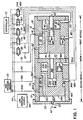
- Figure 1 is a schematic cross section of a modular digital actuator constructed in accordance with the present invention and incorporating a pair of different modules.
- Figure 2 shows a section through a module illustrating an alternative system for preventing overextension of the T shaped piston in either direction.
- digital actuator 10 is formed by a pair of modules 12 and 14 each of which is similarly constructed but may have piston of different cross sectional areas thus the description of module 12 will also be applicable to module 14 and like reference numerals have been used to indicate like parts of the two modules, but with the corresponding parts in the second module 14 followed by the letter A.
- Each module is formed by housings 16 and where the modules are to be assembled in end to end relation it is preferable to make the outside cross section of the housing 16 of each of the modules substantially the same.
- the housings 16 are divided at a line of demarkation 18 into a first cylinder forming section or cavity 20 and a second cylinder forming section or cavity 22.
- a piston 24 is received in the larger cylinder section 20 to form a large area piston on one side thereof and a smaller area piston on the opposite side thereof received in the cavity 25 and is provided on the opposite side thereof with an extension 26 that forms a piston within the second cylinder section 22.
- the piston 24 and extension 25 are integrally interconnected so that movement of one causes movement of the other.
- the extension 26 has a cavity 28 that extends substantially axially thereof and receives a shaft forming piston 30 which is connected to an end closure 32 that closes the end of the housing 16 and thus the end of the small cylinder forming section 22 remote from the larger cylinder forming section 20.
- a first hydraulic flow passage 34 extends through the housing 16 into the section 20 adjacent to the line of demarcation 18 between the cavities 20 and 22, a second hydraulic passage 36 extends through the housing 16 and enters the section 22 at a position adjacent to the end closure 32 and an axial passage 38 extends through the shaft forming piston 30 and end closure 32 into the cavity 28.
- the passage 36 permits the ingress and egress of hydraulic fluid into a cylinder on the outside of the piston 30 and between the end closure 32 and the end wall 40 of the extension 26.
- the passage 34 on the other hand communicates with cylinder formed outside of the extension 26 and permits the development of a hydraulic pressure between the line of demarkation or area of demarkation 18 and the corresponding surface 42 on the first piston 24, i.e. the portion of the piston 24 extended beyond the extension 26.
- the passage 38 permits communication with the cavity 28 and thus adjusts the pressure between the wall 44 of the piston 24 and the end 46 of the piston 30.
- Each of the passages 34, 36 and 38 are connected via line hydraulic 48, 50 and 52 to their respective control valve 54, 56 and 58 respectively.
- the passage 38A in the second module 14 does not have a corresponding line to line 52 since the passage 38A connects directly with the cylinder 20 and transmits the hydraulic pressure within the cylinder 20 into the cavity 28A to thereby couple the two modules together.
- the end of the second module 14 remote from the first module 12 is covered via a cap 58 having a fitting 60 through which hydraulic fluid from the chamber 20A may be withdrawn and directed as indicated by the arrow 62 to actuate any selected hydraulic mechanism.
- Each of the valves 54, 56 and 58 are connected via lines 64 and 66 selectively to a source of hydraulic fluid at low pressure, i.e. a reservoir 68 or to a higher pressure source 70 respectively.
- Each of the valves 54, 56 and 58 are controlled by a controller 72 so that cylinder sections 20, 22, and 28 can be selectively, individually connected either to the high pressure source 70 or the low pressure source 68 via the controller 72.
- the areas of the pistons sections 40, 42 and 44 will be different and will be in a selected sequence.
- the area 44 has been indicated as having an area of 1, the area 42 having an area of 2 which is twice 1 and the area 40 having an area of 4 which is twice the area 2.
- the area 44A has been designated as area 1
- the area 42A is equivalent to the area 44A and the area 40A is twice the area 44A or 42A.
- the passage 74 will connect with the passage 76 which is connected via line 78 to connect the high pressure 70 to the cavity 20 to apply high pressure on the full surface area of the piston 24 and force same to the right.
- the passage 82 communicates with the section 22 to the left of the piston 24 so that the cavity 20 may be connected via line 84 to the low pressure source 68.
- FIG. 2 An alternative system for preventing overextension of the T shaped piston 24 in either direction is shown in Figure 2
- the cylinder 20 is interconnected with the cylinder sections or cavities 22, 28, and 25 respectively by axial passages 100, 102 and 104.
- Each of the passages 100, 102 and 104 has a pair of oppositely biased check valves 106 and 108 which prevent flow through the passages 100, 102 or 104 until the extensions 110 from the balls 106 or the extensions 112 from the balls 108 are forced by contact with an end wall of the cylinder into which they project move the balls 106 or 108 respectively from their seats.
- the rods 106 or 108 depending on the direction of travel will open their respective balls 106 or 108.
- the flow direction in all cases moves the piston 24, 26 toward the centre of travel.
- the three check valve pairs are used because at least one of the cavities 22, 28, 25 must have a higher pressure than the cavity 20 if the piston 24 is to approach the end cap 32A or a pressure less than the cavity 20 if the piston 24, 26 approaches the cap 32.
Landscapes
- Engineering & Computer Science (AREA)
- Mechanical Engineering (AREA)
- General Engineering & Computer Science (AREA)
- Physics & Mathematics (AREA)
- Fluid Mechanics (AREA)
- Actuator (AREA)
Claims (5)
- Modul (12), konstruiert zur Verwendung in einem digitalen Stelltrieb (10), mit einem Gehäuse (16), das ein Paar sich axial erstreckende, Zylinder bildende Teile (20 und 22) aufweist, wobei ein erster Teil (20) des Paars Teile (20 und 22) eine erste Querschnittsfläche aufweist und ein zweiter Teil (22) des Paars Teile (20 und 22) eine zweite Querschnittsfläche aufweist, wobei die erste Querschnittsfläche von der zweiten Querschnittsfläche verschieden ist, und einer Kolbenanordnung (24, 26), worin die Verbesserung umfaßt, daß
die Kolbenanordnung (24, 26) einen ersten Kolben (24) bildet, der in dem ersten Teil (20) axial verschiebbar ist und mit diesem in Eingriff steht, wobei die Kolbenanordnung (24, 26) auch eine Verlängerung (26) einschließt, die einen zweiten Kolben (26) bildet, der mit dem ersten Kolben (24) starr verbunden und in dem zweiten Teil (22) axial verschiebbar ist und in diesen paßt, einen sich axial erstreckenden Hohlraum (28) in der Kolbenanordnung (24, 26), wobei der Hohlraum (28) einen sich in Achsrichtung des Gehäuses (16) erstreckenden Zylinder bildet, einen Schaft (30), der einen dritten Kolben (30) bildet, der sich in Achsrichtung des Gehäuses (16) erstreckt, in dem Hohlraum (28) axial verschiebbar ist und in diesen paßt, einen Endverschluß (32), der das von dem ersten Teil (20) entfernte Ende des zweiten Teils (22) abschließt, wobei der dritte Kolben (30) mit dem Endverschluß (32) verbunden ist, einen axialen Durchgang (38) für einen Fluidstrom zu und von dem Hohlraum (28), der sich durch den Endverschluß (32) und den Schaft (30) erstreckt und in den Hohlraum (28) führt, einen in den ersten Teil (20) führenden ersten Durchgang (34) durch das Gehäuse (16), der einer Trennungslinie (18) zwischen den ersten und zweiten Teilen in dem Gehäuse (16) benachbart ist, für einen Fluidstrom dort hindurch zu und von dem ersten Teil (20) und einen in den zweiten Teil (22) führenden zweiten Durchgang (36) durch das Gehäuse (16), der dem Endverschluß (32) benachbart ist, für einen Fluidstrom zu und von dem zweiten Teil (22) und eine Ventilanordnung (54, 56), die den ersten Durchgang (34) und den zweiten Durchgang (36) mit jeweils entweder einer Niederdruckquelle (68) oder einer Hochdruckquelle (70) eines Fluids wahlweise verbindet. - Modul (12) nach Anspruch 1, ferner mit axial kommunizierenden Durchgängen (100, 102 und 104) durch die Kolbenanordnung (24, 26), die die Zylinderteile (20, 22, 25 und 28) an entgegengesetzten Seiten der Kolbenanordnung (24, 26) miteinander verbinden, einem Paar Ventile (106 und 108) in jedem der kommunizierenden Durchgänge (100, 102 und 104), wobei ein Ventil (106) von jedem Paar Ventile (106, 108) einen Strom durch dessen jeweiligen kommunizierenden Durchgang (100, 102, 104) in eine Richtung verhindert und das andere Ventil (108) von jedem Paar Ventile (106, 108) einen Strom in die andere Richtung durch dessen jeweiligen Durchgang (100, 102, 104) verhindert, und einem Mittel (110), um das eine Ventil (106) des Paars Ventile (106, 108) so zu verstellen, daß es öffnet, wenn sich die Kolbenanordnung zu weit in eine Richtung bewegt, und einem zweiten Mittel (112), um das andere Ventil (108) des Paars Ventile (106, 108) zu verstellen, wenn die Kolbenanordnung (24, 26) zu weit in die der einen Richtung entgegengesetzte Richtung bewegt wird.
- Digitaler Stelltrieb (10), der durch mehrere Module (12, 14) gebildet wird, mit je einem Gehäuse (16), das ein Paar sich axial erstreckende, Zylinder bildende Teile (20 und 22) aufweist, wobei ein erster Teil (20) des Paars Teile (20 und 22) eine erste Querschnittsfläche aufweist und ein zweiter Teil (22) des Paars Teile (20 und 22) eine zweite Querschnittsfläche aufweist, wobei die erste Querschnittsfläche von der zweiten Querschnittsfläche verschieden ist, und einer Kolbenanordnung (24, 26), worin die Verbesserung umfaßt, daß
die Kolbenanordnung (24, 26) einen ersten Kolben (24) bildet, der in dem ersten Teil (20) axial verschiebbar ist und in diesen paßt, wobei die Kolbenanordnung (24, 26) auch eine Verlängerung (26) einschließt, die einen zweiten Kolben (26) bildet, der mit dem ersten Kolben (24) starr verbunden und in dem zweiten Teil (22) axial verschiebbar ist und in diesen paßt, einen sich axial erstreckenden Hohlraum (28) in der Kolbenanordnung (24, 26), wobei der Hohlraum (28) einen sich in Achsrichtung des Gehäuses (16) erstreckenden Zylinder bildet, einen Schaft (30), der einen dritten Kolben (30) bildet, der sich in Achsrichtung des Gehäuses (16) erstreckt und in dem Hohlraum (28) axial verschiebbar ist und in diesen paßt, einen Endverschluß (32), der das von dem ersten Teil (20) entfernte Ende des zweiten Teils (22) abschließt, wobei der dritte Kolben (30) mit dem Endverschluß (32) verbunden ist, einen axialen Durchgang (38) für einen Fluidstrom zu und von dem Hohlraum (28), der sich durch den Endverschluß (32) und den Schaft (30) erstreckt und in den Hohlraum (28) führt, einen in den ersten Teil (20) führenden ersten Durchgang (34) durch das Gehäuse (16), der einer Trennungslinie (18) zwischen den ersten und zweiten Teilen in dem Gehäuse (16) benachbart ist, für einen Fluidstrom dort hindurch zu und von dem ersten Teil (20) und einen in den zweiten Teil (22) führenden zweiten Durchgang (36) durch das Gehäuse (16), der dem Endverschluß (32) benachbart ist, für einen Fluidstrom zu und von dem zweiten Teil (22) und eine Ventilanordnung (54, 56), die den ersten Durchgang (34) und den zweiten Durchgang (36) mit jeweils entweder einer Niederdruckquelle (68) oder einer Hochdruckquelle (70) eines Fluids wahlweise verbindet, wobei die Module (12, 14) axial so angeordnet sind, daß der Endverschluß (32A) eines zweiten Moduls (14) das Ende des zweiten zylinderbildenden Teils (22A) des zweiten Moduls (14) und des ersten zylinderbildenden Teils (20) eines ersten Moduls (12) abschließt, und der axiale Durchgang (38A) in dem zweiten Modul (14) das von dem zweiten Zylinderteil (22) in dem ersten Modul (12) entfernte Ende des ersten Zylinderteils (20) mit dem Hohlraum (28A) in dem zweiten Modul (14) verbindet. - Digitaler Stelltrieb (10) nach Anspruch 3, worin zumindest eine der ersten und zweiten Querschnittsflächen und/oder der Hohlraum (28) in dem ersten Modul (12) eine andere Querschnittsfläche als dessen entsprechende erste Querschnittsfläche, zweite Querschnittsfläche oder entsprechender Hohlraum (28A) in dem zweiten Modul (14) aufweist.
- Digitaler Stelltrieb (10) nach Anspruch 3 oder 4, ferner mit axial kommunizierenden Durchgängen (100, 102 und 104) durch die Kolbenanordnung (24, 26), die die Zylinderteile (20, 22, 25 und 28) an entgegengesetzten Seiten der Kolbenanordnung (24, 26) miteinander verbinden, einem Paar Ventile (106 und 108) in jedem der kommunizierenden Durchgänge (100, 102 und 104), wobei ein Ventil (106) jedes Paars Ventile (106, 108) einen Strom durch dessen jeweiligen kommunizierenden Durchgang (100, 102, 104) in eine Richtung verhindert und das andere Ventil (108) jedes Paars Ventile (106, 108) einen Strom in die andere Richtung durch dessen jeweiligen Durchgang (100, 102, 104) verhindert, und einem Mittel (110), um das eine Ventil (106) des Paars Ventile (106, 108) so zu verstellen, daß es öffnet, wenn sich die Kolbenanordnung zu weit in eine Richtung bewegt, und einem zweiten Mittel (112), um das andere Ventil (108) des Paars Ventile (106, 108) zu verstellen, wenn die Kolbenanordnung (24, 26) zu weit in die der einen Richtung entgegengesetzte Richtung bewegt wird.
Applications Claiming Priority (3)
| Application Number | Priority Date | Filing Date | Title |
|---|---|---|---|
| US756332 | 1991-09-06 | ||
| US07/756,332 US5197285A (en) | 1990-02-02 | 1991-09-06 | Modular digital actuator |
| PCT/CA1992/000372 WO1993005300A1 (en) | 1991-09-06 | 1992-09-01 | Modular digital actuator |
Publications (2)
| Publication Number | Publication Date |
|---|---|
| EP0602085A1 EP0602085A1 (de) | 1994-06-22 |
| EP0602085B1 true EP0602085B1 (de) | 1997-01-08 |
Family
ID=25043014
Family Applications (1)
| Application Number | Title | Priority Date | Filing Date |
|---|---|---|---|
| EP92918154A Expired - Lifetime EP0602085B1 (de) | 1991-09-06 | 1992-09-01 | Modulär aufgebauter digitaler verbraucher |
Country Status (4)
| Country | Link |
|---|---|
| US (1) | US5197285A (de) |
| EP (1) | EP0602085B1 (de) |
| DE (1) | DE69216624T2 (de) |
| WO (1) | WO1993005300A1 (de) |
Families Citing this family (8)
| Publication number | Priority date | Publication date | Assignee | Title |
|---|---|---|---|---|
| US5868317A (en) * | 1997-08-22 | 1999-02-09 | Caterpillar Inc. | Stepped rate shaping fuel injector |
| GB0107607D0 (en) * | 2001-03-27 | 2001-05-16 | Dca Design Int Ltd | Improvements in and relating to an injection device |
| EP1955301A4 (de) * | 2005-11-29 | 2012-08-22 | Elton Daniel Bishop | Digitales hydraulisches system |
| US7669830B2 (en) * | 2006-10-25 | 2010-03-02 | Honeywell International Inc. | Three position shutoff valve |
| US7845575B2 (en) * | 2007-07-16 | 2010-12-07 | Honeywell International Inc. | Temperature-actuated valve assembly |
| US9435446B1 (en) | 2014-07-24 | 2016-09-06 | Google Inc. | Rotary valve with brake mode |
| US9611946B1 (en) * | 2015-08-17 | 2017-04-04 | Google Inc. | Rotary hydraulic valve |
| CN109611305B (zh) * | 2018-12-01 | 2020-02-21 | 东营盛昶石油机械有限公司 | 一种增压水泵 |
Family Cites Families (16)
| Publication number | Priority date | Publication date | Assignee | Title |
|---|---|---|---|---|
| US1142551A (en) * | 1913-04-21 | 1915-06-08 | George W Burnhart | Fluid-pressure motor. |
| US1499569A (en) * | 1921-12-22 | 1924-07-01 | Bailly Armand | Pneumatic hammer |
| US2727467A (en) * | 1951-04-24 | 1955-12-20 | Russell Carl Dexter | Sub-surface pumping units |
| US2862478A (en) * | 1956-06-11 | 1958-12-02 | F E Myers And Bro Company | Fluid motor piston |
| DE1030686B (de) * | 1956-10-18 | 1958-05-22 | Esslingen Maschf | Pneumatisch-hydraulischer Druckerzeuger |
| US3407601A (en) * | 1965-07-26 | 1968-10-29 | Martin Tool Works Inc | Air-hydraulic system and apparatus |
| DE1576163B1 (de) * | 1965-09-16 | 1970-09-10 | Hermann Schleicher | Hydraulisch oder pneumatisch betaetigter Antriebszylinder |
| CH443002A (de) * | 1966-09-07 | 1967-08-31 | Paschke Hanns Dieter | Vorrichtung zur Erzeugung einer oszillierenden Bewegung mit Hilfe eines Druckmediums |
| US3603207A (en) * | 1969-05-26 | 1971-09-07 | Koehring Co | Multiple-cylinder telescopic actuator |
| DE2824181A1 (de) * | 1978-06-02 | 1979-12-06 | Bosch Gmbh Robert | Hydraulikanlage |
| US4505115A (en) * | 1981-09-08 | 1985-03-19 | Arbuckle Donald P | Fluidic transformer apparatus with feedback |
| US4602481A (en) * | 1983-09-26 | 1986-07-29 | The Boeing Company | Fluid actuator for binary selection of output force |
| FR2562963B1 (fr) * | 1984-04-17 | 1986-07-25 | Renault | Amplificateur de pression hydraulique, a surveillance automatique |
| US4922719A (en) * | 1987-10-26 | 1990-05-08 | Arbuckle Donald P | Fluidic transformer with sealed cylinder and check valves in pistons |
| JPH01141905U (de) * | 1988-03-23 | 1989-09-28 | ||
| DE3836103A1 (de) * | 1988-10-22 | 1990-04-26 | Daimler Benz Ag | Hydraulische kolben-zylinder-anordnung |
-
1991
- 1991-09-06 US US07/756,332 patent/US5197285A/en not_active Expired - Fee Related
-
1992
- 1992-09-01 WO PCT/CA1992/000372 patent/WO1993005300A1/en not_active Ceased
- 1992-09-01 DE DE69216624T patent/DE69216624T2/de not_active Expired - Fee Related
- 1992-09-01 EP EP92918154A patent/EP0602085B1/de not_active Expired - Lifetime
Also Published As
| Publication number | Publication date |
|---|---|
| DE69216624T2 (de) | 1997-04-24 |
| EP0602085A1 (de) | 1994-06-22 |
| DE69216624D1 (de) | 1997-02-20 |
| US5197285A (en) | 1993-03-30 |
| WO1993005300A1 (en) | 1993-03-18 |
Similar Documents
| Publication | Publication Date | Title |
|---|---|---|
| CA2242553A1 (en) | Axle tilt control apparatus for industrial vehicles | |
| EP0500162A3 (en) | Poppet valve and valve assemblies utilizing same | |
| EP0602085B1 (de) | Modulär aufgebauter digitaler verbraucher | |
| CA1169742A (en) | Regenerative valve | |
| WO2007118674A2 (de) | Schaltventil | |
| FI72184B (fi) | Fluidumaktiveringsorgan foer stegloes reglering av ventiler | |
| US6220288B1 (en) | Electrohydraulic control device | |
| EP0344714B1 (de) | Flüssigkeitsgesteuerter Betätiger | |
| EP0342410A2 (de) | Sicherheitsventil | |
| US5156189A (en) | High flow control valve | |
| US2804052A (en) | Cushioning structure for hydraulic cylinders | |
| US3605568A (en) | Hydraulic actuator with center lock | |
| USRE24532E (en) | Cushioning structure for hydraulic cylinders | |
| US4716815A (en) | Fluid-pressure-operated actuators | |
| US4903729A (en) | Safety valve | |
| CA1285851C (en) | Electrically controlled hydraulically driven actuator assembly | |
| DE3906528A1 (de) | Hydraulische kupplungseinrichtung, sowie bremsanlage mit einer derartigen kupplung | |
| DE4221088C2 (de) | Aufhängungssystem für Fahrzeuge | |
| US3302922A (en) | Dually effective hydraulic valve | |
| US5058384A (en) | Digital actuator | |
| US5062268A (en) | Fluid actuator | |
| DE3028894A1 (de) | Hydraulische zweikreis-fremdkraftbremse | |
| US4479514A (en) | Float positioning assembly for pilot operated valve | |
| EP0384157B1 (de) | Hydraulisch vorsteuerbares 2-Wege-Einbauventil in Sitzventilbauweise | |
| US4279448A (en) | Brake power control unit for two-circuit brake systems incorporating a locking piston operated hydraulically |
Legal Events
| Date | Code | Title | Description |
|---|---|---|---|
| PUAI | Public reference made under article 153(3) epc to a published international application that has entered the european phase |
Free format text: ORIGINAL CODE: 0009012 |
|
| 17P | Request for examination filed |
Effective date: 19940323 |
|
| AK | Designated contracting states |
Kind code of ref document: A1 Designated state(s): DE |
|
| GRAG | Despatch of communication of intention to grant |
Free format text: ORIGINAL CODE: EPIDOS AGRA |
|
| 17Q | First examination report despatched |
Effective date: 19960326 |
|
| GRAH | Despatch of communication of intention to grant a patent |
Free format text: ORIGINAL CODE: EPIDOS IGRA |
|
| GRAH | Despatch of communication of intention to grant a patent |
Free format text: ORIGINAL CODE: EPIDOS IGRA |
|
| GRAA | (expected) grant |
Free format text: ORIGINAL CODE: 0009210 |
|
| AK | Designated contracting states |
Kind code of ref document: B1 Designated state(s): DE |
|
| REF | Corresponds to: |
Ref document number: 69216624 Country of ref document: DE Date of ref document: 19970220 |
|
| PLBE | No opposition filed within time limit |
Free format text: ORIGINAL CODE: 0009261 |
|
| 26N | No opposition filed | ||
| PGFP | Annual fee paid to national office [announced via postgrant information from national office to epo] |
Ref country code: DE Payment date: 19980930 Year of fee payment: 7 |
|
| PG25 | Lapsed in a contracting state [announced via postgrant information from national office to epo] |
Ref country code: DE Free format text: LAPSE BECAUSE OF NON-PAYMENT OF DUE FEES Effective date: 20000701 |