EP0602119B2 - Appareil et procede de detection photoacoustique de fuite - Google Patents
Appareil et procede de detection photoacoustique de fuite Download PDFInfo
- Publication number
- EP0602119B2 EP0602119B2 EP92918578A EP92918578A EP0602119B2 EP 0602119 B2 EP0602119 B2 EP 0602119B2 EP 92918578 A EP92918578 A EP 92918578A EP 92918578 A EP92918578 A EP 92918578A EP 0602119 B2 EP0602119 B2 EP 0602119B2
- Authority
- EP
- European Patent Office
- Prior art keywords
- leak
- gas
- component
- light beam
- scan
- Prior art date
- Legal status (The legal status is an assumption and is not a legal conclusion. Google has not performed a legal analysis and makes no representation as to the accuracy of the status listed.)
- Expired - Lifetime
Links
Images

Classifications
-
- G—PHYSICS
- G01—MEASURING; TESTING
- G01M—TESTING STATIC OR DYNAMIC BALANCE OF MACHINES OR STRUCTURES; TESTING OF STRUCTURES OR APPARATUS, NOT OTHERWISE PROVIDED FOR
- G01M3/00—Investigating fluid-tightness of structures
- G01M3/38—Investigating fluid-tightness of structures by using light
-
- G—PHYSICS
- G01—MEASURING; TESTING
- G01M—TESTING STATIC OR DYNAMIC BALANCE OF MACHINES OR STRUCTURES; TESTING OF STRUCTURES OR APPARATUS, NOT OTHERWISE PROVIDED FOR
- G01M3/00—Investigating fluid-tightness of structures
- G01M3/02—Investigating fluid-tightness of structures by using fluid or vacuum
- G01M3/04—Investigating fluid-tightness of structures by using fluid or vacuum by detecting the presence of fluid at the leakage point
- G01M3/24—Investigating fluid-tightness of structures by using fluid or vacuum by detecting the presence of fluid at the leakage point using infrasonic, sonic or ultrasonic vibrations
Definitions
- the present invention relates to gas leak alarm generally, and, more specifically, the inventior is directed to an apparatus and method for leak-checking of gas or liquid-tight components on the production line or in the field.
- the pressure-hold method is essentially a yes/no leak-tight test in that it only indicates to the operator whether or not the unit has a leak - it does not tell him the leak location. Furthermore, for large components with small leaks, a lengthy time period is required The procedure is also affected by any temperature changes which may occur during the monitoring period.
- a more sensitive technique involves drawing a vacuum on the component and then completely surrounding it with helium gas.
- a detector inside the vacuum system notifies the operator if helium is present in the air being pumped from the component.
- This technique is capable of detecting leaks as small as 10 -9 standard cubic centimeters/second (scc/sec), but is very expensive to set-up and to maintain, and as with the pressure-decay technique, does not indicate the location of the leak.
- the pressurization/immersion technique consists of pressurizing the component, totally immersing it in water or some other clear liquid, and observing the point of bubble emergence. This technique works quite nicely in situations involving small components which are not adversely affected by liquid immersion. However, the technique usually requires some post-test clean-up and/or drying procedure. This technique is capable of locating leaks as small as 10 -4 scc/sec with proper lighting, use of low surface tension liquids, and if adequate viewing time is allowed. It is a very labor intensive, time consuming method which requires extreme worker concentration for long periods of time. It is a leak location technique which does not very easily lend itself to automation.
- Pressurization/soaping is another leak location technique which is generally used to locate leaks from components or larger complex systems where total immersion is not practical.
- the leaky component is pressurized with air, painted or sprayed with a thin viscous liquid (usually soap), and observed for the presence of bubbles which indicate the leak location
- a thin viscous liquid usually soap
- This technique requires that the liquid soap be placed on the leak, and observed for bubble formation before it either evaporates or flows away.
- Experienced technicians say they can locate leaks as small as 10 -3 scc/sec with this technique, making it about 10 times less sensitive than the pressurization/submersion technique.
- the component With the pressurization/ammonia-sensitive painting technique, the component is coated with a water soluble, ammonia-sensitive paint, a small amount of liquid ammonia is injected into the component, it is sealed and pressurized with air.
- the ammonia/air mixture emerging from the leak produces a discoloring of the special paint thus pin-pointing the location of the leak.
- This technique is quite expensive, involves the use of a toxic material (ammonia), and requires extensive post-test clean-up. However, it offers complete coverage of the component and is quite sensitive.
- an observer can see paint discoloration within one minute at a distance of 5 meters produced by a 10 ⁇ m diameter pinhole leak pressurized to 1.3 atmospheres. Under the same conditions, a 30 ⁇ m pinhole leak will produce a 6 mm diameter discoloration within one minute.
- These leak rates are estimated to be in the 10 -3 scc/sec range.
- the tracer gas injection/detection technique involves pressurizing the component with a tracer gas. usually helium (He) or a chlorofluorocarbon (CFC), and surveying the exterior with a sensitive sniffer-type detector.
- a tracer gas usually helium (He) or a chlorofluorocarbon (CFC)
- CFC chlorofluorocarbon
- This technique is extremely sensitive, capable of locating leaks as small as 10 -6 scc/sec if the intake of the sniffer is placed directly over the source of the leak.
- Drawbacks to the He approach are the cost of the gas and the detection system: however, this technique is relatively free of background gas false readings.
- the cost of the CFC gas and detectors is quite reasonable, but these sniffers are affected by a host of common background gases, and are currently being phased out as tracer gases due to their adverse affect on the environment. Also with this technique, location of small leaks can be masked by the presence of a large leak located nearby.
- the instant invention involves a physical process commonly known as the photo-acoustic effect, which is used in various forms as a gas detection technique.
- U. S. Pat. No. 4,516,858 to Gelbwachs describes an apparatus in which a laser beam is distributed to a number of photo-acoustic cells via fiber optic cables for the purpose of monitoring hazardous gas concentrations at multiple sites.
- U. S. Pat. No. 4,557,603 to Oehler et al. discloses an apparatus for the selective detection of a variety of gases using the photo-acoustic effect.
- a monochromator is used to vary the wavelength of the light introduced to a photo-acoustic cell containing the gas to be analyzed.
- U. S. Pat. No. 4,622,845 to Ryan, et al. discloses an apparatus using a pulsed infrared light source and an acousto-optic tuneable filter to provide illumination of a photo-acoustic cell containing a gas sample extracted from the environment.
- the gas to be detected must be introduced into a photo-acoustic cell which is then irradiated with pulsed or modulated light which is spectrally selected to be strongly absorbed by the gas within the cell.
- the purpose of all of the above mentioned inventions is for concentration measurements of the gases of interest. Futher US-A-4 457 162, which describes gas analysis device including a photoacoustic cell, does specifically mention application to leak detection in natural gas systems. No further detail is provided.
- the invention provides a process and an apparatus for the detection of leaks which may exist in supposedly gas-tight or liquid-tight components and/or systems.
- the invention is based on the photo-acoustic effect which occurs when a gas absorbs light. When the wavelength of the light coincides with an absorption line of the gas, the energy absorbed produces temperature and pressure increases in the gas. If the energy absorbed is of sufficient magnitude, a pressure, or acoustic, wave is generated which may be detected by a pressure transducer, such as a microphone.
- the invention is comprised of a continuous-wave laser beam, or other well collimated beam of light, which is scanned across the component to be leak tested. The component under test is pressurized with a gas which strongly absorbs the scanned light beam.
- the emerging gas absorbs the light as it passes through it, and produces an acoustic emission which is then detected by a microphone or similar detector.
- the resulting signal may then be used to notify the operator that a leak is present.
- the scanning of the light beam across the component under test is in a repeatable or controlled pattern, the resulting acoustic signal can be used to indicate the location of the leak on the component.
- Still another object of the invention is to provide a method and apparatus for the detection of leaks by scanning the component under test with a collimated beam of light and detecting a resulting acoustic signal.
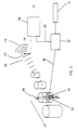
- Fig. 1 shows the primary components, of a photo-acoustic leak location/alarm (PALLA) system of the invention.
- Fig. 2 is a diagram of a one-dimensional PALLA system of the invention.
- PALLA photo-acoustic leak location/alarm
- the invention is a method and apparatus for detecting the presence of a gas leak.
- the invention comprises a collimated light source 11 and a beam scanning mechanism 12 which irradiates the leaking component 13 and an acoustic detection system 14 to detect the acoustic waves generated by the leaking gas 15 upon absorption of the light beam 16.
- the resulting signal may be used to notify the operator that the component has a leak, or if coordinated with the light beam scanning pattern, may be used to determine the location of the leak on the component 13 under test.
- FIG. 1 A block diagram showing the major components of a PALLA system is shown in Fig. 1.
- a collimated light beam 16 such as a laser beam, is scanned across the component 13 under test by a beam scanning mechanism 12.
- the component 13 has been injected with a tracer gas 17 which strongly absorbs the wavelength of the light beam 16. If the component 13 has a leak, the leaking gas 15 will absorb the scanned light as it passes through the gas 15. The absorption of the light energy results in a momentary and local pressure disturbance within the leaking gas 15 which propagates away in all directions, generally as an acoustic emission 19.
- the frequency(s) of this acoustic emission 19 will depend on the frequency(s) of irradiation of the leaking gas 15 by the scanning light beam 16.
- This acoustic emission 19 is detected by an acoustic detection system 14 and processed by a signal processing unit 20.
- the resulting leak indication signal 21 may then be used as an alarm to notify the operator that the component 13 has a leak, and/or to aid the operator in locating the source of the leak.
- Fig. 1 shows a two-dimensional scanning PALLA system which may be used for either leak alarm or leak location situations.
- a collimated light source 11 for example, the light beam from a CO 2 laser operating at a wavelength of 10.5514 microns, is introduced to a raster scan mechanism 12.
- the beam scanning may be accomplished by any number of standard techniques such as a two-axis scan mirror arrangement, a two-axis rotating polygon arrangement, holographic scanners, acousto-optic scanners, electro-optic scanners, pan and tilt mountings, or combinations thereof.
- the component 13 under test is positioned so as to be fully enveloped by the total 2-dimensional scan field-of-view 18, or so as to pass through the total scan field-of-view 18.
- the component 13 is pressurized with a tracer gas 17, such as sulfur hexafluoride (SF 6 ), which strongly absorbs the 10.5514 micron light. If a leak is present, the acoustic emission produced by the absorption of the laser light 16 by the SF 6 gas 15, is detected by a directional shot-gun microphone or sensitive microphone 22 and parabolic reflector 23 arrangement which is aimed at the component 13 under test.
- the signal from the microphone 22, along with scan positioning signals 26 from the beam scanning mechanism 12, are submitted to the signal processing unit 20. Careful attention must be paid so as to eliminate background acoustical noise, so use of the beam scan frequency and position signals 26 in the signal processing unit 20 is essential.
- Standard practices for extracting the acoustic emission 19 from the background acoustic noise(s), such as tuned microphones, acoustical filtering, lock-in detection and amplification, digital signal processing, or combinations thereof, are used in the signal processing unit 20 to generate the appropriate leak indication signal 21.
- Fig. 1 In its simplest application, the embodiment of Fig. 1 would be used as a leak alarm system, in which the exact location of the leak within the total scan field-of-view 18 is not required. However, due to the two-dimensional nature of the beam raster scan pattem 25, the exact location of the leak can also be determined by a number of different techniques.
- the simplest leak location technique consists of manually blocking, or shadowing, the light beam irradiation of the component by positioning a small area disc between the PALLA system and the component. As this blocking disk is passed over the component 13, it interrupts the light beam from irradiating a small area on the component 13.
- the acoustic emission 19 will still be detected. However, as the disk is positioned so as to block the light beam 16 irradiation of that region within the beam raster scan pattern 25 where the leaking gas 15 is present, the acoustic emission 19 will cease, notifying the operator that he has successfully pinpointed the leak source.
- This same leak location technique ie, local shadowing of the component 13 under test, may also be accomplished internal to the PALLA system by systematically modulating or chopping the light beam 16 at different positions of the beam raster scan pattern 25 while simultaneously noting the acoustic emission signal 19. In this manner, the horizontal and vertical position within the total scan field-of-view 18 corresponding to the reduction, or loss, of the acoustic signal indicates the location of the leak.
- a second relatively simple method of determining the location of a leak within the total scan field-of-view 18 would be to temporarily reduce the scan area, or zoom-in the field-of-view, and then manually or automatically direct this reduced scan area to various points on the component under test until the acoustic emission signal 19 is maximized.
- FIG. 2 shows a one-dimensional version of the PALLA system which may also be used as a leak alarm system.
- the collimated light beam 11 is scanned by a scanning mechanism 12 in one direction only, ie, a one-dimensional line scan pattern 29, while cross-wise motion of the component 13 under test, which has been pressurized with the tracer gas 17, provides complete coverage for leak detection purposes.
- processing of the acoustic emission signal 19 can be such as to allow for the simple alarm mode of operation, or correlated with the line scan position signal 26 and component 13 cross-wise movement to provide leak information.
Landscapes
- Physics & Mathematics (AREA)
- General Physics & Mathematics (AREA)
- Examining Or Testing Airtightness (AREA)
- Investigating Or Analyzing Materials By The Use Of Ultrasonic Waves (AREA)
Claims (9)
- Appareil de détection rapide d'une fuite de gaz sortant d'un composant étanche au gaz ou étanche au liquide (13), soumis à un test, comprenant :une source de lumière (11) pour fournir un faisceau de lumière collimaté continu (16) à une longueur d'onde fortement absorbée par le gaz de fuite ;des moyens de balayage de faisceau (12) alignés optiquement avec la source de lumière pour balayer le faisceau de lumière à travers le composant en cours de test à une fréquence de balayage de faisceau dans une configuration prédéterminée, et pour fournir un signal de sortie de positionnement de balayage ;des moyens de détection acoustiques (14) pour détecter des ondes acoustiques générées par la fuite de gaz au moment de l'absorption du faisceau de lumière et pour produire un signal électrique proportionnel à l'émission acoustique, et ;des moyens de traitement de signal (20) branchés aux moyens de balayage de faisceau (12) et aux moyens de détection acoustiques (14) traitant les ondes acoustiques réfléchis par rapport à la fréquence de balayage de faisceau et aux signaux de position de balayage, pour extraire les émissions acoustiques de fuite de gaz des émissions acoustiques de bruit de fond, et pour générer un signal d'indication de fuite.
- Appareil selon la revendication 1,
caractérisé en ce que
la longueur d'onde est une longueur d'onde d'absorption de l'hexafluorure de soufre qui, pendant l'utilisation de l'appareil, est injecté dans le composant soumis au test. - Appareil selon la revendication 1,
caractérisé en ce que
la source de lumière consiste en un laser. - Appareil selon la revendication 3,
caractérisé en ce que le laser consiste en un laser à CO2 fonctionnant à une longueur d'onde de 10,5514 micromètres. - Appareil selon la revendication 1,
caractérisé en ce que
le composant soumis au test est positionné pour être irradié par un balayage en deux dimensions, de type tramé, du faisceau de lumière. - Appareil selon la revendication 1,
caractérisé en ce que
le composant en cours de test est positionné pour être balayé par le faisceau de lumière dans une seule dimension, tandis qu'un mouvement dans le sens transversal du composant permet d'obtenir une couverture complète pour la détection de fuite. - Procédé de détection d'une fuite de gaz sortant d'un composant étanche au gaz ou étanche au liquide, soumis au test, comprenant les étapes consistant à :injecter un gaz traceur dans le composant soumis au test ;produire le balayage continu d'un faisceau de lumière collimaté, à une longueur d'onde fortement absorbée par le gaz traceur, en travers du composant, à une fréquence de balayage de faisceau, dans une configuration prédéterminée, et générer un signal de position de balayage indiquant l'emplacement du faisceau de lumière dans un champ de vision prédéterminé ;détecter des émissions acoustiques générées par le gaz traceur au moment de l'absorption du faisceau de lumière ; ettraiter les ondes acoustiques détectées en relation avec la fréquence de balayage de faisceau et les signaux de position de balayage, et fournir des signaux d'indication de fuite pour indiquer l'existence d'une fuite.
- Procédé selon la revendication 7,
caractérisé en ce que
la configuration prédéterminée consiste en une configuration de balayage en deux dimensions du faisceau de lumière. - Procédé selon la revendication 7,
caractérisé en ce que
la configuration prédéterminée consiste en un mouvement dans le sens transversal du composant, et un balayage en une seule dimension effectué par le faisceau de lumière.
Applications Claiming Priority (3)
| Application Number | Priority Date | Filing Date | Title |
|---|---|---|---|
| US749910 | 1991-08-26 | ||
| US07/749,910 US5161408A (en) | 1991-08-26 | 1991-08-26 | Photo-acoustic leak detection system and method |
| PCT/US1992/006949 WO1993004352A1 (fr) | 1991-08-26 | 1992-08-20 | Appareil et procede de detection photoacoustique de fuite |
Publications (4)
| Publication Number | Publication Date |
|---|---|
| EP0602119A1 EP0602119A1 (fr) | 1994-06-22 |
| EP0602119A4 EP0602119A4 (en) | 1994-06-29 |
| EP0602119B1 EP0602119B1 (fr) | 1996-06-05 |
| EP0602119B2 true EP0602119B2 (fr) | 1999-04-07 |
Family
ID=25015727
Family Applications (1)
| Application Number | Title | Priority Date | Filing Date |
|---|---|---|---|
| EP92918578A Expired - Lifetime EP0602119B2 (fr) | 1991-08-26 | 1992-08-20 | Appareil et procede de detection photoacoustique de fuite |
Country Status (7)
| Country | Link |
|---|---|
| US (1) | US5161408A (fr) |
| EP (1) | EP0602119B2 (fr) |
| JP (1) | JP3040474B2 (fr) |
| AT (1) | ATE139029T1 (fr) |
| CA (1) | CA2116345C (fr) |
| DE (1) | DE69211350T3 (fr) |
| WO (1) | WO1993004352A1 (fr) |
Families Citing this family (50)
| Publication number | Priority date | Publication date | Assignee | Title |
|---|---|---|---|---|
| EP0552044B1 (fr) * | 1992-01-16 | 1996-10-09 | Kabushiki Kaisha Toshiba | Procédé et appareil de détection de la position d'un site anormal d'une conduite enterrée |
| US5576480A (en) * | 1992-11-06 | 1996-11-19 | Pall Corporation | System and method for testing the integrity of porous elements |
| US5417113A (en) * | 1993-08-18 | 1995-05-23 | The United States Of America As Represented By The Administrator Of The National Aeronautics And Space Administration | Leak detection utilizing analog binaural (VLSI) techniques |
| EP0640822B1 (fr) * | 1993-08-30 | 1998-04-22 | Millipore Investment Holdings Limited | Essai d'intégrité de structures poreuses utilisant l'émission acoustique |
| DE4415852A1 (de) * | 1994-05-05 | 1995-11-09 | Gerhart Schroff | Verfahren und Anordnung zur Dichtheitsprüfung |
| US5917193A (en) * | 1995-01-14 | 1999-06-29 | Schroff; Gerhart | Method and apparatus for detecting leaks in a container |
| JPH09304281A (ja) * | 1996-05-09 | 1997-11-28 | Tokyo Electric Power Co Inc:The | 油検知装置 |
| US5854422A (en) * | 1996-07-10 | 1998-12-29 | K-Line Industries, Inc. | Ultrasonic detector |
| US5834632A (en) * | 1997-03-27 | 1998-11-10 | United Technologies Corporation | Photo-acoustic leak detector with multiple beams |
| US5780724A (en) * | 1997-03-27 | 1998-07-14 | United Technologies Corp | Photo-acoustic leak detector with improved signal-to-noise response |
| US5979239A (en) * | 1997-04-28 | 1999-11-09 | The United States Of America As Represented By The Administrator Of The National Aeronautics And Space Administration | Ultrasonic imaging system |
| US6157033A (en) * | 1998-05-18 | 2000-12-05 | Power Distribution Services, Inc. | Leak detection system |
| US6154307A (en) * | 1998-09-18 | 2000-11-28 | United Technologies Corporation | Method and apparatus to diffract multiple beams |
| US6089076A (en) * | 1998-09-18 | 2000-07-18 | United Technologies Corporation | System to control the power of a beam |
| US6227036B1 (en) | 1998-10-28 | 2001-05-08 | The Regents Of The University Of Michigan | Multiple microphone photoacoustic leak detection and localization system and method |
| FR2786566B1 (fr) * | 1998-11-26 | 2000-12-29 | Cit Alcatel | Procede et dispositif de detection de fuites sur echangeurs automobiles |
| GB0015691D0 (en) * | 2000-06-28 | 2000-08-16 | Bae Systems Plc | Detection of fuel leak sites in aricraft |
| US6553809B1 (en) | 2001-11-01 | 2003-04-29 | Plastic Technologies, Inc. | Method and apparatus for detecting holes in plastic containers |
| US6866089B2 (en) * | 2002-07-02 | 2005-03-15 | Carrier Corporation | Leak detection with thermal imaging |
| US20040016700A1 (en) * | 2002-07-23 | 2004-01-29 | Benjamin Kellam | System and a method for determining integrity of a dialyzer |
| US7375814B2 (en) * | 2005-03-11 | 2008-05-20 | Sandia Corporation | Natural gas leak mapper |
| US7535656B2 (en) | 2005-06-15 | 2009-05-19 | Daylight Solutions, Inc. | Lenses, optical sources, and their couplings |
| US7492806B2 (en) | 2005-06-15 | 2009-02-17 | Daylight Solutions, Inc. | Compact mid-IR laser |
| US7644606B2 (en) * | 2007-01-29 | 2010-01-12 | Uchicago Argonne, Llc | Photoacoustic spectroscopy system and technique for remote sensing of explosives and toxic chemicals |
| US8653461B1 (en) | 2007-03-23 | 2014-02-18 | Flir Systems, Inc. | Thermography camera tuned to detect absorption of infrared radiation in a selected spectral bandwidth |
| US8659664B2 (en) | 2007-03-23 | 2014-02-25 | Flir Systems, Inc. | Thermography camera configured for leak detection |
| US20090159798A1 (en) * | 2007-12-20 | 2009-06-25 | Daylight Solutions, Inc. | Gas imaging system |
| US7848382B2 (en) | 2008-01-17 | 2010-12-07 | Daylight Solutions, Inc. | Laser source that generates a plurality of alternative wavelength output beams |
| US8468874B2 (en) * | 2008-02-06 | 2013-06-25 | Radiaulics, Inc. | Laser indicator for remote measuring devices and methods therefor |
| WO2009117399A2 (fr) * | 2008-03-17 | 2009-09-24 | Plastic Technologies, Inc. | Procédé et appareil pour la détection améliorée de trous dans des contenants en plastique |
| US20100110198A1 (en) * | 2008-04-01 | 2010-05-06 | Daylight Solutions, Inc. | Mid infrared optical illuminator assembly |
| US8306077B2 (en) | 2008-04-29 | 2012-11-06 | Daylight Solutions, Inc. | High output, mid infrared laser source assembly |
| US8565275B2 (en) | 2008-04-29 | 2013-10-22 | Daylight Solutions, Inc. | Multi-wavelength high output laser source assembly with precision output beam |
| DE102008057458B4 (de) * | 2008-11-14 | 2012-04-26 | Sartorius Stedim Biotech Gmbh | Verfahren und Vorrichtung zur Durchführung von Integritätstests |
| US8774244B2 (en) | 2009-04-21 | 2014-07-08 | Daylight Solutions, Inc. | Thermal pointer |
| US20110080311A1 (en) * | 2009-10-05 | 2011-04-07 | Michael Pushkarsky | High output laser source assembly with precision output beam |
| US8718105B2 (en) | 2010-03-15 | 2014-05-06 | Daylight Solutions, Inc. | Laser source that generates a rapidly changing output beam |
| US8335413B2 (en) | 2010-05-14 | 2012-12-18 | Daylight Solutions, Inc. | Optical switch |
| US8467430B2 (en) | 2010-09-23 | 2013-06-18 | Daylight Solutions, Inc. | Continuous wavelength tunable laser source with optimum orientation of grating and gain medium |
| US9225148B2 (en) | 2010-09-23 | 2015-12-29 | Daylight Solutions, Inc. | Laser source assembly with thermal control and mechanically stable mounting |
| US9042688B2 (en) | 2011-01-26 | 2015-05-26 | Daylight Solutions, Inc. | Multiple port, multiple state optical switch |
| ES2588832T3 (es) * | 2012-04-16 | 2016-11-07 | Vestas Wind Systems A/S | Método de fabricación de una pieza de material compuesto y aparato para la fabricación de una pieza de material compuesto |
| JP5936529B2 (ja) * | 2012-12-14 | 2016-06-22 | 三菱重工業株式会社 | ガス漏洩検知システム |
| CN103439060A (zh) * | 2013-08-27 | 2013-12-11 | 南京诺威尔光电系统有限公司 | 激光同步扫描成像微量气体检测方法及系统 |
| US9939343B2 (en) * | 2014-09-30 | 2018-04-10 | Uchicago Argonne, Llc | Acoustic building infiltration measurement system |
| US9541537B1 (en) * | 2015-09-24 | 2017-01-10 | Frito-Lay North America, Inc. | Quantitative texture measurement apparatus and method |
| US11243190B2 (en) | 2015-09-24 | 2022-02-08 | Frito-Lay North America, Inc. | Quantitative liquid texture measurement method |
| US20160205810A1 (en) * | 2016-03-21 | 2016-07-14 | Sam A Marshall | Inherently leak free liquid cooling of equipment |
| CN114832517B (zh) * | 2022-06-17 | 2024-03-22 | 河南工小艺物联科技有限公司 | 一种带破袋定位功能的脉冲控制系统 |
| CN116878741B (zh) * | 2023-09-06 | 2023-12-01 | 江苏炎启自动化有限公司 | 一种用于gis室内气体泄漏的检测装置及其使用方法 |
Family Cites Families (8)
| Publication number | Priority date | Publication date | Assignee | Title |
|---|---|---|---|---|
| CA1007325A (en) * | 1973-11-14 | 1977-03-22 | Her Majesty In Right Of Canada As Represented By Atomic Energy Of Canada Limited | Gas detection system |
| SU868389A1 (ru) * | 1980-01-02 | 1981-09-30 | Предприятие П/Я А-3503 | Устройство дл контрол герметичности |
| US4516858A (en) | 1982-02-09 | 1985-05-14 | The United States Of America As Represented By The Secretary Of The Air Force | Multiple site laser excited pollution monitoring system |
| US4457162A (en) * | 1982-09-17 | 1984-07-03 | Institute Of Gas Technology | Multi-frequency photo-acoustic detector |
| US4555627A (en) * | 1983-04-05 | 1985-11-26 | The United States Of America As Represented By The United States Department Of Energy | Backscatter absorption gas imaging system |
| SU1281947A1 (ru) * | 1984-12-19 | 1987-01-07 | Организация П/Я М-5222 | Устройство дл контрол герметичности заполн емых контрольным газом изделий |
| US4622845A (en) | 1985-03-21 | 1986-11-18 | Westinghouse Electric Corp. | Method and apparatus for the detection and measurement of gases |
| US4772789A (en) * | 1987-12-28 | 1988-09-20 | Rockwell International Corporation | Leak imaging using differential absorption |
-
1991
- 1991-08-26 US US07/749,910 patent/US5161408A/en not_active Expired - Fee Related
-
1992
- 1992-08-20 EP EP92918578A patent/EP0602119B2/fr not_active Expired - Lifetime
- 1992-08-20 AT AT92918578T patent/ATE139029T1/de not_active IP Right Cessation
- 1992-08-20 CA CA002116345A patent/CA2116345C/fr not_active Expired - Fee Related
- 1992-08-20 DE DE69211350T patent/DE69211350T3/de not_active Expired - Fee Related
- 1992-08-20 WO PCT/US1992/006949 patent/WO1993004352A1/fr not_active Ceased
- 1992-08-20 JP JP5504540A patent/JP3040474B2/ja not_active Expired - Fee Related
Non-Patent Citations (3)
| Title |
|---|
| Chemical Processing,Aug.1989,pp.40-44; A.Sobel:"Locating leaks with lasers" † |
| J.Phys.D:Appl.Phys.,vol.15, 1982, pp219-228; D.J.Brassington: "Photo-acoustic detection and ranging - a new technique for the remote detection of gases" † |
| Material Evaluation,vor.47,Nov.1989, pp.1308-1312; T.G.McRae:"Remote Sensing Technique for Leak Testing of Components and Systems" † |
Also Published As
| Publication number | Publication date |
|---|---|
| ATE139029T1 (de) | 1996-06-15 |
| EP0602119A1 (fr) | 1994-06-22 |
| JPH06510121A (ja) | 1994-11-10 |
| DE69211350T3 (de) | 1999-07-22 |
| WO1993004352A1 (fr) | 1993-03-04 |
| EP0602119A4 (en) | 1994-06-29 |
| DE69211350D1 (de) | 1996-07-11 |
| DE69211350T2 (de) | 1997-01-16 |
| CA2116345A1 (fr) | 1993-03-04 |
| US5161408A (en) | 1992-11-10 |
| JP3040474B2 (ja) | 2000-05-15 |
| CA2116345C (fr) | 1999-06-01 |
| EP0602119B1 (fr) | 1996-06-05 |
Similar Documents
| Publication | Publication Date | Title |
|---|---|---|
| EP0602119B1 (fr) | Appareil et procede de detection photoacoustique de fuite | |
| US6227036B1 (en) | Multiple microphone photoacoustic leak detection and localization system and method | |
| US5780724A (en) | Photo-acoustic leak detector with improved signal-to-noise response | |
| US3925666A (en) | Gas detection system | |
| US5163315A (en) | Leak detecting method for vessels | |
| US3838593A (en) | Acoustic leak location and detection system | |
| US6041020A (en) | Gas-coupled laser acoustic detection | |
| US4612797A (en) | Leak locating and mapping system and method | |
| EP0970359A1 (fr) | Detecteur de fuites photo-acoustique a faisceaux multiples | |
| US4516858A (en) | Multiple site laser excited pollution monitoring system | |
| CN108107017A (zh) | 基于太赫兹探测高危化学品分布的方法 | |
| EP0060629A1 (fr) | Surveillance de gaz nuisible par laser | |
| JP3538516B2 (ja) | 濃度分布計測装置 | |
| Huang et al. | High-sensitivity photoacoustic leak testing | |
| EP0566862A1 (fr) | Méthode et dispositif pour détecter des barreaux combustibles faillis par utilisation d'une atténuation de l'énergie d'ondes acoustiques | |
| Yönak et al. | Parametric dependencies for photoacoustic leak localization | |
| US5790617A (en) | Method and apparatus for detection of failed fuel rods by use of acoustic energy frequency attenuation | |
| CN107843573A (zh) | 大气高危化学品探测的太赫兹自反馈系统 | |
| Martinsen et al. | Optical measurements of ripples using a scanning-laser slope gauge: Part I--instrumentation and preliminary results | |
| Moon et al. | Ultrasound techniques for leak detection in vehicle and pressure vessel production lines | |
| CN105548041A (zh) | 一种气体泄漏的检测装置及方法 | |
| US12228548B2 (en) | Coating inspection using steady-state excitation | |
| CN108169160A (zh) | 基于太赫兹的单个大气高危化学品泄漏源探测方法 | |
| CA1133276A (fr) | Appareil de balayage a laser | |
| CN105548042A (zh) | 气体泄漏的检测装置及方法 |
Legal Events
| Date | Code | Title | Description |
|---|---|---|---|
| PUAI | Public reference made under article 153(3) epc to a published international application that has entered the european phase |
Free format text: ORIGINAL CODE: 0009012 |
|
| 17P | Request for examination filed |
Effective date: 19940308 |
|
| AK | Designated contracting states |
Kind code of ref document: A1 Designated state(s): AT BE CH DE DK ES FR GB GR IE IT LI LU MC NL SE |
|
| A4 | Supplementary search report drawn up and despatched |
Effective date: 19940509 |
|
| AK | Designated contracting states |
Kind code of ref document: A4 Designated state(s): AT BE CH DE DK ES FR GB GR IE IT LI LU MC NL SE |
|
| RIN1 | Information on inventor provided before grant (corrected) |
Inventor name: DEWEY, ALAN H. Inventor name: MCRAE, THOMAS |
|
| RAP1 | Party data changed (applicant data changed or rights of an application transferred) |
Owner name: LASER IMAGING SYSTEMS |
|
| 17Q | First examination report despatched |
Effective date: 19950908 |
|
| GRAH | Despatch of communication of intention to grant a patent |
Free format text: ORIGINAL CODE: EPIDOS IGRA |
|
| GRAA | (expected) grant |
Free format text: ORIGINAL CODE: 0009210 |
|
| AK | Designated contracting states |
Kind code of ref document: B1 Designated state(s): AT BE CH DE DK ES FR GB GR IE IT LI LU MC NL SE |
|
| PG25 | Lapsed in a contracting state [announced via postgrant information from national office to epo] |
Ref country code: NL Free format text: LAPSE BECAUSE OF FAILURE TO SUBMIT A TRANSLATION OF THE DESCRIPTION OR TO PAY THE FEE WITHIN THE PRESCRIBED TIME-LIMIT Effective date: 19960605 Ref country code: LI Free format text: LAPSE BECAUSE OF FAILURE TO SUBMIT A TRANSLATION OF THE DESCRIPTION OR TO PAY THE FEE WITHIN THE PRESCRIBED TIME-LIMIT Effective date: 19960605 Ref country code: GR Free format text: LAPSE BECAUSE OF FAILURE TO SUBMIT A TRANSLATION OF THE DESCRIPTION OR TO PAY THE FEE WITHIN THE PRESCRIBED TIME-LIMIT Effective date: 19960605 Ref country code: ES Free format text: THE PATENT HAS BEEN ANNULLED BY A DECISION OF A NATIONAL AUTHORITY Effective date: 19960605 Ref country code: DK Effective date: 19960605 Ref country code: CH Free format text: LAPSE BECAUSE OF FAILURE TO SUBMIT A TRANSLATION OF THE DESCRIPTION OR TO PAY THE FEE WITHIN THE PRESCRIBED TIME-LIMIT Effective date: 19960605 Ref country code: BE Effective date: 19960605 Ref country code: AT Effective date: 19960605 |
|
| REF | Corresponds to: |
Ref document number: 139029 Country of ref document: AT Date of ref document: 19960615 Kind code of ref document: T |
|
| REG | Reference to a national code |
Ref country code: IE Ref legal event code: FG4D Free format text: 68641 |
|
| REF | Corresponds to: |
Ref document number: 69211350 Country of ref document: DE Date of ref document: 19960711 |
|
| PG25 | Lapsed in a contracting state [announced via postgrant information from national office to epo] |
Ref country code: IE Free format text: LAPSE BECAUSE OF NON-PAYMENT OF DUE FEES Effective date: 19960820 |
|
| ITF | It: translation for a ep patent filed | ||
| PG25 | Lapsed in a contracting state [announced via postgrant information from national office to epo] |
Ref country code: LU Free format text: LAPSE BECAUSE OF NON-PAYMENT OF DUE FEES Effective date: 19960831 |
|
| PG25 | Lapsed in a contracting state [announced via postgrant information from national office to epo] |
Ref country code: SE Effective date: 19960905 |
|
| ET | Fr: translation filed | ||
| NLV1 | Nl: lapsed or annulled due to failure to fulfill the requirements of art. 29p and 29m of the patents act | ||
| REG | Reference to a national code |
Ref country code: CH Ref legal event code: PL |
|
| PG25 | Lapsed in a contracting state [announced via postgrant information from national office to epo] |
Ref country code: MC Effective date: 19970228 |
|
| PLBI | Opposition filed |
Free format text: ORIGINAL CODE: 0009260 |
|
| PLBQ | Unpublished change to opponent data |
Free format text: ORIGINAL CODE: EPIDOS OPPO |
|
| PLBF | Reply of patent proprietor to notice(s) of opposition |
Free format text: ORIGINAL CODE: EPIDOS OBSO |
|
| 26 | Opposition filed |
Opponent name: GEMTEC LASEROPTISCHE SYSTEME GMBH Effective date: 19970219 |
|
| PLBF | Reply of patent proprietor to notice(s) of opposition |
Free format text: ORIGINAL CODE: EPIDOS OBSO |
|
| PLBF | Reply of patent proprietor to notice(s) of opposition |
Free format text: ORIGINAL CODE: EPIDOS OBSO |
|
| PLBF | Reply of patent proprietor to notice(s) of opposition |
Free format text: ORIGINAL CODE: EPIDOS OBSO |
|
| PLBF | Reply of patent proprietor to notice(s) of opposition |
Free format text: ORIGINAL CODE: EPIDOS OBSO |
|
| PLAW | Interlocutory decision in opposition |
Free format text: ORIGINAL CODE: EPIDOS IDOP |
|
| PLAW | Interlocutory decision in opposition |
Free format text: ORIGINAL CODE: EPIDOS IDOP |
|
| PUAH | Patent maintained in amended form |
Free format text: ORIGINAL CODE: 0009272 |
|
| ITF | It: translation for a ep patent filed | ||
| 27A | Patent maintained in amended form |
Effective date: 19990407 |
|
| AK | Designated contracting states |
Kind code of ref document: B2 Designated state(s): AT BE CH DE DK ES FR GB GR IE IT LI LU MC NL SE |
|
| REG | Reference to a national code |
Ref country code: CH Ref legal event code: AEN |
|
| ET3 | Fr: translation filed ** decision concerning opposition | ||
| PGFP | Annual fee paid to national office [announced via postgrant information from national office to epo] |
Ref country code: GB Payment date: 20010629 Year of fee payment: 10 |
|
| PGFP | Annual fee paid to national office [announced via postgrant information from national office to epo] |
Ref country code: FR Payment date: 20010802 Year of fee payment: 10 |
|
| REG | Reference to a national code |
Ref country code: GB Ref legal event code: IF02 |
|
| PG25 | Lapsed in a contracting state [announced via postgrant information from national office to epo] |
Ref country code: GB Free format text: LAPSE BECAUSE OF NON-PAYMENT OF DUE FEES Effective date: 20020820 |
|
| GBPC | Gb: european patent ceased through non-payment of renewal fee |
Effective date: 20020820 |
|
| PG25 | Lapsed in a contracting state [announced via postgrant information from national office to epo] |
Ref country code: FR Free format text: LAPSE BECAUSE OF NON-PAYMENT OF DUE FEES Effective date: 20030430 |
|
| REG | Reference to a national code |
Ref country code: FR Ref legal event code: ST |
|
| PGFP | Annual fee paid to national office [announced via postgrant information from national office to epo] |
Ref country code: DE Payment date: 20050812 Year of fee payment: 14 |
|
| PGFP | Annual fee paid to national office [announced via postgrant information from national office to epo] |
Ref country code: IT Payment date: 20060831 Year of fee payment: 15 |
|
| PG25 | Lapsed in a contracting state [announced via postgrant information from national office to epo] |
Ref country code: DE Free format text: LAPSE BECAUSE OF NON-PAYMENT OF DUE FEES Effective date: 20070301 |
|
| PG25 | Lapsed in a contracting state [announced via postgrant information from national office to epo] |
Ref country code: IT Free format text: LAPSE BECAUSE OF NON-PAYMENT OF DUE FEES Effective date: 20070820 |