EP0602267A1 - Dispositif pour traitement thermo-électrique - Google Patents
Dispositif pour traitement thermo-électrique Download PDFInfo
- Publication number
- EP0602267A1 EP0602267A1 EP92121352A EP92121352A EP0602267A1 EP 0602267 A1 EP0602267 A1 EP 0602267A1 EP 92121352 A EP92121352 A EP 92121352A EP 92121352 A EP92121352 A EP 92121352A EP 0602267 A1 EP0602267 A1 EP 0602267A1
- Authority
- EP
- European Patent Office
- Prior art keywords
- treatment device
- thermal treatment
- electric thermal
- control circuit
- percutaneous
- Prior art date
- Legal status (The legal status is an assumption and is not a legal conclusion. Google has not performed a legal analysis and makes no representation as to the accuracy of the status listed.)
- Withdrawn
Links
- 238000007669 thermal treatment Methods 0.000 title claims abstract description 51
- 238000010438 heat treatment Methods 0.000 claims description 61
- 239000000463 material Substances 0.000 claims description 12
- 239000000853 adhesive Substances 0.000 claims description 10
- 230000001070 adhesive effect Effects 0.000 claims description 10
- 229920000642 polymer Polymers 0.000 claims description 6
- 150000001875 compounds Chemical class 0.000 claims description 4
- 238000000015 thermotherapy Methods 0.000 claims description 4
- 239000004020 conductor Substances 0.000 abstract description 28
- 238000010276 construction Methods 0.000 description 16
- DNIAPMSPPWPWGF-UHFFFAOYSA-N Propylene glycol Chemical compound CC(O)CO DNIAPMSPPWPWGF-UHFFFAOYSA-N 0.000 description 9
- LYCAIKOWRPUZTN-UHFFFAOYSA-N Ethylene glycol Chemical compound OCCO LYCAIKOWRPUZTN-UHFFFAOYSA-N 0.000 description 8
- 239000003990 capacitor Substances 0.000 description 7
- PEDCQBHIVMGVHV-UHFFFAOYSA-N Glycerine Chemical compound OCC(O)CO PEDCQBHIVMGVHV-UHFFFAOYSA-N 0.000 description 6
- 230000003902 lesion Effects 0.000 description 6
- 238000000034 method Methods 0.000 description 6
- 238000010586 diagram Methods 0.000 description 5
- 229920002554 vinyl polymer Polymers 0.000 description 5
- KDLHZDBZIXYQEI-UHFFFAOYSA-N Palladium Chemical compound [Pd] KDLHZDBZIXYQEI-UHFFFAOYSA-N 0.000 description 4
- 239000004744 fabric Substances 0.000 description 4
- 239000000203 mixture Substances 0.000 description 4
- 150000005846 sugar alcohols Polymers 0.000 description 4
- UHOVQNZJYSORNB-UHFFFAOYSA-N Benzene Chemical compound C1=CC=CC=C1 UHOVQNZJYSORNB-UHFFFAOYSA-N 0.000 description 3
- 239000000919 ceramic Substances 0.000 description 3
- 235000011187 glycerol Nutrition 0.000 description 3
- IJGRMHOSHXDMSA-UHFFFAOYSA-N nitrogen Substances N#N IJGRMHOSHXDMSA-UHFFFAOYSA-N 0.000 description 3
- 230000000638 stimulation Effects 0.000 description 3
- XLYOFNOQVPJJNP-UHFFFAOYSA-N water Substances O XLYOFNOQVPJJNP-UHFFFAOYSA-N 0.000 description 3
- OZAIFHULBGXAKX-UHFFFAOYSA-N 2-(2-cyanopropan-2-yldiazenyl)-2-methylpropanenitrile Chemical compound N#CC(C)(C)N=NC(C)(C)C#N OZAIFHULBGXAKX-UHFFFAOYSA-N 0.000 description 2
- PNEYBMLMFCGWSK-UHFFFAOYSA-N Alumina Chemical compound [O-2].[O-2].[O-2].[Al+3].[Al+3] PNEYBMLMFCGWSK-UHFFFAOYSA-N 0.000 description 2
- FAPWRFPIFSIZLT-UHFFFAOYSA-M Sodium chloride Chemical compound [Na+].[Cl-] FAPWRFPIFSIZLT-UHFFFAOYSA-M 0.000 description 2
- 239000012790 adhesive layer Substances 0.000 description 2
- 239000002390 adhesive tape Substances 0.000 description 2
- 238000006243 chemical reaction Methods 0.000 description 2
- 229920001577 copolymer Polymers 0.000 description 2
- WABPQHHGFIMREM-UHFFFAOYSA-N lead(0) Chemical compound [Pb] WABPQHHGFIMREM-UHFFFAOYSA-N 0.000 description 2
- 239000000025 natural resin Substances 0.000 description 2
- 229910052757 nitrogen Inorganic materials 0.000 description 2
- 229910052763 palladium Inorganic materials 0.000 description 2
- BASFCYQUMIYNBI-UHFFFAOYSA-N platinum Chemical compound [Pt] BASFCYQUMIYNBI-UHFFFAOYSA-N 0.000 description 2
- 239000002861 polymer material Substances 0.000 description 2
- 230000002035 prolonged effect Effects 0.000 description 2
- 229920005989 resin Polymers 0.000 description 2
- 239000011347 resin Substances 0.000 description 2
- 229910052709 silver Inorganic materials 0.000 description 2
- 239000004332 silver Substances 0.000 description 2
- 125000000391 vinyl group Chemical group [H]C([*])=C([H])[H] 0.000 description 2
- RNIHAPSVIGPAFF-UHFFFAOYSA-N Acrylamide-acrylic acid resin Chemical compound NC(=O)C=C.OC(=O)C=C RNIHAPSVIGPAFF-UHFFFAOYSA-N 0.000 description 1
- 239000004925 Acrylic resin Substances 0.000 description 1
- 229920000178 Acrylic resin Polymers 0.000 description 1
- IAYPIBMASNFSPL-UHFFFAOYSA-N Ethylene oxide Chemical compound C1CO1 IAYPIBMASNFSPL-UHFFFAOYSA-N 0.000 description 1
- 229920000569 Gum karaya Polymers 0.000 description 1
- WOBHKFSMXKNTIM-UHFFFAOYSA-N Hydroxyethyl methacrylate Chemical compound CC(=C)C(=O)OCCO WOBHKFSMXKNTIM-UHFFFAOYSA-N 0.000 description 1
- VQTUBCCKSQIDNK-UHFFFAOYSA-N Isobutene Chemical group CC(C)=C VQTUBCCKSQIDNK-UHFFFAOYSA-N 0.000 description 1
- CERQOIWHTDAKMF-UHFFFAOYSA-M Methacrylate Chemical compound CC(=C)C([O-])=O CERQOIWHTDAKMF-UHFFFAOYSA-M 0.000 description 1
- 229910003307 Ni-Cd Inorganic materials 0.000 description 1
- 239000002202 Polyethylene glycol Substances 0.000 description 1
- 239000004372 Polyvinyl alcohol Substances 0.000 description 1
- 229920002125 Sokalan® Polymers 0.000 description 1
- 241000934878 Sterculia Species 0.000 description 1
- 229920001615 Tragacanth Polymers 0.000 description 1
- 239000000305 astragalus gummifer gum Substances 0.000 description 1
- CQEYYJKEWSMYFG-UHFFFAOYSA-N butyl acrylate Chemical compound CCCCOC(=O)C=C CQEYYJKEWSMYFG-UHFFFAOYSA-N 0.000 description 1
- OJIJEKBXJYRIBZ-UHFFFAOYSA-N cadmium nickel Chemical compound [Ni].[Cd] OJIJEKBXJYRIBZ-UHFFFAOYSA-N 0.000 description 1
- 239000012141 concentrate Substances 0.000 description 1
- 230000000694 effects Effects 0.000 description 1
- 238000010292 electrical insulation Methods 0.000 description 1
- 239000003792 electrolyte Substances 0.000 description 1
- 150000002148 esters Chemical class 0.000 description 1
- 238000002474 experimental method Methods 0.000 description 1
- 230000005669 field effect Effects 0.000 description 1
- 108010025899 gelatin film Proteins 0.000 description 1
- 150000004676 glycans Chemical class 0.000 description 1
- WGCNASOHLSPBMP-UHFFFAOYSA-N hydroxyacetaldehyde Natural products OCC=O WGCNASOHLSPBMP-UHFFFAOYSA-N 0.000 description 1
- 230000002977 hyperthermial effect Effects 0.000 description 1
- 239000003999 initiator Substances 0.000 description 1
- 239000011810 insulating material Substances 0.000 description 1
- 235000010494 karaya gum Nutrition 0.000 description 1
- 239000000231 karaya gum Substances 0.000 description 1
- 229940039371 karaya gum Drugs 0.000 description 1
- 239000007788 liquid Substances 0.000 description 1
- FPYJFEHAWHCUMM-UHFFFAOYSA-N maleic anhydride Chemical compound O=C1OC(=O)C=C1 FPYJFEHAWHCUMM-UHFFFAOYSA-N 0.000 description 1
- 229910001120 nichrome Inorganic materials 0.000 description 1
- QJGQUHMNIGDVPM-UHFFFAOYSA-N nitrogen group Chemical group [N] QJGQUHMNIGDVPM-UHFFFAOYSA-N 0.000 description 1
- 229920003023 plastic Polymers 0.000 description 1
- 239000004033 plastic Substances 0.000 description 1
- 229920002432 poly(vinyl methyl ether) polymer Polymers 0.000 description 1
- 229920002401 polyacrylamide Polymers 0.000 description 1
- 239000004584 polyacrylic acid Substances 0.000 description 1
- 229920001223 polyethylene glycol Polymers 0.000 description 1
- 229920001228 polyisocyanate Polymers 0.000 description 1
- 239000005056 polyisocyanate Substances 0.000 description 1
- 229920005862 polyol Polymers 0.000 description 1
- 150000003077 polyols Chemical class 0.000 description 1
- 229920001282 polysaccharide Polymers 0.000 description 1
- 239000005017 polysaccharide Substances 0.000 description 1
- 229920002451 polyvinyl alcohol Polymers 0.000 description 1
- 238000002360 preparation method Methods 0.000 description 1
- 239000008213 purified water Substances 0.000 description 1
- 239000002994 raw material Substances 0.000 description 1
- 230000003252 repetitive effect Effects 0.000 description 1
- 239000011780 sodium chloride Substances 0.000 description 1
- 159000000000 sodium salts Chemical class 0.000 description 1
- 239000000758 substrate Substances 0.000 description 1
- 229920003002 synthetic resin Polymers 0.000 description 1
- 239000000057 synthetic resin Substances 0.000 description 1
- 230000002123 temporal effect Effects 0.000 description 1
- WFKWXMTUELFFGS-UHFFFAOYSA-N tungsten Chemical compound [W] WFKWXMTUELFFGS-UHFFFAOYSA-N 0.000 description 1
- 238000003466 welding Methods 0.000 description 1
- 238000004804 winding Methods 0.000 description 1
Images



Classifications
-
- A—HUMAN NECESSITIES
- A61—MEDICAL OR VETERINARY SCIENCE; HYGIENE
- A61F—FILTERS IMPLANTABLE INTO BLOOD VESSELS; PROSTHESES; DEVICES PROVIDING PATENCY TO, OR PREVENTING COLLAPSING OF, TUBULAR STRUCTURES OF THE BODY, e.g. STENTS; ORTHOPAEDIC, NURSING OR CONTRACEPTIVE DEVICES; FOMENTATION; TREATMENT OR PROTECTION OF EYES OR EARS; BANDAGES, DRESSINGS OR ABSORBENT PADS; FIRST-AID KITS
- A61F7/00—Heating or cooling appliances for medical or therapeutic treatment of the human body
- A61F7/007—Heating or cooling appliances for medical or therapeutic treatment of the human body characterised by electric heating
-
- A—HUMAN NECESSITIES
- A61—MEDICAL OR VETERINARY SCIENCE; HYGIENE
- A61H—PHYSICAL THERAPY APPARATUS, e.g. DEVICES FOR LOCATING OR STIMULATING REFLEX POINTS IN THE BODY; ARTIFICIAL RESPIRATION; MASSAGE; BATHING DEVICES FOR SPECIAL THERAPEUTIC OR HYGIENIC PURPOSES OR SPECIFIC PARTS OF THE BODY
- A61H39/00—Devices for locating or stimulating specific reflex points of the body for physical therapy, e.g. acupuncture
- A61H39/06—Devices for heating or cooling such points within cell-life limits
-
- A—HUMAN NECESSITIES
- A61—MEDICAL OR VETERINARY SCIENCE; HYGIENE
- A61F—FILTERS IMPLANTABLE INTO BLOOD VESSELS; PROSTHESES; DEVICES PROVIDING PATENCY TO, OR PREVENTING COLLAPSING OF, TUBULAR STRUCTURES OF THE BODY, e.g. STENTS; ORTHOPAEDIC, NURSING OR CONTRACEPTIVE DEVICES; FOMENTATION; TREATMENT OR PROTECTION OF EYES OR EARS; BANDAGES, DRESSINGS OR ABSORBENT PADS; FIRST-AID KITS
- A61F7/00—Heating or cooling appliances for medical or therapeutic treatment of the human body
- A61F7/007—Heating or cooling appliances for medical or therapeutic treatment of the human body characterised by electric heating
- A61F2007/0077—Details of power supply
- A61F2007/0078—Details of power supply with a battery
Definitions
- the present invention relates to an electric thermal treatment device.
- thermotherapeutic procedure in which moxa is placed on a lesion of a living body, then burnt to give a thermal stimulus.
- the electrothermal conversion element is a combination of a heating element that converts electric energy into heat and a heat conductor that supports the heating element and externally diffuses the heat from the heating element.
- the heat conductivities of the heating element and heat conductor are, in general, considerably higher than the heat conductivity of a living body.
- the heat conductor is made of alumina ceramic
- the heat conductivity is about 20 W ⁇ m ⁇ 1 ⁇ k ⁇ 1.
- a living body consisting mainly of water has a heat conductivity of about 0.5 W ⁇ m ⁇ 1 ⁇ k ⁇ 1.
- a difference between the heat conductivities becomes a two-digit value.
- the heat conductor when the heat conductor is brought into contact with or placed close to a living body, the temperature of the boundary surface of the living body increases due to a large difference between their heat conductivities. This causes the living body to feel an uncomfortable stimulus or suffer a burn.
- An electric means which can be adopted for a thermal stimulation procedure that gives a thermal stimulus similar to the effect of using a linear burning moxa or other natural moxa, has not been introduced. Furthermore, an alternative procedure or device, which is portable, allows a user to move his/her body during thermal stimulation, and ensures a long service life for a battery, has not been available. The introduction of an electric thermal treatment device having these advantages has been desired.
- An object of the present invention is to overcome the aforesaid drawbacks of prior arts, and to provide an electric thermal treatment device that has no potential risk of causing an uncomfortable stimulus or a burn but gives a satisfactory warm feeling, and that serves as an alternative method or device which is portable, allows a user to move his/her body during hyperthermic stimulation, and ensures a long service life for a battery.
- an electric thermal treatment device fundamentally, comprises a power supply; an electrothermal converting means; a percutaneous heat conducting means that is joined with the heat converting means, has a heat conductivity ranging from 0.1 to 3.0 W ⁇ m ⁇ 1 ⁇ k ⁇ 1, and possesses viscosity; and a control means for controlling the temperature of the percutaneous heat conducting means.
- an adhesive material that has a heat conductivity of, preferably, at least 0.1 W ⁇ m ⁇ 1 ⁇ k ⁇ 1, more preferably, ranging from 0.1 to 3.0 W ⁇ m ⁇ 1 ⁇ k ⁇ 1, or more preferably, ranging from 0.1 to 0.5 W ⁇ m ⁇ 1 ⁇ k ⁇ 1, and possesses flexibility is employed as a percutaneous heat conducting means placed between a heating means or a heat conducting means and a living body. Owing to this construction, concentration of heat on a surface of a living body on a boundary with an electrothermal converting means can be avoided. Therefore, the heat penetrates the living body smoothly and mildly. An electric thermal treatment device thus realized involves no risk of causing an uncomfortable stimulus or a burn, which is a drawback of the prior arts, and provides a satisfactory warm feeling.
- FIG. 1 is a cross-sectional diagram showing an example of a construction of an electric thermal treatment device according to the present invention.
- the electric thermal treatment device comprises a power supply 2, an electrothermal converting means 4, a percutaneous heat conducting means 6 that is joined with the electrothermal converting means 4, has a heat conductivity ranging from 0.1 to 3.0 W ⁇ m ⁇ 1 ⁇ k ⁇ 1, and possesses viscosity, and a control means 3 for controlling the temperature of the percutaneous heat conducting means 6.
- the heat conductivity k is represented as a quantity of heat flowing for one second over 1 m2 of a plate that is 1 mm thick and has a temperature difference of 1°C between the sides.
- the unit is W ⁇ m ⁇ 1 ⁇ k ⁇ 1.
- an embodiment of an electric thermal treatment device is a portable electric thermal treatment device using a battery or other power supply.
- the present invention will be further detailed in conjunction with Figure 1.
- Reference 1 denotes a main body case that is made of a plastic or resin.
- Reference 2 denotes a battery that is a button or coin type primary or secondary small battery such as a nickel-cadmium battery.
- Reference 3 denotes an electronic circuit board on which circuits are mounted to control supply of electric energy to a heating element.
- Reference 4 denotes an electrothermal converting element that is realized by a heating element made by printing or baking an aluminous or ceramic heat conductor with silver and palladium or by winding a ceramic heat conductor with an heating element such as a platinum wire or a Nichrome wire.
- Figures 6 and 7 show examples of specific shapes of the electrothermal converting element. Figures 6 and 7 will be described later.
- Reference 5 denotes a holder for holding and fixing the electrothermal converting element 4 onto the bottom of the main body case 1.
- the holder is made of a heat preserving and heat insulating material.
- Reference 6 denotes a percutaneous heat conductor made of a base material of gel.
- the gel base has the aforesaid composition, and possesses viscosity, flexibility, and a water holding property.
- Reference 7 denotes an operation switch. An operator uses this switch 7 to turn on or off current supply to the heating element or adjust an amount of supply current.
- the operation switch 7 is formed on the top of the main body case 1.
- the small battery 2 and electronic circuit board 3 are placed in the main body case 1.
- the small battery 2 and electronic circuit board 3 are connected via conductive terminals 201 and 202.
- the electrothermal converting element 4 held with the holder 5 is placed under the bottom of the electronic circuit board 3. Part of the holder 5 and electrothermal converting element 4 forms part of the bottom of the main body case 1. The holder 5 and electrothermal converting element 4 may project slightly from the bottom of the main body case 1.
- the percutaneous heat conductor 6 is adhered all over the bottom of the main body case 1.
- the percutaneous heat conductor 6 may be adhered just before use and may be disposable.
- the heat conductivity of the percutaneous heat conductor 6 ranges, preferably, from 0.1 to 0.5 W ⁇ m ⁇ 1 ⁇ k ⁇ 1. It is preferred that the surface or inside of the percutaneous heat conductor 6 be made of an adhesive material having flexibility.
- the percutaneous heat conductor 6 employed for the present invention is made of a base material that is a moisture holding material or a hydrophilic high polymer gel compound.
- a hydrophilic high polymer gel compound consisting mainly of a polyalcohol is preferred.
- a feature of the present invention is that a gel base is placed as a percutaneous heat conductor between a heating element or a heat conductor, and a living body.
- the gel base contains a large amount of non-volatile liquid such as ethylene glycol, propylene glycol, and glycerin (heat conductivity of 0.285 W ⁇ m ⁇ 1 ⁇ k ⁇ 1). Therefore, the heat conductivity of the overall gel base becomes similar to that of a living body. Consequently, heat transmitted through the gel base does not concentrate on a boundary surface of a living body but penetrates the living body smoothly.
- a gel sheet has a low thermal diffusivity, which, therefore, preserves heat efficiently. Eventually, remaining heat can be utilized fully. This is ideal for thermotherapy.
- the gel is neither evaporated nor dried, and, therefore, can be used for a prolonged period of time.
- the thickness and area of a gel base vary depending on a temperature used for thermotherapy and an area to be treated, and are not limited to any specific values. An appropriate thickness ranges, for example, from 0.2 to 5 mm.
- the gel base is flexible and adhesive to the skin. Therefore, an effective contact area can be maintained sufficiently. When an entire device is to be adhered to the skin, the property of the gel that adheres to the skin will be helpful.
- some natural resin polysaccharides including karaya gum, tragacanth gum, and zansan gum, partly saponified polyvinyl alcohol, polyvinyl formal, polyvinyl methyl ether and its copolymers, polyvinyl pyrolidone, vinyl resins including polyvinyl methacrylate, polyacrylic acid and its sodium salts, polyacrylamide and its partly hydrolyzed substrates, partly saponified polyacrylic ester, poly (acrylic acid - acrylamide)-acrylic resins, and other hydrophilic natural and synthetic resins are softened and plasticized with a polyalcohol including propylene glycol, ethylene glycol, and glycerin, and are then made into a flexible gel film or sheet having an autoshaping property and a property of adhering to the skin.
- a polyalcohol including propylene glycol, ethylene glycol, and glycerin
- Polymers such as polyol and polyisocyanate which have flexibility and viscosity by themselves (refer to known examples mentioned later) are also preferred because their thermal characteristics are within the aforesaid range.
- a thermal characteristic can be finely controlled by adding an electrolyte.
- the property of adhering to the skin may be intensified with addition of an adhesive.
- Component Content (weight percentage) (Isobutylene/maleic anhydride) Alternate copolymer 24 Dipropyrene glycol or propylene glycol 37 Concentrated glycerin 9 Polyglycerinpolyglycidyleher 4 Sodium chloride (pH regulator) 5 Purified water 20 Preparation: the above components are mixed, then heated under the same conditions as those in Example 1. The thus produced gel base has a heat conductivity of 0.3 W ⁇ m ⁇ 1 ⁇ k ⁇ 1.
- hydrophilic high polymer materials are known as materials for electrodes to be placed on a living body, any of which can be used selectively.
- any of hydrophilic high polymer materials disclosed in the publications listed below can be made into a thermally-characterized gel base by adjusting its content of polyalcohol.
- the gel base of the present invention is made of a hydrophilic high polymer that has given thermal properties and possesses flexibility and viscosity.
- the gel base is preferably softened and plasticized with a polyalcohol.
- the materials made into the gel base are not limited to any specific ones.
- the composition of the gel base is determined in consideration of compatibility with the skin, and, if necessary, of heat conductivity and heat capacity.
- the gel base may be disposable or replaced with a new one at every use.
- the shape and construction of a heating element or a heat conductor are not limited to specific ones.
- the heating element or heat conductor may be constructed to have a film-like or disk-like shape, or any other shape as long as it is joined with an electrothermal converting means to conduct heat.
- a percutaneous heat conducting means 6 made of the aforesaid raw materials according to the present invention is shaped like a disk having a diameter of, for example, 30 to 50 mm as shown in Figure 4. Then, the percutaneous heat conducting means 6 is brought partly into contact with and fixed to an electrothermal converting means 4 that is held by a holder 5 and appears from an opening formed on the bottom of a main body case 1 of an electric thermal treatment device according to the present invention.
- the other side of the percutaneous heat conducting means 6 is adhered to a lesion of a living body.
- the main body case 1 is held and adhered to the lesion of the living body in one united body owing to the percutaneous heat conducting means 6.
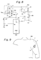
- the state is shown in Figure 9.
- the main body case 1 is adhered to the left anterior arm of a human body (MM).
- a control button 7 formed on the top of the main body case 1 is operated to power on.
- Current from a small battery is supplied to the electrothermal converting means 4 via a control means on an electronic circuit board 3.
- the elecrothermal converting means 4 releases heat for a given period of time. Heat released from the electrothermal converting means 4 is fed to the lesion of the living body via the percutaneous heat conducting means 6.
- the percutaneous heat conducting means 6 preserves heat and gives a comfortable warm feeling to a wide area of the living body.
- Figure 2 shows the second embodiment of the present invention.
- a main body case 1 and its internal construction are identical to those of an embodiment shown in Figure 1.
- Reference 61 denotes a percutaneous heat conducting means composed of a gel base having low viscosity.
- the percutaneous heat conducting means 61 is arranged only around an electrothermal converting means 4.
- the outer margin of the percutaneous heat conducting means 61 is surrounded with adhesive layers 63 each having high viscosity.
- the adhesive layers 63 are composed of adhesive 72 applied on both sides of a ring type supporting member 71.
- the composition of the adhesive 72 is identical to or similar to that of a known adhesive tape.
- the main body case 1 is adhered to a lesion of a living body with the adhesive 72.
- This embodiment is preferred from the viewpoint of improved adhesion.
- the gel base of the percutaneous heat conducting means 61 has low viscosity, the adhesion of the adhesive 72 brings the percutaneous heat conducting means 61 into contact with the living body satisfactorily.
- Figure 3 shows the third embodiment of the present invention.
- a housing 1 and its internal construction are identical to those of an embodiment shown in Figure 1.
- a percutaneous heat conducting means 6 is composed of a two-layered gel base which is intervened with nonwoven cloth, tulle net, or other cloth 8. When the thickness of the percutaneous heat conducting means 6 is as thin as 5 mm or less, the percutaneous heat conducting means 6 may tear. The use of the cloth 8 reinforces the percutaneous heat conducting means 6, and no tearing occurs.
- the percutaneous heat conducting means 6 can be peeled off from the main body 1 effortlessly. This improves ease of use.
- a control unit 51 comprising a small battery and a control circuit, a heating element, a heating element case 55 or a main body case for encapsulating the heating element, and a percutaneous heat conducting means 56 are connected with an electric lead wire 54.
- a battery 53 is placed on the bottom, and an adjustment knob 52 is formed on the front surface.
- the electric lead wire 54 is sheathed with vinyl for electrical insulation.
- the heating element and heat conductor are attached to face outward.
- the bottom of the heating element case 55 is identical to that of the main body case 1 shown in Figure 4.
- the battery 53 may be of D, C, AA, AAA, or a smaller type, or may be replaced by a mains AC power supply.
- 56 denotes a percutaneous heat conducting means which is composed of a gel base. The shape and construction of the percutaneous heat conducting means 56 are identical to those of the aforesaid embodiments.
- Figures 1 to 3 show so-called cordless devices in each of which a small battery control circuit, a heating element, and a percutaneous heat conductor are united as one body and adhered to a living body for treatment.
- the heating temperature of the heating element is controllable remotely.
- a gel base having no viscosity is used for a percutaneous heat conductor.
- the entire main body is adhered to the skin with adhesive tape.
- the electrothermal converting means includes an electrothermal converting element of an appropriate type. Embodiments of the electrothermal converting means will described in conjunction with Figures 6 and 7.
- Reference 41 denotes a heating element made of silver and palladium.
- Reference 42 denotes a heat conductor made mainly of alumina or other ceramic.
- References 43 and 44 denote electric lead wires extending to a control means and a battery.
- the heating element 41 is printed or baked on the heat conductor 42.
- the electric lead wires 43 and 44, and the heat conductor 41 are joined by welding.
- Figure 7 shows a bobbin type heat conductor 42 wound with a heat conductor that is a platinum wire or a tungsten wire.
- References 43 and 44 are electric lead wires which are, similarly to the above embodiment, connected to a control means and a battery.
- Reference 45 in Figure 6 or 7 denotes a portion that appears on the bottom when an electrothermal converting element is incorporated in a heating element case 55 shown in Figure 5.
- the portion that appears on the bottom of the heating element case is not limited to the above surface of the heat conductor 42 but may be the surface of the heating element.
- An electric thermal treatment device is divided into a type in which a heating element and a control unit are connected with a cord, and a cordless portable type.
- the electric thermal treatment device itself is controlled according to the same method.
- the construction and operation of a control means 100 for an electric thermal treatment device of the cordless portable type will now be described.
- an electric thermal treatment device 1 is controlled so that a percutaneous heat conducting means 6 will provide substantially the same heating temperature characteristics as Sen-nen-kyu (conventional moxibustion) and so-called a linear burning moxa treatment device in which natural moxa is employed. Furthermore, using a small battery, current must be controlled effectively to continue treatment for a prolonged period of time.
- control means for the electric thermal treatment device 1 of the present invention includes a microcomputer 86 that adjusts and controls a small current fed from a small battery 81 to make the most of the small current for the purpose of the present invention.
- control means 100 for the electric thermal treatment device 1 of the present invention is provided with a boosting means 102 that boosts the output voltage of the small battery 81 and produces the voltage required for driving the microcomputer 86.
- a heating control circuit 103 for allowing the electrothermal converting means 4 to release heat is incorporated.
- control means 100 A more specific construction of the control means 100 according to the present invention will now be described in detail.
- a plus electrode of a small battery 81 is connected to one end of a coil 82 forming part of the boosting means 102 via a terminal a and to a drain of a field-effect transistor (FET) 83 forming a heating control means 103, via a terminal c.
- FET field-effect transistor
- the source of the FET 83 is connected to one end of a heating element 89 via a terminal d.
- the other end of the coil 82 is connected to a switching terminal Lx of a DC/DC converter chip 90 and to an anode of a diode 84.
- a cathode of the diode 84 is connected to a voltage output terminal OUT of the DC/DC converter chip 90, and to a power input terminal Vdd and one end of a switch 87 of the microcomputer 86, via a terminal b.
- An output terminal of the microcomputer 86 is connected to a gate of the FET 83 of the heating control means 103, via a terminal e.
- the manual switch 87 for manipulating the control means 100 is connected at one end to the power input terminal Vdd.
- the other end of the manual switch 87 is connected to one end of a resistor 88 and to an input terminal IN of the microcomputer.
- the other end of a capacitor 85 and the other end of the resistor 88 are connected to the minus electrode of the battery 81.
- the other end of the heating element 89 is connected to the minus electrode of the battery 81 via a terminal f.
- the ground Vss of the DC/DC converter 90 and the ground GND of the microcomputer are connected to the minus electrode of the battery 81.
- the battery 81 may be a button type Ni-Cd battery (1.2V. Rated capacitor: 50 mAh).
- the DC/DC converter 90 incorporates an oscillator, a chopper, a voltage comparator, and a reference voltage source. The reference voltage source and voltage comparator correct a variation in an output to provide a constant voltage.
- a DC/DC converter includes a coil, a diode, and a capacitor, which are installed externally. Despite the above construction, the DC/DC converter 90 is called a converter.
- the DC/DC converter may, for example, be an RH5RC series product (manufactured by Ricoh Co., Ltd.)
- the microcomputer 86 is incorporated. Assuming that the operating voltage of the microcomputer 86 is 5V, if an output voltage of the small battery 81 is usually 1.2V, the microcomputer 86 does not operate. In the present invention, therefore, the boosting means 102 having the aforesaid construction is employed so that the microcomputer 86 will be actuated with the small current fed from the small battery 81.
- a heating control circuit 103 of the present invention comprises a heating resistor 89 installed in an electrothermal converting means 4 and a current control circuit.
- the current control circuit is, for example, realized with a MOSFET 83.
- the current control circuit including the MOSFET 83 and the electrothermal converting means 4, which make up the heating control circuit 103 are not intervened with any electric or electronic part but are connected directly with each other using a wire.
- the aforesaid construction is preferably for effective release of heat using a very small pulsating current when a small battery is used as a power supply.
- an on-state resistance of a current control circuit or a MOSFET 83 in the present invention is, preferably, smaller than an on-state resistance of a heating resistor 89.
- the gate terminal of the MOSFET 83 forming the current control circuit is connected to the output terminal of the microcomputer 86. According to a given program stored in the microcomputer 86, a given pulse signal is fed to the gate terminal. Thereby, the current control circuit is turned on. While the pulse signal is being fed to the gate terminal, a given current is supplied from the small battery 81 to the heating resistor 89.
- the current control circuit is controlled with a pulse that is supplied by the microcomputer 86 and has a given duration.
- a heating value or temperature of the heating resistor 89 is proportional to a current which the MOSFET 83 forming the current control circuit supplies to the heating resistor 89.
- the heating value or temperature is proportional to a time interval in which the MOSFET 83 is on.
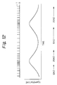
- a pulse generation cycle may be varied. As shown in Figure 12, the heating value or temperature may be set to a higher value for dense pulse durations and to a lower value for sparse pulse durations.
- the heating temperature of the heating resistor 89 can be set to any value by varying an on-stage duty ratio or pulse duration for the MOSFET 83. Furthermore, an intended pattern of temperature variation can be produced.
- a duty ratio or a pulse duration of each control pulse fed to the MOSFET 83 forming the current control circuit varies as time passes.
- the duty ratio or pulse duration of the pulse varies as time passes so that the on-state time interval or cycle will extend.
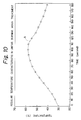
- Figure 10 shows a curve indicating a temperature rise in a heating element that is designed for a known linear burning moxa treatment which uses natural moxa as a heating material placed in contact with the skin.
- a graph A of Figure 10 indicates a temporal function of a temperature change characteristic of the heating element. Past experiments demonstrate that this temperature change characteristic is suitable for a human body.
- the present invention attempts to provide the same temperature change characteristic as that provided by the linear burning moxa treatment. Since the pulse duration of a control pulse to be fed to the MOSFET 83 is modified as shown in Figure 12, a temperature change characteristic similar to an ideal temperature change characteristic for the linear burning moxa treatment can be attained.
- a program for generating a control pulse shown in Figure 12 is implemented in the microcomputer 86.
- the duty ratio is held constant, and the frequency is varied cyclically in the range from 10 to 20 Hz.
- the above temperature change characteristic is introduced merely as an example.
- the electric thermal treatment device of the present invention can adopt a heating method in which various temperature change characteristics can be provided by changing programs existent in the microcomputer 86.
- the microcomputer 86 preferably, includes a repetitive operation facility for repeating a temperature change so that, as shown in Figure 11, a given low temperature is raised to a given high temperature in a given period of time, then, the high temperature is dropped to a given low temperature.
- a temperature change such as that shown in Figure 11 is generally repeated at least three times. Therefore, in the present invention, a program is, preferably, written to repeat a temperature change plotted as a graph B of Figure 11, three times.
- the FET 83 switches between terminals c and d according to whether a drive pulse is supplied.
- the frequency of a drive pulse ranges, for example, from 1 to 50 Hz.
- the frequency or duty ratio of a drive pulse is not restricted to any specific value.
- the heating element releases heat at a temperature that is proportional to the frequency or duty ratio of a drive pulse.
- the heating temperature is controlled according to the frequency or duty ratio of a drive pulse.
- the DC/DC converter 90 compensates for the voltage drop so that a constant voltage will be supplied to the power supply Vdd of the microcomputer all of the time. This allows the heating element to release heat for a time interval required for thermotherapy.
- a gel base is employed for a percutaneous heat conductor. Therefore, a warm feeling can be given continuously over a wide area without causing an uncomfortable thermal stimulus similar to a sting caused by a needle on the skin, or a burn.
Landscapes
- Health & Medical Sciences (AREA)
- General Health & Medical Sciences (AREA)
- Rehabilitation Therapy (AREA)
- Veterinary Medicine (AREA)
- Public Health (AREA)
- Life Sciences & Earth Sciences (AREA)
- Animal Behavior & Ethology (AREA)
- Physical Education & Sports Medicine (AREA)
- Pain & Pain Management (AREA)
- Epidemiology (AREA)
- Engineering & Computer Science (AREA)
- Biomedical Technology (AREA)
- Heart & Thoracic Surgery (AREA)
- Vascular Medicine (AREA)
- Finger-Pressure Massage (AREA)
- Thermotherapy And Cooling Therapy Devices (AREA)
Priority Applications (2)
| Application Number | Priority Date | Filing Date | Title |
|---|---|---|---|
| JP3256889A JP2617839B2 (ja) | 1991-07-02 | 1991-07-02 | 電気温熱治療器 |
| EP92121352A EP0602267A1 (fr) | 1991-07-02 | 1992-12-16 | Dispositif pour traitement thermo-électrique |
Applications Claiming Priority (2)
| Application Number | Priority Date | Filing Date | Title |
|---|---|---|---|
| JP3256889A JP2617839B2 (ja) | 1991-07-02 | 1991-07-02 | 電気温熱治療器 |
| EP92121352A EP0602267A1 (fr) | 1991-07-02 | 1992-12-16 | Dispositif pour traitement thermo-électrique |
Publications (1)
| Publication Number | Publication Date |
|---|---|
| EP0602267A1 true EP0602267A1 (fr) | 1994-06-22 |
Family
ID=26131212
Family Applications (1)
| Application Number | Title | Priority Date | Filing Date |
|---|---|---|---|
| EP92121352A Withdrawn EP0602267A1 (fr) | 1991-07-02 | 1992-12-16 | Dispositif pour traitement thermo-électrique |
Country Status (2)
| Country | Link |
|---|---|
| EP (1) | EP0602267A1 (fr) |
| JP (1) | JP2617839B2 (fr) |
Cited By (3)
| Publication number | Priority date | Publication date | Assignee | Title |
|---|---|---|---|---|
| FR2746296A1 (fr) * | 1996-03-22 | 1997-09-26 | Schbath Pierre | Appareil medical autonome et portatif pour le traitement localise de la peau par chauffage |
| WO2014198220A1 (fr) * | 2013-06-13 | 2014-12-18 | 上海大融医疗器械有限公司 | Dispositif de tête de moxibustion et instrument de moxibustion à lumière de chauffage utilisée comme médicament |
| CN107669481A (zh) * | 2017-11-29 | 2018-02-09 | 河南中医药大学 | 一种艾电透灸理疗装置 |
Families Citing this family (4)
| Publication number | Priority date | Publication date | Assignee | Title |
|---|---|---|---|---|
| JP2955651B2 (ja) * | 1998-01-22 | 1999-10-04 | 工業技術院長 | 接触温熱感覚計測装置 |
| KR100482213B1 (ko) * | 2004-06-28 | 2005-04-14 | 주식회사 세라젬의료기 | 침대형 온열치료매트에 적합한 온열치료장치 |
| EP2665457B1 (fr) * | 2011-01-21 | 2019-06-12 | Carewave Medical, Inc. | Système d'application de stimulation par modules |
| JP7540688B2 (ja) * | 2020-04-20 | 2024-08-27 | 金田 相元 | 電気治療用端子及び電気治療用装置 |
Citations (1)
| Publication number | Priority date | Publication date | Assignee | Title |
|---|---|---|---|---|
| FR2664497A1 (fr) * | 1990-04-09 | 1992-01-17 | Paule Yves | Procedes et dispositifs pour chauffer simultanement plusieurs zones localisees du revetement cutane. |
Family Cites Families (2)
| Publication number | Priority date | Publication date | Assignee | Title |
|---|---|---|---|---|
| JPS61182734U (fr) * | 1985-05-02 | 1986-11-14 | ||
| JP2668547B2 (ja) * | 1988-05-14 | 1997-10-27 | 明宏 藤村 | 施灸装置 |
-
1991
- 1991-07-02 JP JP3256889A patent/JP2617839B2/ja not_active Expired - Lifetime
-
1992
- 1992-12-16 EP EP92121352A patent/EP0602267A1/fr not_active Withdrawn
Patent Citations (1)
| Publication number | Priority date | Publication date | Assignee | Title |
|---|---|---|---|---|
| FR2664497A1 (fr) * | 1990-04-09 | 1992-01-17 | Paule Yves | Procedes et dispositifs pour chauffer simultanement plusieurs zones localisees du revetement cutane. |
Non-Patent Citations (2)
| Title |
|---|
| PATENT ABSTRACTS OF JAPAN vol. 13, no. 431 (C-640)(3779) 26 September 1989 & JP-A-01 166757 ( HIROSHI NAKAJIMA ) 30 June 1989 * |
| PATENT ABSTRACTS OF JAPAN vol. 15, no. 256 (C-0845)28 June 1991 & JP-A-03 085167 ( NKK CORP ) 10 April 1991 * |
Cited By (4)
| Publication number | Priority date | Publication date | Assignee | Title |
|---|---|---|---|---|
| FR2746296A1 (fr) * | 1996-03-22 | 1997-09-26 | Schbath Pierre | Appareil medical autonome et portatif pour le traitement localise de la peau par chauffage |
| WO2014198220A1 (fr) * | 2013-06-13 | 2014-12-18 | 上海大融医疗器械有限公司 | Dispositif de tête de moxibustion et instrument de moxibustion à lumière de chauffage utilisée comme médicament |
| CN107669481A (zh) * | 2017-11-29 | 2018-02-09 | 河南中医药大学 | 一种艾电透灸理疗装置 |
| CN107669481B (zh) * | 2017-11-29 | 2024-05-28 | 河南中医药大学 | 一种艾电透灸理疗装置 |
Also Published As
| Publication number | Publication date |
|---|---|
| JP2617839B2 (ja) | 1997-06-04 |
| JPH057613A (ja) | 1993-01-19 |
Similar Documents
| Publication | Publication Date | Title |
|---|---|---|
| KR100454667B1 (ko) | 승압회로를구비한전기수송주입장치 | |
| US4764164A (en) | Iontophoresis device | |
| US3601126A (en) | High frequency electrosurgical apparatus | |
| CA1299667C (fr) | Stimulateur vaginal pour la regulation de l'incontinence urinaire chez la femme | |
| EP0547482B1 (fr) | Système d'ionophorese comportant des moyens de réduction de l'irritation de la peau | |
| US5423874A (en) | Patch for applying pain reducing electrical energy to the body | |
| EP0308572B1 (fr) | Dispositif d'iontophorèse | |
| US5256137A (en) | Biphasic power source for use in an iontophoretic drug delivery system | |
| JP2002508228A (ja) | 調整された投与を維持する人為的負荷を備えた調整器 | |
| JP2617839B2 (ja) | 電気温熱治療器 | |
| EP0552482B1 (fr) | Dispositif de traitement thermique à très faible encombrement | |
| EP1923096A1 (fr) | Appareil de thérapie électrique à basse fréquence | |
| EP0607472A1 (fr) | Dispositif électrique thermothérapie à fixer sur la peau | |
| US20040059386A1 (en) | Low frequency foot-electric stimulating assistor | |
| CN223182126U (zh) | 一种触摸感应与加热复用电路及护理仪器 | |
| JP2552963Y2 (ja) | 皮膚一体貼着型生体温熱刺激装置 | |
| JP2544271Y2 (ja) | 皮膚一体貼着型生体温熱刺激装置 | |
| CN119154858A (zh) | 一种触摸感应与加热复用电路、方法及护理仪器 | |
| KR100457734B1 (ko) | 치열교정용 전류발생기와 이를 구비한 가철성 교정장치 | |
| JP2669616B2 (ja) | 皮膚貼着型低周波治療器構造体 | |
| JP7685697B2 (ja) | 電流刺激装置 | |
| JPH0234904Y2 (fr) | ||
| JP4217814B2 (ja) | 電位治療器 | |
| KR950012371B1 (ko) | 온열 전기 치료기 | |
| JP2552965Y2 (ja) | 皮膚一体貼着型生体温熱刺激装置 |
Legal Events
| Date | Code | Title | Description |
|---|---|---|---|
| PUAI | Public reference made under article 153(3) epc to a published international application that has entered the european phase |
Free format text: ORIGINAL CODE: 0009012 |
|
| AK | Designated contracting states |
Kind code of ref document: A1 Designated state(s): DE FR GB |
|
| 17P | Request for examination filed |
Effective date: 19940618 |
|
| STAA | Information on the status of an ep patent application or granted ep patent |
Free format text: STATUS: THE APPLICATION HAS BEEN WITHDRAWN |
|
| 18W | Application withdrawn |
Withdrawal date: 19961010 |