EP0602288A1 - Réacteur à lit catalytique mobile - Google Patents
Réacteur à lit catalytique mobile Download PDFInfo
- Publication number
- EP0602288A1 EP0602288A1 EP92204029A EP92204029A EP0602288A1 EP 0602288 A1 EP0602288 A1 EP 0602288A1 EP 92204029 A EP92204029 A EP 92204029A EP 92204029 A EP92204029 A EP 92204029A EP 0602288 A1 EP0602288 A1 EP 0602288A1
- Authority
- EP
- European Patent Office
- Prior art keywords
- catalyst
- bed reactor
- fluid withdrawal
- catalyst bed
- moving
- Prior art date
- Legal status (The legal status is an assumption and is not a legal conclusion. Google has not performed a legal analysis and makes no representation as to the accuracy of the status listed.)
- Granted
Links
Images

Classifications
-
- B—PERFORMING OPERATIONS; TRANSPORTING
- B01—PHYSICAL OR CHEMICAL PROCESSES OR APPARATUS IN GENERAL
- B01J—CHEMICAL OR PHYSICAL PROCESSES, e.g. CATALYSIS OR COLLOID CHEMISTRY; THEIR RELEVANT APPARATUS
- B01J8/00—Chemical or physical processes in general, conducted in the presence of fluids and solid particles; Apparatus for such processes
- B01J8/08—Chemical or physical processes in general, conducted in the presence of fluids and solid particles; Apparatus for such processes with moving particles
- B01J8/12—Chemical or physical processes in general, conducted in the presence of fluids and solid particles; Apparatus for such processes with moving particles moved by gravity in a downward flow
-
- B—PERFORMING OPERATIONS; TRANSPORTING
- B01—PHYSICAL OR CHEMICAL PROCESSES OR APPARATUS IN GENERAL
- B01J—CHEMICAL OR PHYSICAL PROCESSES, e.g. CATALYSIS OR COLLOID CHEMISTRY; THEIR RELEVANT APPARATUS
- B01J8/00—Chemical or physical processes in general, conducted in the presence of fluids and solid particles; Apparatus for such processes
- B01J8/005—Separating solid material from the gas/liquid stream
-
- C—CHEMISTRY; METALLURGY
- C10—PETROLEUM, GAS OR COKE INDUSTRIES; TECHNICAL GASES CONTAINING CARBON MONOXIDE; FUELS; LUBRICANTS; PEAT
- C10G—CRACKING HYDROCARBON OILS; PRODUCTION OF LIQUID HYDROCARBON MIXTURES, e.g. BY DESTRUCTIVE HYDROGENATION, OLIGOMERISATION, POLYMERISATION; RECOVERY OF HYDROCARBON OILS FROM OIL-SHALE, OIL-SAND, OR GASES; REFINING MIXTURES MAINLY CONSISTING OF HYDROCARBONS; REFORMING OF NAPHTHA; MINERAL WAXES
- C10G45/00—Refining of hydrocarbon oils using hydrogen or hydrogen-generating compounds
- C10G45/02—Refining of hydrocarbon oils using hydrogen or hydrogen-generating compounds to eliminate hetero atoms without changing the skeleton of the hydrocarbon involved and without cracking into lower boiling hydrocarbons; Hydrofinishing
- C10G45/14—Refining of hydrocarbon oils using hydrogen or hydrogen-generating compounds to eliminate hetero atoms without changing the skeleton of the hydrocarbon involved and without cracking into lower boiling hydrocarbons; Hydrofinishing with moving solid particles
- C10G45/18—Refining of hydrocarbon oils using hydrogen or hydrogen-generating compounds to eliminate hetero atoms without changing the skeleton of the hydrocarbon involved and without cracking into lower boiling hydrocarbons; Hydrofinishing with moving solid particles according to the "moving-bed" technique
Definitions
- the present invention relates to a moving catalyst bed reactor comprising a normally vertical cylindrical vessel provided at its upper end with a catalyst inlet and a reactant inlet and at its lower end with a catalyst outlet and an effluent outlet, and with a separation device arranged in the vessel near its lower end.
- the separation device in the known moving catalyst bed reactor comprises a downwardly tapering catalyst support having an outer edge which is joined to the wall of the vessel and a central opening which communicates directly with the catalyst outlet.
- a separation device is arranged which comprises several parallel hollow partitions with screened side walls through which effluent can be withdrawn. The partitions extend along the width of the vessel. Between adjacent partitions catalyst passages are defined.
- the moving catalyst bed reactor is suitably used for catalytically treating hydrocarbons, in particular catalytic desulphurization and demetallization of petroleum residues. In general these processes are carried out at elevated pressures and temperatures.
- the relatively long partitions of the separation device are subject to thermal stresses and are therefore easily damaged.
- the moving catalyst bed reactor comprises a normally vertical cylindrical vessel provided at its upper end with a catalyst inlet and a reactant inlet and at its lower end with a catalyst outlet and an effluent outlet, and with a separation device arranged in the vessel near its lower end, the separation device comprises a downwardly tapering catalyst support having an outer edge which is joined to the wall of the vessel and a central opening which communicates directly with the catalyst outlet, the catalyst support is provided with perforations and with fluid withdrawal devices having means for preventing catalyst particles from passing which fluid withdrawal devices are arranged over the perforations and joined to the catalyst support.
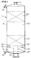
- the moving catalyst bed reactor 1 comprises a normally vertical cylindrical vessel 5, which vessel 5 is provided at its upper end with a catalyst inlet 7 and a reactant inlet 8, and at its lower end the vessel 5 is provided with a catalyst outlet 10 and an effluent outlet 12 communicating with an effluent collecting space 13 in the lower end of the vessel 5.
- the vessel 5 is furthermore provided with a separation device 15 arranged in the vessel 5 near its lower end.
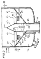
- the separation device 15 comprises a downwardly tapering catalyst support 16, which catalyst support 16 has an outer edge 20 which is joined to the wall of the vessel 5 and a central opening 23 which communicates directly with the catalyst outlet 10 via conduit 25.
- the catalyst support 16 is provided with perforations 26.
- the perforations 26 are situated along the intersections of vertical planes with the catalyst support 16. Please note that in Figure 3 for the sake of clarity not all perforations have been referred to by a reference numeral.
- the catalyst support 16 is furthermore provided with fluid withdrawal devices 30 having means for preventing catalyst particles from passing in the form of screens 32, which fluid withdrawal devices 30 are arranged over the perforations 26 and joined to the catalyst support 16.
- Each fluid withdrawal device 30 is arranged over the perforations 26 along one intersection.
- the fluid withdrawal devices 30 protrude radially from the downwardly tapering catalyst support 16, and the end walls 34 of the fluid withdrawal devices 30 leave a central chamber 35 having a diameter which is not smaller than the diameter of the central opening 23 of the catalyst support 16.
- Each fluid withdrawal device 30 has two vertical side walls 40 each being provided with the screen 32 and a top cover 41.
- the zigzag lines represent the screens 32, and not all side walls and not all screens have been referred to by a reference numeral.
- the vertical side walls 40 of adjacent fluid withdrawal devices 30 define catalyst passages 45 having a constant width.
- the top cover 41 of a fluid withdrawal device 30 consists of two inclined walls 46 and 47 joined by a seam.
- the separation device 15 further includes a conical cover 50 closing the upper end of the central chamber 35 and a tube 53 extending downwardly into the central chamber 35 to the lowermost parts of the screens 32. To facilitate simultaneous removal the tube 53 is secured to the conical cover 50. For the sake of clarity the clearance between the end walls 34 and the tube 35 has been exaggerated.
- the reactor is filled with catalyst, arranged in one bed or in two or more beds, in Figure 1, two catalyst beds 60 and 61 are shown. Between the catalyst beds is arranged a redistribution device 63.
- Reactant(s) is (are) supplied to the upper catalyst bed 60 through reactant inlet 8.
- the reaction starts and product(s) is (are) formed from the reactant(s).
- the reactant(s) and the formed product(s) move downwardly through the upper catalyst bed 60, via the redistribution device 63 and through the lower catalyst bed 61, where the reaction continues.
- the effluent leaves the vessel 5 through the effluent outlet 12.
- the effluent comprising remaining reactant(s) and formed product(s), passes the separation device 15. At first the effluent flows into the catalyst passages 45 between adjacent fluid withdrawal devices 30, then through the screens 32 into the fluid withdrawal devices 30. The effluent leaves the fluid withdrawal devices 30 through the perforations 26 and enters into the effluent collecting space 13 from which it is withdrawn through the effluent outlet 12.
- spent catalyst is removed from the reactor 1 through catalyst outlet 10 and an amount of fresh catalyst sufficient to compensate the withdrawn catalyst is supplied through catalyst inlet 7.
- Spent catalyst flows through the catalyst passages 45, through the openings between adjacent fluid withdrawal devices 30 under the tube 53 and into the conduit 25.
- An advantage of the separator 15 according to the present invention is that the fluid withdrawal devices are arranged in radial directions, and consequently the catalyst passages 45 are substantially perpendicular to the wall of the vessel 5 so that the flow of catalyst particles in the catalyst passages 45 is uniform and the flow in the edges of the catalyst passages 45 cannot be stagnant.
- the top angle of the conical cover 50 and the inclination angles of the inclined walls 46 and 47 are so selected that uniform flow of catalyst particles from the lower catalyst bed 61 into the catalyst passages 45 is secured.
- the number of fluid withdrawal devices is suitably an even number between 10 and 20.
- the perforations 26 are arranged in groups of three and over each group of three perforations a fluid withdrawal device is arranged.
- the catalyst support can be provided with one elongated perforation or with several small perforations or openings.
- the center(s) of the perforation(s) can be situated on the intersection of a vertical plane with the catalyst support or in the neighbourhood of the intersection. In the specification and in the claims the expression "along the intersection" has been used to refer to these possibilities.
- the catalyst support can consists of one section having a constant angle of cone or it can consist of two joined sections having different angles of cone.
- the redistribution device 63 is the redistribution device as described in Applicant's co-pending patent application which has been filed on the same date (Applicant's reference T 9034 EPC).
- the moving catalyst bed reactor of the present invention may contain only one catalyst bed, or more than two.
Landscapes
- Chemical & Material Sciences (AREA)
- Chemical Kinetics & Catalysis (AREA)
- Organic Chemistry (AREA)
- Oil, Petroleum & Natural Gas (AREA)
- Engineering & Computer Science (AREA)
- General Chemical & Material Sciences (AREA)
- Devices And Processes Conducted In The Presence Of Fluids And Solid Particles (AREA)
- Production Of Liquid Hydrocarbon Mixture For Refining Petroleum (AREA)
Priority Applications (5)
| Application Number | Priority Date | Filing Date | Title |
|---|---|---|---|
| DE1992617968 DE69217968T2 (de) | 1992-12-18 | 1992-12-18 | Katalytischer Wanderbettreaktor |
| EP19920204029 EP0602288B1 (fr) | 1992-12-18 | 1992-12-18 | Réacteur à lit catalytique mobile |
| JP34269993A JPH06205965A (ja) | 1992-12-18 | 1993-12-16 | 移動触媒床反応器 |
| CA 2111609 CA2111609A1 (fr) | 1992-12-18 | 1993-12-16 | Reacteur a support de catalyseur mobile |
| CN93112851A CN1040297C (zh) | 1992-12-18 | 1993-12-17 | 移动催化剂床反应器 |
Applications Claiming Priority (1)
| Application Number | Priority Date | Filing Date | Title |
|---|---|---|---|
| EP19920204029 EP0602288B1 (fr) | 1992-12-18 | 1992-12-18 | Réacteur à lit catalytique mobile |
Publications (2)
| Publication Number | Publication Date |
|---|---|
| EP0602288A1 true EP0602288A1 (fr) | 1994-06-22 |
| EP0602288B1 EP0602288B1 (fr) | 1997-03-05 |
Family
ID=8211153
Family Applications (1)
| Application Number | Title | Priority Date | Filing Date |
|---|---|---|---|
| EP19920204029 Expired - Lifetime EP0602288B1 (fr) | 1992-12-18 | 1992-12-18 | Réacteur à lit catalytique mobile |
Country Status (5)
| Country | Link |
|---|---|
| EP (1) | EP0602288B1 (fr) |
| JP (1) | JPH06205965A (fr) |
| CN (1) | CN1040297C (fr) |
| CA (1) | CA2111609A1 (fr) |
| DE (1) | DE69217968T2 (fr) |
Cited By (1)
| Publication number | Priority date | Publication date | Assignee | Title |
|---|---|---|---|---|
| WO2021213747A1 (fr) | 2020-04-20 | 2021-10-28 | Haldor Topsøe A/S | Réacteur pour un procédé catalytique |
Families Citing this family (1)
| Publication number | Priority date | Publication date | Assignee | Title |
|---|---|---|---|---|
| DE10204815B4 (de) * | 2002-02-06 | 2005-09-15 | Eisenmann Maschinenbau Gmbh & Co. Kg | Vorrichtung zur Entsorgung gefährlicher oder hochenergetischer Materialien |
Citations (2)
| Publication number | Priority date | Publication date | Assignee | Title |
|---|---|---|---|---|
| US4357304A (en) * | 1980-07-30 | 1982-11-02 | Shell Oil Company | Moving catalyst bed reactor |
| EP0068558A2 (fr) * | 1981-06-30 | 1983-01-05 | Shell Internationale Researchmaatschappij B.V. | Réacteur à lit catalytique mobile |
-
1992
- 1992-12-18 EP EP19920204029 patent/EP0602288B1/fr not_active Expired - Lifetime
- 1992-12-18 DE DE1992617968 patent/DE69217968T2/de not_active Expired - Fee Related
-
1993
- 1993-12-16 JP JP34269993A patent/JPH06205965A/ja active Pending
- 1993-12-16 CA CA 2111609 patent/CA2111609A1/fr not_active Abandoned
- 1993-12-17 CN CN93112851A patent/CN1040297C/zh not_active Expired - Fee Related
Patent Citations (2)
| Publication number | Priority date | Publication date | Assignee | Title |
|---|---|---|---|---|
| US4357304A (en) * | 1980-07-30 | 1982-11-02 | Shell Oil Company | Moving catalyst bed reactor |
| EP0068558A2 (fr) * | 1981-06-30 | 1983-01-05 | Shell Internationale Researchmaatschappij B.V. | Réacteur à lit catalytique mobile |
Cited By (1)
| Publication number | Priority date | Publication date | Assignee | Title |
|---|---|---|---|---|
| WO2021213747A1 (fr) | 2020-04-20 | 2021-10-28 | Haldor Topsøe A/S | Réacteur pour un procédé catalytique |
Also Published As
| Publication number | Publication date |
|---|---|
| DE69217968D1 (de) | 1997-04-10 |
| JPH06205965A (ja) | 1994-07-26 |
| CN1091335A (zh) | 1994-08-31 |
| EP0602288B1 (fr) | 1997-03-05 |
| DE69217968T2 (de) | 1997-08-14 |
| CN1040297C (zh) | 1998-10-21 |
| CA2111609A1 (fr) | 1994-06-19 |
Similar Documents
| Publication | Publication Date | Title |
|---|---|---|
| US7070745B2 (en) | Multiple bed downflow reactor | |
| US4639354A (en) | Apparatus for the liquid phase hydrotreatment of hydrocarbons in the presence of an expanded or ebullated catalyst bed | |
| US5844006A (en) | Process for producing liquid and, optionally, gaseous products from gaseous reactants | |
| US4380529A (en) | Hydroprocessing reactor with extended operating life | |
| RU2566406C2 (ru) | Суспензионный аппарат | |
| US6093373A (en) | Plate for distributing a multiphase mixture through a catalytic bed | |
| US4708852A (en) | Uniform flow distributing means for a trickle bed flow reactor | |
| US4313908A (en) | Catalytic reactor having bed bypass | |
| EP1056537A1 (fr) | Dispositif de distribution | |
| JPH04363132A (ja) | 蒸留反応器用触媒装置 | |
| JPS61223089A (ja) | バツク混合水素化処理反応器 | |
| US4590045A (en) | Movable catalyst bed reactor | |
| US4229418A (en) | Apparatus for the catalytic treatment of hydrocarbons | |
| EP0766597B1 (fr) | Support de catalyseur et son procede d'utilisation | |
| KR20010012232A (ko) | 슬러리 탄화수소 합성 방법을 위한 다중대역 하향관 | |
| US4357304A (en) | Moving catalyst bed reactor | |
| EP0602287A1 (fr) | Réacteur destiné aux procédés catalytiques | |
| EP0980412B1 (fr) | Deversoir pour suspension a teneur reduite en gaz et en solides. | |
| EP0602288B1 (fr) | Réacteur à lit catalytique mobile | |
| EP0050505B1 (fr) | Dispositif pour mettre en contact un gaz et un liquide | |
| US6689329B2 (en) | Fouling tolerant fixed bed reactor with virtual second bed | |
| US4985209A (en) | Apparatus for injecting a hydrocarbon charge into a reactor | |
| US4330505A (en) | Hydroprocessing reactor with extended operating life | |
| US6692705B2 (en) | Fouling tolerant fixed bed reactor with multi-tier bypass device | |
| US4385033A (en) | Reactor for fouling prone feeds |
Legal Events
| Date | Code | Title | Description |
|---|---|---|---|
| PUAI | Public reference made under article 153(3) epc to a published international application that has entered the european phase |
Free format text: ORIGINAL CODE: 0009012 |
|
| AK | Designated contracting states |
Kind code of ref document: A1 Designated state(s): DE FR GB IT NL |
|
| 17P | Request for examination filed |
Effective date: 19940930 |
|
| 17Q | First examination report despatched |
Effective date: 19951121 |
|
| GRAG | Despatch of communication of intention to grant |
Free format text: ORIGINAL CODE: EPIDOS AGRA |
|
| GRAH | Despatch of communication of intention to grant a patent |
Free format text: ORIGINAL CODE: EPIDOS IGRA |
|
| GRAH | Despatch of communication of intention to grant a patent |
Free format text: ORIGINAL CODE: EPIDOS IGRA |
|
| GRAA | (expected) grant |
Free format text: ORIGINAL CODE: 0009210 |
|
| AK | Designated contracting states |
Kind code of ref document: B1 Designated state(s): DE FR GB IT NL |
|
| REF | Corresponds to: |
Ref document number: 69217968 Country of ref document: DE Date of ref document: 19970410 |
|
| ITF | It: translation for a ep patent filed | ||
| ET | Fr: translation filed | ||
| PLBE | No opposition filed within time limit |
Free format text: ORIGINAL CODE: 0009261 |
|
| 26N | No opposition filed | ||
| PGFP | Annual fee paid to national office [announced via postgrant information from national office to epo] |
Ref country code: FR Payment date: 19981023 Year of fee payment: 7 |
|
| PGFP | Annual fee paid to national office [announced via postgrant information from national office to epo] |
Ref country code: GB Payment date: 19981126 Year of fee payment: 7 |
|
| PGFP | Annual fee paid to national office [announced via postgrant information from national office to epo] |
Ref country code: DE Payment date: 19981230 Year of fee payment: 7 |
|
| PG25 | Lapsed in a contracting state [announced via postgrant information from national office to epo] |
Ref country code: GB Free format text: LAPSE BECAUSE OF NON-PAYMENT OF DUE FEES Effective date: 19991218 |
|
| GBPC | Gb: european patent ceased through non-payment of renewal fee |
Effective date: 19991218 |
|
| PG25 | Lapsed in a contracting state [announced via postgrant information from national office to epo] |
Ref country code: FR Free format text: LAPSE BECAUSE OF NON-PAYMENT OF DUE FEES Effective date: 20000831 |
|
| PG25 | Lapsed in a contracting state [announced via postgrant information from national office to epo] |
Ref country code: DE Free format text: LAPSE BECAUSE OF NON-PAYMENT OF DUE FEES Effective date: 20001003 |
|
| REG | Reference to a national code |
Ref country code: FR Ref legal event code: ST |
|
| PGFP | Annual fee paid to national office [announced via postgrant information from national office to epo] |
Ref country code: NL Payment date: 20001221 Year of fee payment: 9 |
|
| PG25 | Lapsed in a contracting state [announced via postgrant information from national office to epo] |
Ref country code: NL Free format text: LAPSE BECAUSE OF NON-PAYMENT OF DUE FEES Effective date: 20020701 |
|
| NLV4 | Nl: lapsed or anulled due to non-payment of the annual fee |
Effective date: 20020701 |
|
| PG25 | Lapsed in a contracting state [announced via postgrant information from national office to epo] |
Ref country code: IT Free format text: LAPSE BECAUSE OF NON-PAYMENT OF DUE FEES;WARNING: LAPSES OF ITALIAN PATENTS WITH EFFECTIVE DATE BEFORE 2007 MAY HAVE OCCURRED AT ANY TIME BEFORE 2007. THE CORRECT EFFECTIVE DATE MAY BE DIFFERENT FROM THE ONE RECORDED. Effective date: 20051218 |