EP0602409B1 - Cabine pour revêtement par pulvérisation électrostatique de poudre - Google Patents
Cabine pour revêtement par pulvérisation électrostatique de poudre Download PDFInfo
- Publication number
- EP0602409B1 EP0602409B1 EP93118710A EP93118710A EP0602409B1 EP 0602409 B1 EP0602409 B1 EP 0602409B1 EP 93118710 A EP93118710 A EP 93118710A EP 93118710 A EP93118710 A EP 93118710A EP 0602409 B1 EP0602409 B1 EP 0602409B1
- Authority
- EP
- European Patent Office
- Prior art keywords
- booth
- cabin
- plastics material
- hard foam
- foam material
- Prior art date
- Legal status (The legal status is an assumption and is not a legal conclusion. Google has not performed a legal analysis and makes no representation as to the accuracy of the status listed.)
- Expired - Lifetime
Links
- 238000005507 spraying Methods 0.000 title claims abstract description 9
- 239000000843 powder Substances 0.000 title abstract description 19
- 239000004033 plastic Substances 0.000 claims abstract description 51
- 229920003023 plastic Polymers 0.000 claims abstract description 51
- 239000000463 material Substances 0.000 claims description 16
- 239000002184 metal Substances 0.000 claims description 7
- 239000004020 conductor Substances 0.000 claims description 2
- 239000011343 solid material Substances 0.000 claims description 2
- 125000006850 spacer group Chemical group 0.000 claims description 2
- 239000006261 foam material Substances 0.000 claims 10
- 230000001413 cellular effect Effects 0.000 claims 1
- 239000006260 foam Substances 0.000 abstract description 24
- 239000011248 coating agent Substances 0.000 description 3
- 238000000576 coating method Methods 0.000 description 3
- RNFJDJUURJAICM-UHFFFAOYSA-N 2,2,4,4,6,6-hexaphenoxy-1,3,5-triaza-2$l^{5},4$l^{5},6$l^{5}-triphosphacyclohexa-1,3,5-triene Chemical compound N=1P(OC=2C=CC=CC=2)(OC=2C=CC=CC=2)=NP(OC=2C=CC=CC=2)(OC=2C=CC=CC=2)=NP=1(OC=1C=CC=CC=1)OC1=CC=CC=C1 RNFJDJUURJAICM-UHFFFAOYSA-N 0.000 description 2
- 239000004743 Polypropylene Substances 0.000 description 2
- 238000004140 cleaning Methods 0.000 description 2
- 238000010292 electrical insulation Methods 0.000 description 2
- 239000003063 flame retardant Substances 0.000 description 2
- -1 polypropylene Polymers 0.000 description 2
- 229920001155 polypropylene Polymers 0.000 description 2
- 239000007787 solid Substances 0.000 description 2
- 238000010276 construction Methods 0.000 description 1
- 230000005686 electrostatic field Effects 0.000 description 1
- 230000005484 gravity Effects 0.000 description 1
- 239000002557 mineral fiber Substances 0.000 description 1
- 229920002635 polyurethane Polymers 0.000 description 1
- 239000004814 polyurethane Substances 0.000 description 1
- 238000000926 separation method Methods 0.000 description 1
- 239000007921 spray Substances 0.000 description 1
- 230000003746 surface roughness Effects 0.000 description 1
Images
Classifications
-
- B—PERFORMING OPERATIONS; TRANSPORTING
- B05—SPRAYING OR ATOMISING IN GENERAL; APPLYING FLUENT MATERIALS TO SURFACES, IN GENERAL
- B05B—SPRAYING APPARATUS; ATOMISING APPARATUS; NOZZLES
- B05B16/00—Spray booths
- B05B16/40—Construction elements specially adapted therefor, e.g. floors, walls or ceilings
Definitions
- the invention relates to a cabin for electrostatic Spray coating with powder, its cabin walls and Cabin ceiling contain foamed plastic, according to the Preamble of claim 1.
- EP-0 200 681 A1 is a cabin for electrostatic Spray coating with powder known, the cabin walls and cabin ceiling as well as their V-shaped cabin floor a core made of polyurethane, which on the Inside of the cabin with a PVC pad and on its cabin exterior also with a pad Plastic is provided.
- the load-bearing wall elements made of electrical insulating plastic, which on their Inside of the cabin with a layer of polypropylene are provided.
- the polypropylene layer has a thickness of at most 5 mm and their boundaries that limit the cabin interior Has electrically conductive parts on the surface Outside of the cabin a distance of at least 60 mm.
- European patent EP-0 162 784 B1 a plastic cabin is known, which with mineral fibers is reinforced.
- Plastic cabins with smooth interior cabins have the advantage that the coating powder on the smooth interior surfaces adhere very poorly remains. This will clean the cabin when Color change much easier. Serves at the same time the plastic material for electrical insulation of the Cabin interior compared to the cabin environment.
- the cabin interior should have no protrusions if possible and have no cracks, because it is preferred there Coating powder deposits, its cleaning very is time consuming. Furthermore, the parts of the cabin and so that the entire cabin is as light as possible have to make it easier to transport and lighter can be assembled. However, they need Cabin walls, the cabin ceiling and possibly also the cabin floor for mechanical strength and electrical insulation a certain minimum thickness.
- Known cabins which are predominantly made of metal, have the disadvantage over plastic cabins that they have a higher weight, and that at the Cabin interior surfaces due to electrostatic fields and due to surface roughness that cannot always be avoided or gaps between individual cabin parts Powder deposits occur that take a lot of time and need to be cleaned with powder loss.
- the object of the invention is to solve a problem Train plastic cabin so that they quickly, easily and inexpensively can, powder deposits on the inside of the cabin largely avoided and thus the powder cleaning times be significantly reduced, and which ones as a self-supporting cabin construction immediately one ready-to-use cabin forms or existing ones Metal cabins can be retrofitted as interior cabins or as Lining can be used.
- Powder deposits are largely by the invention avoided; this will clean the cabin significantly reduced; the plate elements and the whole Cabin have self-supporting strength; she can as self-supporting, independent and ready-to-operate Cabin used or in an existing metal cabin as a self-supporting interior cabin or as a non-self-supporting cabin Inner lining can be used and then their spray coating room or cabin interior limit; the cabin and its parts have an extreme light weight and can be due to manufactured and assembled quickly and easily will; the cabin can have a complete cabin Cabin floor made of the same material as the cabin walls form or just form a cabin superstructure, which on sits in a cabin substructure.
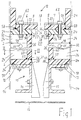
- the cabin shown in Fig. 1 according to the invention for electrostatic spray coating with powder consists in essentially of two longitudinal walls 2 and 4, two Not shown cabin end walls in the same Training like the longitudinal walls, from the longitudinal walls 2 and 4 worn halves 6 and 7 of a cabin ceiling 8, one these cabin parts supporting cabin substructure 10, and an endless circulating filter belt 12 as Cabin floor.
- the cabin without the cabin substructure 10 will also called cabin superstructure.
- At the cabin base 10 are wedge-shaped elements 14 and 15 attached, which opposite each other and a gutter between them form in what excess powder in the cabin falls down on the filter belt 12 by gravity.
- the filter belt 12 does not transport the powder to one shown suction nozzle, which the powder from Aspirated filter belt 12 and in the powder circuit reuse.
- the two halves 6 and 7 of the ceiling 8 form a longitudinal gap 18 between them, through which a transport device reaches, with which objects to be coated in the longitudinal direction of the cabin through the cabin interior 20 can be transported through to this Interior 20 electrostatically coated with powder too will.
- the cabin walls 2 and 4 as well as the ceiling halves 6 and 7 each consist of at least one plate element, which each made of a rigid foam sheet 22 Plastic and from a frame covering their edges is formed from plastic strips 24.
- the inner ones Surfaces 26 of the rigid foam sheets 22 and form inner surfaces 28 of the plastic strips 24 together pore-free smooth cabin interior, which limit the cabin interior 20 in which the to coating objects with powder electrostatically be coated.
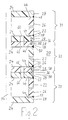
- Cabin of several such plate elements 31, 32 and 33 exist.
- This tongue and groove connection consists of each other opposite grooves 38 in the adjacent Plastic strips 24 and from a strip or so-called spring 40 made of solid plastic material, preferably PVC, which are in each other opposite grooves 38 engages without play.
- All edges 44 of the rigid foam sheets 22 are of the Plastic strips 24 covered.
- the plastic strips 24 are with the rigid foam sheets 22 on their Separation points glued or welded together.
- the welds located in the cabin interior surfaces 26, 28 46, 47, 48, 49, 50, 51, 52 and 53 are completely smooth and lie in the plane of the cabin interior surfaces 26 and 28.
- Other welds 56, 57, 58 and 59 are outside of the cabin interior 20.
- the rigid foam panels 22 and plastic strips 24 close in the cabin interior 20 flush with each other, without edges and protrusions form.
- the rigid foam sheets 22 consist of foamed Plastic with a particularly fine-celled, homogeneous Structure and have a non-porous, smooth surface 26 as cabin interior. This is a flame retardant, flame retardant, self-extinguishing Plastic, such as that known under the name "Forex" is known.
- the rigid foam sheets 22 can be heated and bent into a desired shape when hot will. This means that cabins with round walls, however, smooth cabin interior surfaces 26 and 28 are formed will. Since the rigid foam sheets 22 have a fine cell Have structure, are at their edges 44 cut cells visible as long as they are not from the plastic strips 24 are covered. However, they are exterior surfaces 60 of the rigid foam panels 22 also non-porous smooth.
- the plastic strips 24 not only cover the edges 44 of the rigid foam sheets 22, but also form Frame around the edges 44 of these rigid foam panels 22. So that the plastic strips 44 also thin Rigid foam sheets 22 and the cabin a self-supporting Strength, which is due to the rigid foam panels 22 alone is not possible or only with Rigid foam sheets 22 of very great thickness possible would.
- the plastic strips 24 consist of non-porous, solid solid material, preferably made of PVC. Also the Plastic of the rigid foam sheets 22 can in preferred embodiment be PVC. According to another Embodiment also consist of the plastic strips 24 made of rigid foam with a particularly fine-celled homogeneous structure and smooth surfaces, preferably made of the same rigid foam as that Rigid foam sheets 22.
- the ceiling 8 is shown in FIG. 1 on the longitudinal walls 2 and 4, without having to take up load capacities.
- the ceiling 8 is with the longitudinal walls 2 by means of screws 62 connected, which the rigid foam sheets 22 of Ceiling halves 6 and 7 each with the one below Connect the plastic strip 24 of the longitudinal wall 2 or 4.
- How Show connection holes 66 in the plastic strips 24, can also in the longitudinal direction of the cabin successive plate elements 31, 32 and 33 their adjacent plastic strips 24 each a screw or similar fastener be connected to each other.
- the rigid foam sheets 22 preferably have one Thickness in the range between 5 mm and 30 mm.
- the plastic strips 24 preferably have a thickness between 5 mm and 50 mm.
- the lower plastic strips 24 can according to Fig. 1 with longitudinal grooves 70, in which a Guide rail 72 of the base 10 engages.
- a Guide rail 72 of the base 10 engages.
- the cabin or the cabin so trained Cabin superstructure 11 can also be in a without the substructure 10 already existing metal cabin 74, which in FIG. 1 and 2 is indicated by dash-dotted lines, as self-supporting interior cabin or as a non-self-supporting cabin Inner lining to be installed.
- Such existing Cabins 74 are then advantageous with a Plastic cabin 12 lined inside when out Metal.
- the Distance 78 between the cabin interior surfaces 26 and 28 and external cabin parts made of electrically conductive material for example the metal walls 74 of an existing one Cabin in which the inner cabin 12 is inserted, or lift stands for automatic Spray coaters, at least 60 mm.
- the distance 78 For Compliance with this distance 78 have Plastic strips 24 at the desired distance 78 appropriate width, so that it is used as a spacer Act.
Landscapes
- Body Structure For Vehicles (AREA)
- Application Of Or Painting With Fluid Materials (AREA)
- Paints Or Removers (AREA)
- Electrostatic Spraying Apparatus (AREA)
- Details Or Accessories Of Spraying Plant Or Apparatus (AREA)
Claims (13)
- Cabine servant à déposer une couche de poudre par pulvérisation électrostatique , cabine dont les murs et le plafond contiennent de la matière plastique alvéolaire, caractérisée en ce que les faces intérieures (26, 28), qui délimitent l'intérieur de la cabine (20), d'au moins les murs de la cabine (2, 4) et du plafond de la cabine (8) se composent d'éléments de panneaux (31, 32, 33), reliés les uns aux autres, qui consistent respectivement en un panneau en mousse rigide (22) et en un cadre, recouvrant ses bords, fait de membrures de renforcement en matière plastique (24), en ce que le panneau en mousse rigide (22) a une structure cellulaire particulièrement fine, homogène et a sur ses deux faces respectivement une surface lisse (26, 60), la surface (26) de l'un des côtés du panneau étant une face intérieure de la cabine, délimitant l'intérieur de la cabine, et en ce qu'il est prévu des moyens de liaison (46 à 58, 38, 40, 62, 66), servant à relier les membrures en matière plastique (24) d'éléments de panneaux voisins (31, 32, 33) les unes avec les autres et/ou à d'autres parties de la cabine (22).
- Cabine selon la revendication 1, caractérisée en ce que les membrures (24) en matière plastique sont en PVC.
- Cabine selon la revendication 1 ou 2, caractérisée en ce que les panneaux en mousse rigide (22) forment avec les membrures en matière plastique (24) une cabine autoporteuse ou une superstructure autoporteuse (12) de cabine.
- Cabine selon l'une des revendications 1 à 3, caractérisée en ce que les panneaux en mousse rigide (22) et leurs membrures en matière plastique (24) sont insérés en tant que revêtement intérieur dans une structure de cabine (74) en métal et délimitent dans celle-ci l'intérieur (20) servant au dépôt d'une couche par pulvérisation.
- Cabine selon l'une des revendications 1 à 4, caractérisée en ce que les panneaux en mousse rigide (22) et les membrures en matière plastique (24) sont adjacents les uns aux autres en étant montés à fleur sans fentes et sans saillies dans les faces internes de la cabine et forment ensemble une surface interne de la cabine lisse sans ressaut.
- Cabine selon l'une des revendications 1 à 5, caractérisée en ce que les membrures en matière plastique (24) font saillie sur la face extérieure de la cabine à angle droit sur les faces extérieures (60) des panneaux en mousse rigide (22) et forment de cette façon des écarteurs servant à créer un intervalle défini (78) entre les faces intérieures de la cabine (26, 28) et les éléments extérieurs de la cabine en une matière conductrice de l'électricité.
- Cabine selon la revendication 6, caractérisée en ce que la distance (78) atteint au moins 60 mm.
- Cabine selon l'une des revendications 1 à 7, caractérisée en ce que l'on relie les unes aux autres les membrures en matière plastique (24), voisines les unes des autres, et on les positionne les unes par rapport aux autres par des liaisons à rainure-languette-rainure (38, 40).
- Cabine selon l'une des revendications 1 à 8, caractérisée en ce qu'elle est disposée au moyen d'un dispositif de guidage longitudinal (70, 72), en tant que superstructure (12), de façon réglable dans le sens longitudinal sur une infrastructure (10), en étant toutefois positionnée de façon fixe dans le sens transversal.
- Cabine selon l'une des revendications 1 à 9, caractérisée en ce que les panneaux en mousse rigide (22) ont une épaisseur de l'ordre de 5 mm à 30 mm.
- Cabine selon l'une des revendications 1 à 10, caractérisée en ce que les panneaux en mousse rigide (22) et leurs membrures en matière plastique (24) sont soudés ou collés les uns aux autres.
- Cabine selon l'une des revendications 1 à 11, caractérisée en ce que les membrures en matière plastique (24) sont réalisées en une matière pleine, homogène, non poreuse.
- Cabine selon l'une des revendications 1 à 11, caractérisée en ce que les membrures en matière plastique (24) sont réalisées en mousse rigide, de préférence la même que celle des panneaux en mousse rigide (22) et ont des surfaces lisses, non poreuses.
Applications Claiming Priority (2)
| Application Number | Priority Date | Filing Date | Title |
|---|---|---|---|
| DE4242543A DE4242543A1 (de) | 1992-12-16 | 1992-12-16 | Kabine zum elektrostatischen Sprühbeschichten mit Pulver |
| DE4242543 | 1992-12-16 |
Publications (2)
| Publication Number | Publication Date |
|---|---|
| EP0602409A1 EP0602409A1 (fr) | 1994-06-22 |
| EP0602409B1 true EP0602409B1 (fr) | 1998-01-21 |
Family
ID=6475492
Family Applications (1)
| Application Number | Title | Priority Date | Filing Date |
|---|---|---|---|
| EP93118710A Expired - Lifetime EP0602409B1 (fr) | 1992-12-16 | 1993-11-22 | Cabine pour revêtement par pulvérisation électrostatique de poudre |
Country Status (4)
| Country | Link |
|---|---|
| EP (1) | EP0602409B1 (fr) |
| CN (1) | CN1092342A (fr) |
| AT (1) | ATE162434T1 (fr) |
| DE (2) | DE4242543A1 (fr) |
Families Citing this family (7)
| Publication number | Priority date | Publication date | Assignee | Title |
|---|---|---|---|---|
| DE19500873A1 (de) * | 1995-01-13 | 1996-07-18 | Gema Volstatic Ag | Sprühbeschichtungsvorrichtung |
| DE19500872B4 (de) * | 1995-01-13 | 2005-10-27 | Itw Gema Ag | Pulver-Sprühbeschichtungsvorrichtung |
| DE19957607A1 (de) * | 1999-11-30 | 2001-05-31 | Duerr Systems Gmbh | Kabine zur Oberflächenbehandlung von Fahrzeugkarosserien |
| US6830620B2 (en) | 2000-04-14 | 2004-12-14 | Nordson Corporation | Powder coating booth containment structure |
| US6458209B1 (en) | 2000-04-14 | 2002-10-01 | Nordson Corporation | Powder coating booth containment structure |
| US20040058141A1 (en) * | 2002-09-20 | 2004-03-25 | Shutic Jeffrey R. | Powder coating systems |
| CN100460083C (zh) * | 2006-05-17 | 2009-02-11 | 裕东(中山)机械工程有限公司 | 静电粉末喷涂设备的喷粉室 |
Family Cites Families (12)
| Publication number | Priority date | Publication date | Assignee | Title |
|---|---|---|---|---|
| AT340021B (de) * | 1975-07-18 | 1977-11-25 | Prutscher Fa Johann | Verkleidung fur spritzkabinen und halterahmen |
| DE3015929A1 (de) * | 1980-04-25 | 1981-11-05 | Ernst St.Gallen Lehmann | Kabine zur pulver-spruehbeschichtung |
| DE3315426A1 (de) * | 1983-04-28 | 1984-10-31 | ESB Elektrostatische Sprüh- und Beschichtungsanlagen G.F. Vöhringer GmbH, 7758 Meersburg | Spruehkabine fuer elektrostatische pulverbeschichtungsanlagen |
| DE3441733A1 (de) * | 1983-11-23 | 1985-07-11 | Walter 7707 Engen Stich | Station zur aufnahme von geraetschaften, mess- oder regeleinrichtungen o.dgl. |
| DE3510860A1 (de) * | 1985-03-26 | 1986-10-09 | Dürr GmbH, 7000 Stuttgart | Kabinenkonstruktion |
| CH668008A5 (de) * | 1985-04-30 | 1988-11-30 | H U Ramseier Fa | Elektrostatische pulverbeschichtungsanlage. |
| DE3722849A1 (de) * | 1987-01-28 | 1988-08-18 | Stephan Wedi | Schnellbau-trennwand fuer die einrichtung von kabinen und abtrennungen im sanitaer- und nassbereich |
| DE3919614A1 (de) * | 1989-06-15 | 1990-12-20 | Gema Ransburg Ag | Anlage zum elektrostatischen spruehbeschichten mit pulver |
| DE4116897A1 (de) * | 1991-05-23 | 1992-11-26 | Wurster Gerd | Kabine zum spritzlackieren und farbpulverbeschichten |
| DE9111894U1 (de) * | 1991-09-24 | 1992-02-27 | Jansen, Hatto, 4130 Moers | Sanitärzelle |
| DE4134702A1 (de) * | 1991-10-21 | 1993-04-22 | Gema Volstatic Ag | Kabine zum spruehbeschichten von objekten mit pulver |
| DE9201220U1 (de) * | 1992-02-01 | 1992-06-04 | Aluester GmbH, 2057 Wentorf | Bausatz von Wandelementen aus glasfaserverstärktem Polyester |
-
1992
- 1992-12-16 DE DE4242543A patent/DE4242543A1/de not_active Withdrawn
-
1993
- 1993-11-22 DE DE59308040T patent/DE59308040D1/de not_active Expired - Fee Related
- 1993-11-22 EP EP93118710A patent/EP0602409B1/fr not_active Expired - Lifetime
- 1993-11-22 AT AT93118710T patent/ATE162434T1/de not_active IP Right Cessation
- 1993-12-15 CN CN93120832A patent/CN1092342A/zh active Pending
Also Published As
| Publication number | Publication date |
|---|---|
| EP0602409A1 (fr) | 1994-06-22 |
| ATE162434T1 (de) | 1998-02-15 |
| DE4242543A1 (de) | 1994-06-23 |
| DE59308040D1 (de) | 1998-02-26 |
| CN1092342A (zh) | 1994-09-21 |
Similar Documents
| Publication | Publication Date | Title |
|---|---|---|
| DE69817670T2 (de) | Wandstruktur | |
| DE3115026A1 (de) | Isolierelement | |
| EP0538558A1 (fr) | Cabine de revêtement d'objets par pulvérisation de poudre | |
| DE2758041C2 (de) | Verwendung eines aus mindestens zwei übereinander angeordneten Folien, insbesondere Kunststoffolien, bestehenden Bauelements | |
| EP0102408B1 (fr) | Elément d'isolation | |
| DE3519752C2 (de) | Mineralfaserprodukt als Dämmplatte oder Dämmbahn | |
| DE3725866C2 (de) | Selbsttragende Wärmedämmplatte | |
| DE4242543A1 (de) | Kabine zum elektrostatischen Sprühbeschichten mit Pulver | |
| DE3401868A1 (de) | Fussbodenheizrohr-verlegeplatte | |
| DE3888846T2 (de) | Verbindung zwischen zwei Sandwichtafeln und Modulbausystem mit dieser Verbindung. | |
| EP0940518A1 (fr) | Elément de revêtment pou murs de batiments | |
| EP2402522A2 (fr) | Plaque de construction et/ou d'isolation thermique et système composite d'isolation thermique doté d'une plaque correspondante | |
| EP0074338A1 (fr) | Panneau de revêtement | |
| DE3801445A1 (de) | Flaechenelastisches fussbodenelement | |
| DE3203316C2 (de) | Wandelement | |
| DE19708868C2 (de) | Vorgefertigtes Verkleidungselement zum Verkleiden von Gebäudewänden | |
| DE3733778C2 (fr) | ||
| DE3113888C2 (de) | Verbundfolie für eine Fußbodenheizung | |
| DE2123206A1 (de) | Vorgefertigte Verkleidungsplatte für Innendekorationszwecke | |
| WO2000000704A1 (fr) | Element isolant | |
| DE3346818A1 (de) | Rollenbahn | |
| DE19806939C2 (de) | Anordnung von Platten für die Kabineninnenverkleidung in Fahrzeugen | |
| EP0958995A2 (fr) | Elément de paroi de carrosserie pour véhicule et procédé de fabrication d'un élément pareil | |
| DE2857406C2 (de) | Mehrschichtige Dämmplatte, insbesondere für Fußböden | |
| DE1559383B2 (de) | Versetzbare trennwand |
Legal Events
| Date | Code | Title | Description |
|---|---|---|---|
| PUAI | Public reference made under article 153(3) epc to a published international application that has entered the european phase |
Free format text: ORIGINAL CODE: 0009012 |
|
| 17P | Request for examination filed |
Effective date: 19931122 |
|
| AK | Designated contracting states |
Kind code of ref document: A1 Designated state(s): AT CH DE ES IT LI |
|
| GRAG | Despatch of communication of intention to grant |
Free format text: ORIGINAL CODE: EPIDOS AGRA |
|
| GRAG | Despatch of communication of intention to grant |
Free format text: ORIGINAL CODE: EPIDOS AGRA |
|
| GRAH | Despatch of communication of intention to grant a patent |
Free format text: ORIGINAL CODE: EPIDOS IGRA |
|
| 17Q | First examination report despatched |
Effective date: 19970619 |
|
| GRAH | Despatch of communication of intention to grant a patent |
Free format text: ORIGINAL CODE: EPIDOS IGRA |
|
| GRAA | (expected) grant |
Free format text: ORIGINAL CODE: 0009210 |
|
| AK | Designated contracting states |
Kind code of ref document: B1 Designated state(s): AT CH DE ES IT LI |
|
| PG25 | Lapsed in a contracting state [announced via postgrant information from national office to epo] |
Ref country code: ES Free format text: THE PATENT HAS BEEN ANNULLED BY A DECISION OF A NATIONAL AUTHORITY Effective date: 19980121 |
|
| REF | Corresponds to: |
Ref document number: 162434 Country of ref document: AT Date of ref document: 19980215 Kind code of ref document: T |
|
| REG | Reference to a national code |
Ref country code: CH Ref legal event code: NV Representative=s name: E. BLUM & CO. PATENTANWAELTE Ref country code: CH Ref legal event code: EP |
|
| REF | Corresponds to: |
Ref document number: 59308040 Country of ref document: DE Date of ref document: 19980226 |
|
| ITF | It: translation for a ep patent filed | ||
| PG25 | Lapsed in a contracting state [announced via postgrant information from national office to epo] |
Ref country code: AT Free format text: LAPSE BECAUSE OF NON-PAYMENT OF DUE FEES Effective date: 19981122 |
|
| PLBE | No opposition filed within time limit |
Free format text: ORIGINAL CODE: 0009261 |
|
| STAA | Information on the status of an ep patent application or granted ep patent |
Free format text: STATUS: NO OPPOSITION FILED WITHIN TIME LIMIT |
|
| PG25 | Lapsed in a contracting state [announced via postgrant information from national office to epo] |
Ref country code: LI Free format text: LAPSE BECAUSE OF NON-PAYMENT OF DUE FEES Effective date: 19981130 Ref country code: CH Free format text: LAPSE BECAUSE OF NON-PAYMENT OF DUE FEES Effective date: 19981130 |
|
| 26N | No opposition filed | ||
| REG | Reference to a national code |
Ref country code: CH Ref legal event code: PL |
|
| PG25 | Lapsed in a contracting state [announced via postgrant information from national office to epo] |
Ref country code: DE Free format text: LAPSE BECAUSE OF NON-PAYMENT OF DUE FEES Effective date: 19990901 |
|
| PG25 | Lapsed in a contracting state [announced via postgrant information from national office to epo] |
Ref country code: IT Free format text: LAPSE BECAUSE OF NON-PAYMENT OF DUE FEES Effective date: 20051122 |