EP0602412B1 - Emballage de suture - Google Patents
Emballage de suture Download PDFInfo
- Publication number
- EP0602412B1 EP0602412B1 EP93118796A EP93118796A EP0602412B1 EP 0602412 B1 EP0602412 B1 EP 0602412B1 EP 93118796 A EP93118796 A EP 93118796A EP 93118796 A EP93118796 A EP 93118796A EP 0602412 B1 EP0602412 B1 EP 0602412B1
- Authority
- EP
- European Patent Office
- Prior art keywords
- panel
- folding
- thread
- plate
- folded
- Prior art date
- Legal status (The legal status is an assumption and is not a legal conclusion. Google has not performed a legal analysis and makes no representation as to the accuracy of the status listed.)
- Expired - Lifetime
Links
Images

Classifications
-
- A—HUMAN NECESSITIES
- A61—MEDICAL OR VETERINARY SCIENCE; HYGIENE
- A61B—DIAGNOSIS; SURGERY; IDENTIFICATION
- A61B17/00—Surgical instruments, devices or methods
- A61B17/04—Surgical instruments, devices or methods for suturing wounds; Holders or packages for needles or suture materials
- A61B17/06—Needles ; Sutures; Needle-suture combinations; Holders or packages for needles or suture materials
- A61B17/06114—Packages or dispensers for needles or sutures
- A61B17/06133—Packages or dispensers for needles or sutures of parallelepipedal shape, e.g. made of rectangular or slightly oval panels
- A61B17/06138—Packages or dispensers for needles or sutures of parallelepipedal shape, e.g. made of rectangular or slightly oval panels including a retainer comprising three or more foldable panels
-
- A—HUMAN NECESSITIES
- A61—MEDICAL OR VETERINARY SCIENCE; HYGIENE
- A61B—DIAGNOSIS; SURGERY; IDENTIFICATION
- A61B17/00—Surgical instruments, devices or methods
- A61B17/04—Surgical instruments, devices or methods for suturing wounds; Holders or packages for needles or suture materials
- A61B17/06—Needles ; Sutures; Needle-suture combinations; Holders or packages for needles or suture materials
- A61B17/06114—Packages or dispensers for needles or sutures
- A61B2017/06142—Packages or dispensers for needles or sutures having needle- or suture- retaining members, e.g. holding tabs or needle parks
-
- A—HUMAN NECESSITIES
- A61—MEDICAL OR VETERINARY SCIENCE; HYGIENE
- A61B—DIAGNOSIS; SURGERY; IDENTIFICATION
- A61B17/00—Surgical instruments, devices or methods
- A61B17/04—Surgical instruments, devices or methods for suturing wounds; Holders or packages for needles or suture materials
- A61B17/06—Needles ; Sutures; Needle-suture combinations; Holders or packages for needles or suture materials
- A61B17/06114—Packages or dispensers for needles or sutures
- A61B2017/06157—Packages or dispensers for needles or sutures containing a suture wound in a sinusoidal or zigzag configuration
Definitions
- the invention relates to a suture material pack, for example for surgical suture material, the suture material being contained in a folding card in such a way that it can be pulled out in a simple manner in a controlled manner.
- a suture material package is known from DE 25 32 992 C2, in which the folding card consists of three elongate folding plates arranged next to one another and separated from one another by longitudinal folding lines. These folding plates are folded over one another and inserted in a folded state into a flat envelope which is welded at their edges.
- the sheath is torn open at a longitudinal edge, whereby a part of the top plate of the folding card is also torn off and a portion of the thread is exposed, the thread end being held on a flap of an underlying plate.
- the end of the thread or the one on it attached needle are pulled out of the fixing tab. This is cumbersome, especially when the thread is removed with one hand wearing an operating glove.
- the preamble of claim 1 is based on a suture material package according to EP 0 458 432 A1.
- the folding card consists of four plates arranged in a row next to one another, namely a needle holding plate, a cover plate, a winding plate and a folding plate that can be folded over the winding plate.
- the thread end provided with a needle is inserted into the fixing tabs of the needle holding plate and protrudes in an arc shape beyond the needle holding plate. After opening a sleeve surrounding the folded folding card, the thread end or the needle must also be gripped by hand and freed from the fixing tabs before the thread can be pulled out of the folding card.
- the invention has for its object to provide a suture package that on the one hand holds the thread end securely when inserting the thread during the winding process and fixes the thread winding after the winding process, and on the other hand facilitates the removal of the thread by gripping the thread end.
- the thread holding plate projects beyond the base plate with its fixing tab, and when the cover is torn open, the thread holding plate is pivoted around a longitudinal edge of the base plate, the thread end being between the winding plate and fold-over plate held thread slides out of the fixing tab.
- the thread end is clamped on the pivotable thread holding plate, it detaches when the thread holding plate is pivoted and then stands freely from the part of the folding card that is still folded. The thread end is thus freely offered to the user without having to be pulled out of a fixation.
- a major advantage is that the thread end is held by the thread holding plate while the thread is being wound, the thread being laid mechanically on the winding plate.
- the fold-over plate is then folded over the winding plate in order to hold the thread supply. Then the winding plate is folded over on one side and the thread holding plate on the other side of the base plate, the thread holding plate protruding beyond the end of the base plate. The thread supply and the thread end are thus fixed during folding.
- the folding card is inserted into the sleeve and the sleeve is sealed.
- the thread holding plate is pivoted laterally with respect to the rest of the folding card, the end of the thread detaching from the fixing tab and protruding freely for gripping.
- the thread holding plate is advantageously folded under a folding plate which is adjacent to the longitudinal edge of the base plate facing away from the winding plate.
- This folding plate is folded under the base plate so that the fixing tab is on the side of the thread holding plate facing the base plate, but protrudes beyond the base plate.
- a slotted hole may be provided in the base plate to allow the thread to pass through the base plate.
- the thread wrap is fixed in the folding card and the thread is protected against mechanical damage.
- the folding plate and the thread holding plate preferably have a folding line which runs obliquely (at 45 °) to the base plate and which, when the folding card is folded, forms a crease line controlling the tearing open of the sleeve. When the cover is torn open, the folding card is not damaged or even destroyed at all.
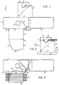
- the folding card 10 shown in Fig. 1 consists of a one-piece blank made of solid paper or cardboard. It has a rectangular, elongated base plate 11, one longitudinal edge 12 of which converts into a fold plate 13 in the form of a fold line.
- the folding plate 13 extends over one half of the base plate 11 and extends beyond the base plate 11 in the longitudinal direction.
- the folding plate 13 is delimited by a folding line 14, which extends obliquely at 45 ° to the longitudinal direction of the base plate 11, the extension of which collides with the longitudinal edge 12 of the base plate and to which the thread holding plate 15 adjoins.
- the thread holding plate 15 is congruent with the folding plate 13 so that it can be folded under the folding plate. Both plates 13 and 15 are essentially triangular.
- a cover plate 18 adjoins via two parallel folding lines 16, 17, which has approximately the same size as the base plate and can be folded over it.
- a folding line 19 with an insertion slot 20 is located on the longitudinal edge of the base plates 11 facing away from the longitudinal edge 12 .
- the winding plate 21 and the fold-over plate 23 are shorter than the base plate 11, which projects over these two plates 21 and 23 at both ends.
- the fold-over plate 23 is essentially congruent with the winding plate 21, but it has a rounded portion 24 on one edge and a tab 25 on its outer longitudinal edge, which can be inserted into the insertion slot 20.
- the base plate 11 is provided with a centering hole 26 into which a centering mandrel of a winding machine can be inserted in order to center the folding card 10 in the winding machine. Furthermore, a U-shaped punched out locking tab 27 is provided on the base plate 10, which extends obliquely at 45 ° to the longitudinal direction of the base plate and under which the folding edge formed by the fold line 14 can be inserted.
- a through opening 28 is provided which runs out into the longitudinal edge via a slot 29.
- the passage opening 28 is located at the corner opposite the folding plate 13.
- a chamfer 30 is provided in this corner of the base plate 11, and a chamfer 31 is provided on the adjacent corner of the cover plate 18.
- a fixing tab 32 for clamping the thread end is punched out on the thread holding plate 15.
- This fixing tab 32 faces the base plate 11. At one edge, it is delimited by an opening 33, which allows the thread end to slide easily out of the fixing tab while the sheath is torn open.
- the thread 34 is inserted through the slot 29 into the through opening 28 and laid on the winding plate 21 in a meandering shape. This laying takes place in the winding machine which has mandrels (not shown) which are arranged at both ends of the winding plate 21. The thread 34 is placed around these mandrels so that it assumes the course shown in FIG. 3. After laying the thread, the fold-over plate 23 is folded over the winding plate 21 and the flap 25 is inserted into the insertion slot 21 in order to secure the thread 34.
- Fig. 4 shows the folding of the superimposed wrapping plate 21 and overfolding plate 23 around the fold line 22 onto the base plate 11, the thread holding plate 15 (together with the folding plate 13) protruding from one end of the base plate 11.
- the thread runs without kinking from the forward-facing fixing tab 32 through the passage opening 28 into the interior of the pocket formed by the winding plate 21 and the folding plate 23, from which the thread loops protrude at both ends.
- the folding of the thread pocket onto the base plate 11 is indicated by the arrow 37.
- the cover plate 18 is placed over the pocket formed by the winding plate and the folding plate (arrow 38).
- Fig. 5 shows the folded folding card from the front, i.e. from the same side in which they are shown in FIGS. 1 to 3 is shown.
- the folding card has a rectangular, elongated shape and it is somewhat longer than the base plate 11 or the cover plate 18 because the thread holding plate 15 with the folding plate 13 protrudes beyond the base plate 11 and the cover plate 18 at one end. At this protruding end is the fixing tab 32, which holds the thread end clamped underneath. From there, the thread runs through the passage opening 28.
- FIG. 6 shows the folded folding card 10 from the rear, which is formed by the base plate 11 with the folding plate 13 folded underneath.
- the folded edge formed by the oblique fold line 14 is pushed under the locking tab 27 of the base plate 11.
- the folding card 10 is inserted into the sleeve 39, which consists of a flat bag made of coated film, which has sealing seams 40 and 41 along its edges. After the folding card has been inserted into the bag opening, it is also closed with a sealing seam, so that the folding card is completely enclosed with the sewing material.
- the sleeve 39 has on one longitudinal edge a tear-open notch 42, on which it can be torn open at the bevels 30, 31 of the folding card. 7, the front film 43 of the cover 39 tears along the fold edge formed by the oblique fold line 14, while the rear film 44 tears open in an uncontrolled manner. This creates a pocket-shaped tear-open pocket 45 of the film 39.
Landscapes
- Health & Medical Sciences (AREA)
- Surgery (AREA)
- Life Sciences & Earth Sciences (AREA)
- Medical Informatics (AREA)
- Animal Behavior & Ethology (AREA)
- Engineering & Computer Science (AREA)
- Biomedical Technology (AREA)
- Heart & Thoracic Surgery (AREA)
- Dentistry (AREA)
- Molecular Biology (AREA)
- Nuclear Medicine, Radiotherapy & Molecular Imaging (AREA)
- General Health & Medical Sciences (AREA)
- Public Health (AREA)
- Veterinary Medicine (AREA)
- Surgical Instruments (AREA)
- Storage Of Web-Like Or Filamentary Materials (AREA)
- Packages (AREA)
Claims (9)
- Emballage de matériau de suture constitué d'un carton de pliage (10) contenu dans une enveloppe (39) pouvant être ouverte par déchirement et ayant une plaque de base (11), une plaque d'enroulement (21) y étant limitrophe latéralement, pour le matériau de suture (34), une plaque de repli (23) pouvant être pliée sur la plaque d'enroulement (21) et une plaque de maintien de fil (15) avec une patte de fixation (32) destinée à fixer une extrémité de fil,
caractérisé en ce que, à l'état plié du carton de pliage (10), la plaque de maintien de fil (15) fait saillie au-dessus de la plaque de base (11) et, lors de l'ouverture par déchirement de l'enveloppe (39) elle est pivotée autour d'une arête longitudinale (12) de la plaque de base (11), l'extrémité du fil maintenu entre la plaque d'enroulement (21) et la plaque de repli (23) ressortant en glissant, hors de la patte de fixation (32). - Emballage de matériau de suture selon la revendication 1, caractérisé en ce que la plaque de maintien de fil (15) est pliée sous une plaque de pliage (13) qui est limitrophe à l'arête longitudinale (12), opposée à la plaque d'enroulement (21), de la plaque de base (11).
- Emballage de matériau de suture selon la revendication 2, caractérisé en ce que la plaque de maintien de fil (15) est reliée a la plaque de pliage (13) au moyen d'une ligne de pliage (14) courant obliquement par rapport à l'arête longitudinale (12) de la plaque de base (11).
- Emballage de matériau de suture selon la revendication 2 ou 3, caractérisé en ce que la plaque d'enroulement (21) est pliée, avec la plaque de repli (23) sur une face de la plaque de base (11), et la plaque de pliage (13) est pliée avec la plaque de maintien de fil (15) repliée sur l'autre face de la plaque de base (11).
- Emballage de matériau de suture selon la revendication 3 ou 4, caractérisé en ce que la ligne de pliage (14) oblique entre plaque de pliage (13) et plaque de maintien de fil (15) est placée extérieurement sur le carton de pliage (10) plié et constitue une piste de guidage pour le déchirement de l'enveloppe (39).
- Emballage de matériau de suture selon l'une des revendications 3 à 5, caractérisé en ce que la plaque de base (11) présente une patte de verrouillage (27) oblique destinée à enserrer la ligne de pliage (14) de la plaque de pliage (13) et de la plaque de maintien de fil (15).
- Emballage de matériau de suture selon l'une des revendications 1 à 6, caractérisé en ce que la plaque de base (11) présente près de la plaque d'enroulement (21) une ouverture de passage (28) fendue destinée au fil (34).
- Emballage de matériau de suture selon l'une des revendications 1 à 7, caractérisé en ce qu'à une extrémité de la plaque de base (11) est limitrophe une plaque de couverture (18) qui est rabattue sur la plaque d'enroulement (21) et la plaque de repli (23), et en ce que la plaque de pliage (13) fait saillie au-dessus de la plaque de base (11) parallèlement à la plaque de couverture (18).
- Emballage de matériau de suture selon l'une des revendications 2 à 8, caractérisé en ce que la plaque de maintien de fil (15) et la plaque de pliage (13) sont sensiblement coïncidentes, par rapport à leur ligne de pliage commune (14).
Applications Claiming Priority (2)
| Application Number | Priority Date | Filing Date | Title |
|---|---|---|---|
| DE4240831A DE4240831C1 (de) | 1992-12-04 | 1992-12-04 | Nahtmaterialpackung |
| DE4240831 | 1992-12-04 |
Publications (2)
| Publication Number | Publication Date |
|---|---|
| EP0602412A1 EP0602412A1 (fr) | 1994-06-22 |
| EP0602412B1 true EP0602412B1 (fr) | 1996-08-28 |
Family
ID=6474395
Family Applications (1)
| Application Number | Title | Priority Date | Filing Date |
|---|---|---|---|
| EP93118796A Expired - Lifetime EP0602412B1 (fr) | 1992-12-04 | 1993-11-23 | Emballage de suture |
Country Status (6)
| Country | Link |
|---|---|
| US (1) | US5433315A (fr) |
| EP (1) | EP0602412B1 (fr) |
| JP (1) | JP2823789B2 (fr) |
| BR (1) | BR9304923A (fr) |
| DE (2) | DE4240831C1 (fr) |
| ES (1) | ES2090824T3 (fr) |
Families Citing this family (9)
| Publication number | Priority date | Publication date | Assignee | Title |
|---|---|---|---|---|
| DE102004035033A1 (de) * | 2004-07-20 | 2006-02-16 | Wabco Gmbh & Co.Ohg | Elektronische Wegfahrsperre |
| US20070170080A1 (en) * | 2006-01-26 | 2007-07-26 | Joshua Stopek | Medical device package |
| US20090209031A1 (en) * | 2006-01-26 | 2009-08-20 | Tyco Healthcare Group Lp | Medical device package |
| US9364215B2 (en) * | 2006-01-26 | 2016-06-14 | Covidien Lp | Medical device package |
| US7600634B2 (en) * | 2006-04-03 | 2009-10-13 | Tyco Healthcare Group Lp | Packaging for surgical sutures |
| CA2604433A1 (fr) * | 2006-10-06 | 2008-04-06 | Tyco Healthcare Group Lp | Emballage de dispositif medical comprenant un orifice auto- perforable |
| US20080171972A1 (en) | 2006-10-06 | 2008-07-17 | Stopek Joshua B | Medical device package |
| US20100096281A1 (en) * | 2007-03-05 | 2010-04-22 | Stopek Joshua B | Apparatus for accessing a medical package |
| US11678961B2 (en) * | 2021-06-04 | 2023-06-20 | The Autoflosser LLC | Packaging for lengths of dental floss |
Family Cites Families (9)
| Publication number | Priority date | Publication date | Assignee | Title |
|---|---|---|---|---|
| US3939969A (en) * | 1974-07-24 | 1976-02-24 | Ethicon, Inc. | Suture package |
| US4089409A (en) * | 1977-02-04 | 1978-05-16 | Ethicon, Inc. | Package for multistrand surgical sutures |
| US4284194A (en) * | 1979-03-12 | 1981-08-18 | American Cyanamid Company | Package for a multiple of sterile sutures with or without needles attached |
| US4496045A (en) * | 1984-06-14 | 1985-01-29 | W. L. Gore & Associates, Inc. | Multi-panel folder for surgical sutures |
| US4533041A (en) * | 1984-07-31 | 1985-08-06 | Ethicon, Inc. | Multistrand suture package with single strand suture dispensing |
| CA2034989C (fr) * | 1990-05-25 | 1995-06-27 | David L. Brown | Dispositif pour l'entreposage de necessaires chirurgicaux a suture |
| US5121836A (en) * | 1990-05-25 | 1992-06-16 | United States Surgical Corporation | Retainer for combined surgical suture-needle device |
| ATE103787T1 (de) * | 1991-06-11 | 1994-04-15 | Braun B Holding Ag | Nahtmaterialpackung. |
| US5174087A (en) * | 1992-02-19 | 1992-12-29 | Mitek Surgical Products, Inc. | Suture anchor assembly packaging system |
-
1992
- 1992-12-04 DE DE4240831A patent/DE4240831C1/de not_active Expired - Fee Related
-
1993
- 1993-11-23 ES ES93118796T patent/ES2090824T3/es not_active Expired - Lifetime
- 1993-11-23 EP EP93118796A patent/EP0602412B1/fr not_active Expired - Lifetime
- 1993-11-23 DE DE59303572T patent/DE59303572D1/de not_active Expired - Fee Related
- 1993-11-30 JP JP5299511A patent/JP2823789B2/ja not_active Expired - Fee Related
- 1993-12-02 BR BR9304923A patent/BR9304923A/pt not_active Application Discontinuation
-
1994
- 1994-11-14 US US08/338,283 patent/US5433315A/en not_active Expired - Fee Related
Also Published As
| Publication number | Publication date |
|---|---|
| BR9304923A (pt) | 1994-06-07 |
| US5433315A (en) | 1995-07-18 |
| JP2823789B2 (ja) | 1998-11-11 |
| DE4240831C1 (de) | 1993-10-07 |
| JPH06211434A (ja) | 1994-08-02 |
| ES2090824T3 (es) | 1996-10-16 |
| EP0602412A1 (fr) | 1994-06-22 |
| DE59303572D1 (de) | 1996-10-02 |
Similar Documents
| Publication | Publication Date | Title |
|---|---|---|
| EP0521170B1 (fr) | Empaquetage pour matériaux de suture | |
| DE69703937T2 (de) | Flexible packung mit gefalteten saugfähigen artikeln | |
| DE4335659C1 (de) | Verpackung mit chirurgischem Nahtmaterial | |
| DE69110860T2 (de) | Packung für vielfache Nähfäden. | |
| DE60105026T2 (de) | Eine aus einer hitzeschrumpfenden plastikhülle bestehende umhüllung zum verpacken zumindest eines objekts | |
| DE3879519T2 (de) | Packung fuer nahtmaterial. | |
| DE69303567T2 (de) | Schachtel mit geschlossener Öffnung zum Festhalten des darin enthaltenen Produktes und mit wiederverschliessbarer Spendeöffnung | |
| DE2820397A1 (de) | Verpackungskarte fuer chirurgisches naehmaterial | |
| EP0602412B1 (fr) | Emballage de suture | |
| DE3636666A1 (de) | Faltschachtel | |
| DE69704747T2 (de) | Verpackungshülle | |
| DE69122071T2 (de) | Nadelschutzvorrichtung für chirurgische Packungen | |
| EP0826338A1 (fr) | Emballage pour multiples sutures | |
| EP0046518B1 (fr) | Emballage pour fil de suture chirurgical | |
| EP0547424B1 (fr) | Emballage pour mouchoirs en papier | |
| DE3340798C2 (de) | Verpackung mit einem Garantieverschluß in Form einer Schachtel aus Karton | |
| DE4430606A1 (de) | Verpackung mit chirurgischem Nahtmaterial | |
| DE69219849T2 (de) | Verpackungsbeutel mit einer Nähfadenhaspel | |
| DE3242349C2 (de) | Faltschachtel | |
| EP0602411B1 (fr) | Emballage de suture | |
| EP0115580B1 (fr) | Empaquetage pour matériaux de suture chirurgicales | |
| DE4121914A1 (de) | Weichpackung aus kunststoffolie zur aufnahme eines stapels von gefalteten erzeugnissen aus papier, tissue ect., insbesondere von papiertaschentuechern und servietten | |
| DE9007553U1 (de) | Weichfolien-Verpackung für quaderförmige Stapel von flexiblen flächigen Gegenständen | |
| DE4020945C2 (de) | Verpackung für einen oder mehrere quaderförmige Magnetband-Behälter | |
| DE847577C (de) | Verschluss fuer Kartonpackungen |
Legal Events
| Date | Code | Title | Description |
|---|---|---|---|
| PUAI | Public reference made under article 153(3) epc to a published international application that has entered the european phase |
Free format text: ORIGINAL CODE: 0009012 |
|
| AK | Designated contracting states |
Kind code of ref document: A1 Designated state(s): CH DE ES FR GB GR IT LI |
|
| 17P | Request for examination filed |
Effective date: 19940722 |
|
| 17Q | First examination report despatched |
Effective date: 19951025 |
|
| GRAH | Despatch of communication of intention to grant a patent |
Free format text: ORIGINAL CODE: EPIDOS IGRA |
|
| GRAH | Despatch of communication of intention to grant a patent |
Free format text: ORIGINAL CODE: EPIDOS IGRA |
|
| GRAA | (expected) grant |
Free format text: ORIGINAL CODE: 0009210 |
|
| AK | Designated contracting states |
Kind code of ref document: B1 Designated state(s): CH DE ES FR GB GR IT LI |
|
| PG25 | Lapsed in a contracting state [announced via postgrant information from national office to epo] |
Ref country code: GR Free format text: LAPSE BECAUSE OF FAILURE TO SUBMIT A TRANSLATION OF THE DESCRIPTION OR TO PAY THE FEE WITHIN THE PRESCRIBED TIME-LIMIT Effective date: 19960828 |
|
| REG | Reference to a national code |
Ref country code: CH Ref legal event code: NV Representative=s name: PATENTANWALTSBUREAU R. A. MASPOLI |
|
| ET | Fr: translation filed | ||
| REF | Corresponds to: |
Ref document number: 59303572 Country of ref document: DE Date of ref document: 19961002 |
|
| GBT | Gb: translation of ep patent filed (gb section 77(6)(a)/1977) |
Effective date: 19960917 |
|
| REG | Reference to a national code |
Ref country code: ES Ref legal event code: FG2A Ref document number: 2090824 Country of ref document: ES Kind code of ref document: T3 |
|
| ITF | It: translation for a ep patent filed | ||
| REG | Reference to a national code |
Ref country code: ES Ref legal event code: FG2A Ref document number: 2090824 Country of ref document: ES Kind code of ref document: T3 |
|
| PLBE | No opposition filed within time limit |
Free format text: ORIGINAL CODE: 0009261 |
|
| STAA | Information on the status of an ep patent application or granted ep patent |
Free format text: STATUS: NO OPPOSITION FILED WITHIN TIME LIMIT |
|
| 26N | No opposition filed | ||
| PGFP | Annual fee paid to national office [announced via postgrant information from national office to epo] |
Ref country code: GB Payment date: 19981105 Year of fee payment: 6 |
|
| PGFP | Annual fee paid to national office [announced via postgrant information from national office to epo] |
Ref country code: FR Payment date: 19981116 Year of fee payment: 6 |
|
| PGFP | Annual fee paid to national office [announced via postgrant information from national office to epo] |
Ref country code: ES Payment date: 19981123 Year of fee payment: 6 |
|
| PGFP | Annual fee paid to national office [announced via postgrant information from national office to epo] |
Ref country code: CH Payment date: 19981126 Year of fee payment: 6 |
|
| PGFP | Annual fee paid to national office [announced via postgrant information from national office to epo] |
Ref country code: DE Payment date: 19981210 Year of fee payment: 6 |
|
| PG25 | Lapsed in a contracting state [announced via postgrant information from national office to epo] |
Ref country code: GB Free format text: LAPSE BECAUSE OF NON-PAYMENT OF DUE FEES Effective date: 19991123 |
|
| PG25 | Lapsed in a contracting state [announced via postgrant information from national office to epo] |
Ref country code: ES Free format text: LAPSE BECAUSE OF NON-PAYMENT OF DUE FEES Effective date: 19991124 |
|
| PG25 | Lapsed in a contracting state [announced via postgrant information from national office to epo] |
Ref country code: LI Free format text: LAPSE BECAUSE OF NON-PAYMENT OF DUE FEES Effective date: 19991130 Ref country code: CH Free format text: LAPSE BECAUSE OF NON-PAYMENT OF DUE FEES Effective date: 19991130 |
|
| GBPC | Gb: european patent ceased through non-payment of renewal fee |
Effective date: 19991123 |
|
| REG | Reference to a national code |
Ref country code: CH Ref legal event code: PL |
|
| PG25 | Lapsed in a contracting state [announced via postgrant information from national office to epo] |
Ref country code: FR Free format text: LAPSE BECAUSE OF NON-PAYMENT OF DUE FEES Effective date: 20000731 |
|
| PG25 | Lapsed in a contracting state [announced via postgrant information from national office to epo] |
Ref country code: DE Free format text: LAPSE BECAUSE OF NON-PAYMENT OF DUE FEES Effective date: 20000901 |
|
| REG | Reference to a national code |
Ref country code: FR Ref legal event code: ST |
|
| REG | Reference to a national code |
Ref country code: ES Ref legal event code: FD2A Effective date: 20001214 |
|
| PG25 | Lapsed in a contracting state [announced via postgrant information from national office to epo] |
Ref country code: IT Free format text: LAPSE BECAUSE OF NON-PAYMENT OF DUE FEES;WARNING: LAPSES OF ITALIAN PATENTS WITH EFFECTIVE DATE BEFORE 2007 MAY HAVE OCCURRED AT ANY TIME BEFORE 2007. THE CORRECT EFFECTIVE DATE MAY BE DIFFERENT FROM THE ONE RECORDED. Effective date: 20051123 |