EP0602462B1 - Appareillage électrique - Google Patents
Appareillage électrique Download PDFInfo
- Publication number
- EP0602462B1 EP0602462B1 EP93119412A EP93119412A EP0602462B1 EP 0602462 B1 EP0602462 B1 EP 0602462B1 EP 93119412 A EP93119412 A EP 93119412A EP 93119412 A EP93119412 A EP 93119412A EP 0602462 B1 EP0602462 B1 EP 0602462B1
- Authority
- EP
- European Patent Office
- Prior art keywords
- contact piece
- switching device
- moving contact
- base
- cup
- Prior art date
- Legal status (The legal status is an assumption and is not a legal conclusion. Google has not performed a legal analysis and makes no representation as to the accuracy of the status listed.)
- Expired - Lifetime
Links
- 239000000463 material Substances 0.000 claims description 4
- 239000012811 non-conductive material Substances 0.000 claims description 3
- 230000000737 periodic effect Effects 0.000 claims 1
- 238000004519 manufacturing process Methods 0.000 description 5
- 239000004020 conductor Substances 0.000 description 4
- 238000006073 displacement reaction Methods 0.000 description 3
- 230000002349 favourable effect Effects 0.000 description 2
- 239000011810 insulating material Substances 0.000 description 2
- 238000004026 adhesive bonding Methods 0.000 description 1
- 238000004140 cleaning Methods 0.000 description 1
- 230000001419 dependent effect Effects 0.000 description 1
- 230000000994 depressogenic effect Effects 0.000 description 1
- 230000000694 effects Effects 0.000 description 1
- 230000013011 mating Effects 0.000 description 1
- 230000000284 resting effect Effects 0.000 description 1
- 238000005476 soldering Methods 0.000 description 1
- 238000003466 welding Methods 0.000 description 1
Images
Classifications
-
- H—ELECTRICITY
- H01—ELECTRIC ELEMENTS
- H01H—ELECTRIC SWITCHES; RELAYS; SELECTORS; EMERGENCY PROTECTIVE DEVICES
- H01H13/00—Switches having rectilinearly-movable operating part or parts adapted for pushing or pulling in one direction only, e.g. push-button switch
- H01H13/02—Details
- H01H13/26—Snap-action arrangements depending upon deformation of elastic members
- H01H13/48—Snap-action arrangements depending upon deformation of elastic members using buckling of disc springs
-
- H—ELECTRICITY
- H01—ELECTRIC ELEMENTS
- H01H—ELECTRIC SWITCHES; RELAYS; SELECTORS; EMERGENCY PROTECTIVE DEVICES
- H01H13/00—Switches having rectilinearly-movable operating part or parts adapted for pushing or pulling in one direction only, e.g. push-button switch
- H01H13/02—Details
- H01H13/12—Movable parts; Contacts mounted thereon
-
- H—ELECTRICITY
- H01—ELECTRIC ELEMENTS
- H01H—ELECTRIC SWITCHES; RELAYS; SELECTORS; EMERGENCY PROTECTIVE DEVICES
- H01H9/00—Details of switching devices, not covered by groups H01H1/00 - H01H7/00
- H01H9/18—Distinguishing marks on switches, e.g. for indicating switch location in the dark; Adaptation of switches to receive distinguishing marks
- H01H9/182—Illumination of the symbols or distinguishing marks
-
- H—ELECTRICITY
- H01—ELECTRIC ELEMENTS
- H01H—ELECTRIC SWITCHES; RELAYS; SELECTORS; EMERGENCY PROTECTIVE DEVICES
- H01H23/00—Tumbler or rocker switches, i.e. switches characterised by being operated by rocking an operating member in the form of a rocker button
- H01H23/003—Tumbler or rocker switches, i.e. switches characterised by being operated by rocking an operating member in the form of a rocker button with more than one electrically distinguishable condition in one or both positions
-
- H—ELECTRICITY
- H01—ELECTRIC ELEMENTS
- H01H—ELECTRIC SWITCHES; RELAYS; SELECTORS; EMERGENCY PROTECTIVE DEVICES
- H01H2300/00—Orthogonal indexing scheme relating to electric switches, relays, selectors or emergency protective devices covered by H01H
- H01H2300/006—Application power roofs
-
- H—ELECTRICITY
- H01—ELECTRIC ELEMENTS
- H01H—ELECTRIC SWITCHES; RELAYS; SELECTORS; EMERGENCY PROTECTIVE DEVICES
- H01H9/00—Details of switching devices, not covered by groups H01H1/00 - H01H7/00
- H01H9/18—Distinguishing marks on switches, e.g. for indicating switch location in the dark; Adaptation of switches to receive distinguishing marks
Definitions
- the invention relates to an electrical switching device according to the preamble of claim 1.
- a sliding and lever switch To operate a sliding roof of a motor vehicle, a sliding and lever switch has become known from DE-PS-39 31 722, which has a push-button or push-button switch and a switch housing with switch contacts, the switch button by a mechanical link guide is guided so that only a sliding movement or a pivoting movement is possible.
- the intention here is to emulate the sliding movement of the sunroof when opening or closing in accordance with the sliding movement of the switch button, while the lifting movement of the lifting roof takes place in accordance with the lifting or lowering actuation of the switch button.
- a disadvantage of the known design of an actuation switch for actuating a sliding / lifting roof is the requirement for an exact slide guide, which results in high demands on the accuracy of the manufacturing tools and a not inconsiderable amount of assembly work.
- An electrical switching device made of electrically non-conductive material with a base for receiving or attaching switching elements, such as contact pieces, wherein at least one contact point formed by a first and a second fixed contact piece and a movable contact piece is arranged on the base and the movable contact piece as a bridge contact is formed and is used for the temporary electrical connection of the fixed contact pieces, is known from US-A-43 52 963 and US-A-43 19 099 and US-Re-30923.
- the base is provided with at least two guides for the movable contact piece, which are designed as bores that are embedded in the base.
- These guides which are provided as guide bores, serve to clearly define the path of movement of the movable contact piece when the movable contact piece is actuated for the purpose of actuating the contact point, and thus to avoid undesired displacements which can lead to incorrect contacting.
- the movable contact piece is provided with webs in a further embodiment of the invention, which are integrally formed or z. B. soldering, welding, gluing, riveting, attached.
- the movable contact piece made of electrically conductive, spring-hard material, for. B. AgPd. Conveniently, d. H. favorable in terms of manufacturing costs, it is manufactured as a stamped and bent part, which is favorable for automatic production.
- a preferred embodiment of the invention provides that the movable contact piece is designed as a triangle, its surface being curved in the form of a dome and resting with its corner points on the base, while its curved central region is at a distance from the base.
- the corner points can each have pits directed towards the base for better contact with the first fixed contact piece arranged on the base.
- the curved central region of the triangular, movable contact piece also has a beading facing the base, which is used for contacting the second fixed contact piece, which is located below on the base.
- An expedient embodiment provides that the first fixed contact piece is divided into three parts and is arranged at each of the corner points of the triangular movable contact piece.
- a further embodiment of the invention provides that the webs for guiding the movable contact piece on its side edges, preferably in the center, ie. H. at half length, are arranged and engage in the corresponding guide holes located below in the base.
- the movable contact piece is a monostable, i.e. H. self-resetting contact spring designed, which opens the respective contact in the rest position.
- the base which serves as a contact carrier, can be made of hard paper, for. B. printed circuit boards, or another suitable insulating material, d. H. with sufficient electrical and mechanical strength, in which the fixed contact pieces are injected or mechanically attached.
- line paths are provided, which are used as conductor tracks, such as. B. common and known in printed circuit boards, or as in corresponding recesses, for. B. grooves, recessed conductors can be formed and are galvanically connected to the fixed contact pieces.
- each contact point consists of very few parts, of which only the movable contact piece, as the name suggests, is movable by applying its spring-elastic central region to close the contact and after relief automatically resets, while the fixed contact pieces are captively connected to the base.
- the switching device according to the invention is particularly suitable for low switching currents, but high switching currents can also be controlled.
- the movable contact piece with a spherically curved triangular surface provided according to the invention, when it is actuated, H. when the outer curvature is depressed, additionally the intended effect that, due to the slight displacement of the corner points caused thereby, the contact surface is automatically cleaned when switching, and incorrect contacts are thereby avoided.
- the guidance of the movable contact piece effected by means of integrally formed webs is on the one hand very easy to manufacture and on the other hand very expedient, since a displacement of the middle contact is thus excluded, while the previously described contact cleaning of the external contacts is nevertheless ensured.
- Another advantage is the very compact design and versatility of the switching device according to the invention, which allows a large number of switching operations to be implemented in the smallest space, be it as a rocker, push button or slide switch designed as one-way or multi-way buttons.
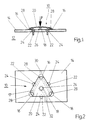
- FIG. 1 shows a longitudinal section of a contact point 10 of an electrical switching device 12, which is provided in particular for use in motor vehicles and devices with comparable electrical parameters. Because of the structurally provided small contact distances, which accordingly lead to short switching distances, the low-voltage range in particular is the preferred area of application for this switching device.
- the contact point 10 in the switching device 12 according to the invention is arranged on a base 14 which serves as a contact carrier for first and second fixed contact pieces 16, 18 which are electrically insulated from one another.
- the base 14 consists of electrically non-conductive material, e.g. b. Insulating material which, in addition to having sufficient electrical strength, also has sufficient mechanical strength.
- a movable contact piece 20 is used to connect the first and second fixed contact pieces 16, 18, which are electrically insulated from one another in the idle state, and connects the two fixed contact pieces 16, 18 to one another in an electrically conductive manner as a contact bridge when pressed by depression.
- the movable contact piece 20 has a triangular shape, the first fixed three-piece contact piece 16 being arranged at the locations opposite the corner points on the base 14, while In the center of the triangle enclosed by the corner points, the second fixed contact piece 18, which is insulated against it, is arranged in the base 14. On each side of the triangle there is half a length of a web 22 directed towards the base 14, which in the example shown is integrally connected to the movable contact piece 20 and engages in a corresponding recess 24 in the base 14.
- This recess 24 is made as a bore and serves as a guide for the movable contact piece 20 to ensure that the second fixed contact point 18 and the contact surface 20 located above it, formed as a dimpling 26, are always flush with one another, and thus ensures reliable contacting is.
- the corner areas of the triangular movable contact piece 20 also each have a dome 28, i. H. a bulge directed towards the base 14, which serves for better contacting with the respectively assigned first fixed contact piece 16 arranged on the base 14.
- a dome 28 i. H. a bulge directed towards the base 14, which serves for better contacting with the respectively assigned first fixed contact piece 16 arranged on the base 14.
- both cases i.e. H. both in the conical shape 26 in the center of the triangle and in the conical shape 28 at the corner points of the movable contact piece 20, which is designed as an equilateral triangle, are dome-shaped, ie. H. hemispherical, designed and thus offer the guarantee that, regardless of the position of the movable contact piece 20, a reliable point contact with the associated first or second fixed contact pieces 16, 18 takes place.
- the movable contact piece 20 has a bulge directed away from the base 14, which is permanently impressed on the movable contact piece 20, which is preferably made of resilient flat material as a stamped and bent part, and thus causes an automatic reset. So if the movable contact piece is acted upon in the direction of arrow F, this takes place when the movable contact piece 20 is relieved, its return to the starting position shown in FIG. 1.
- the contact point 10 has a first fixed contact piece 16 with three contact points which, as said, are arranged at the corner points of an equilateral triangle and are connected to one another by means of line paths 17 arranged in the base 14.
- first connecting line 30 To connect the contact point 10 with the periphery, for. B. with connection contacts of the switching device 12, not shown here, one of the first fixed contact pieces 16 arranged in the base 14 is connected to a first connecting line 30 and the second fixed contact piece 18 to a second connecting line 32.
- the further course of the first and second connecting lines 30, 32 is not shown in more detail in the example shown.
- these connecting conductors 30, 32 can be designed both as conductor tracks running on the surface and as contact strips which work together with corresponding mating contact surfaces when installed in a switch housing (also not shown here) and thus fulfill the intended electrical function.
Landscapes
- Push-Button Switches (AREA)
- Investigating Strength Of Materials By Application Of Mechanical Stress (AREA)
Claims (9)
- Appareil interrupteur électrique (12), en particulier interrupteur à touche pour agir sur ou commander des organes de réglage pour des dispositifs à actionnement électrique dans des véhicules automobiles, comprenant un socle (14) en un matériau non-conducteur de l'électricité, sur lequel est disposé au moins un contact (10) formé par au moins une première et une deuxième pièces de contact fixes (16, 18) ainsi que par une pièce de contact mobile (20) qui est réalisée sous la forme d'un pont de contact et sert à établir une liaison électrique temporaire entre les pièces de contact fixes (16, 18), caractérisé par le fait que le socle (14) est muni d'au moins deux guides (24) pour la pièce de contact mobile (20), guides (24) qui sont réalisés sous la forme de trous, ménagés dans le socle (14) et dans lesquels pénètre la pièce de contact mobile (20).
- Appareil interrupteur suivant la revendication 1, caractérisé par le fait que la pièce de contact mobile (20) présente au moins deux pieds (22) qui pénètrent dans les trous de guidage (24).
- Appareil interrupteur suivant la revendication 2, caractérisé par le fait que les pieds de guidage (22) sont réalisés d'une seule pièce avec la pièce de contact mobile (20).
- Appareil interrupteur suivant l'une des revendications précédentes, caractérisé par le fait que la pièce de contact mobile (20) est de forme triangulaire.
- Appareil interrupteur suivant l'une des revendications 2 à 4, caractérisé par le fait que la pièce de contact mobile (20) est bombée en forme de calotte à l'encontre du sens dans lequel les pieds de guidage (22) font saillie.
- Appareil interrupteur suivant l'une des revendications précédentes, caractérisé par le fait que la pièce de contact mobile (20) est constituée d'un matériau élastique.
- Appareil interrupteur suivant la revendication 4, 5 et 6, caractérisé par le fait que la pièce de contact mobile (20) est à auto-rappel.
- Appareil interrupteur suivant l'une des revendications 2 à 7, caractérisé par le fait que la pièce de contact mobile (20) présente des emboutis (26, 28) orientés dans la direction des pieds de guidage (22), qui y sont prévus.
- Appareil interrupteur suivant l'une des revendications précédentes, caractérisé par le fait qu'un premier embouti (26) est disposé à chaque angle de la pièce de contact mobile (20) de forme triangulaire et un deuxième embouti (28) est disposé au centre de la surface triangulaire, lesdits emboutis étant orientés en opposition au bombement en forme de calotte de la pièce de contact mobile et correspondant aux première et deuxième pièces de contact fixes (16, 18) disposées sur le socle.
Applications Claiming Priority (4)
| Application Number | Priority Date | Filing Date | Title |
|---|---|---|---|
| DE19924242100 DE4242100B4 (de) | 1992-12-14 | 1992-12-14 | Elektrisches Schaltgerät |
| DE4242100 | 1992-12-14 | ||
| DE9300501U DE9300501U1 (de) | 1992-12-14 | 1993-01-21 | Elektrisches Schaltgerät |
| DE9300501U | 1993-01-21 |
Publications (2)
| Publication Number | Publication Date |
|---|---|
| EP0602462A1 EP0602462A1 (fr) | 1994-06-22 |
| EP0602462B1 true EP0602462B1 (fr) | 1996-10-23 |
Family
ID=25921310
Family Applications (1)
| Application Number | Title | Priority Date | Filing Date |
|---|---|---|---|
| EP93119412A Expired - Lifetime EP0602462B1 (fr) | 1992-12-14 | 1993-12-02 | Appareillage électrique |
Country Status (3)
| Country | Link |
|---|---|
| EP (1) | EP0602462B1 (fr) |
| DE (2) | DE9300501U1 (fr) |
| ES (1) | ES2098637T3 (fr) |
Cited By (2)
| Publication number | Priority date | Publication date | Assignee | Title |
|---|---|---|---|---|
| DE19940543A1 (de) * | 1999-08-26 | 2001-03-01 | Abb Patent Gmbh | Elektrisches Schaltgerät |
| US10559440B2 (en) | 2016-03-30 | 2020-02-11 | Shanghai Yanfeng Jinqiao Automotive Trim Systems Co. Ltd. | Switch mechanism for a vehicle interior component |
Families Citing this family (1)
| Publication number | Priority date | Publication date | Assignee | Title |
|---|---|---|---|---|
| DE102006010811B4 (de) * | 2006-03-07 | 2018-03-01 | Huf Hülsbeck & Fürst Gmbh & Co. Kg | Schaltelement und Betätigungsvorrichtung damit sowie Türgriff mit dieser Betätigungsvorrichtung |
Family Cites Families (4)
| Publication number | Priority date | Publication date | Assignee | Title |
|---|---|---|---|---|
| US3796843A (en) * | 1973-01-02 | 1974-03-12 | Bomar Instr Corp | Calculator keyboard switch with disc spring contact and printed circuit board |
| US4352963A (en) * | 1980-08-05 | 1982-10-05 | Texas Instruments Incorporated | Low profile microswitches, particularly useful for the composition of keyboards and method of making |
| US4319099A (en) * | 1979-05-03 | 1982-03-09 | Atari, Inc. | Dome switch having contacts offering extended wear |
| DE3931722C2 (de) * | 1989-09-22 | 1994-04-28 | Trw Messmer | Schiebe- und Hebeschalter, insbesondere für ein Schiebe-Hebedach eines Kraftfahrzeuges |
-
1993
- 1993-01-21 DE DE9300501U patent/DE9300501U1/de not_active Expired - Lifetime
- 1993-12-02 DE DE59304291T patent/DE59304291D1/de not_active Expired - Fee Related
- 1993-12-02 ES ES93119412T patent/ES2098637T3/es not_active Expired - Fee Related
- 1993-12-02 EP EP93119412A patent/EP0602462B1/fr not_active Expired - Lifetime
Cited By (2)
| Publication number | Priority date | Publication date | Assignee | Title |
|---|---|---|---|---|
| DE19940543A1 (de) * | 1999-08-26 | 2001-03-01 | Abb Patent Gmbh | Elektrisches Schaltgerät |
| US10559440B2 (en) | 2016-03-30 | 2020-02-11 | Shanghai Yanfeng Jinqiao Automotive Trim Systems Co. Ltd. | Switch mechanism for a vehicle interior component |
Also Published As
| Publication number | Publication date |
|---|---|
| DE9300501U1 (de) | 1993-04-01 |
| DE59304291D1 (de) | 1996-11-28 |
| ES2098637T3 (es) | 1997-05-01 |
| EP0602462A1 (fr) | 1994-06-22 |
Similar Documents
| Publication | Publication Date | Title |
|---|---|---|
| DE60007537T2 (de) | Verbesserter elektroschalter mit fühlbarem effekt und einen einzigen schaltglied | |
| DE3019886A1 (de) | Fluessigkeits- und gasdichter schiebeschalter | |
| EP0857351B1 (fr) | Commutateur avec film conducteur comme contact fixe et raccordement aux contacts de connexion | |
| DE2515185A1 (de) | Elektrischer schnappschalter | |
| DE1920784A1 (de) | Schiebeschalter fuer Geraete mit einem von einer Isolierstoffplatte getragenen Leiternetz | |
| DE19726149A1 (de) | Schalteranordnung | |
| DE4420665B4 (de) | Schalter | |
| DE2162460A1 (de) | Elektrischer Schalter | |
| DE19812249C1 (de) | Elektrischer Schalter | |
| EP0602462B1 (fr) | Appareillage électrique | |
| DE2439697A1 (de) | Druckschalter | |
| DE19627294A1 (de) | Wipptaster | |
| DE3442173A1 (de) | Elektrischer schalter gedrungener bauart | |
| DE2950665A1 (de) | Tastwahlblock fuer fernsprechgeraete | |
| DE2452944C3 (de) | Tastenschaltersystem | |
| EP1008159A1 (fr) | Commutateur pourvu d'une rampe de soulevement | |
| EP1686600B1 (fr) | Commutateur bipolaire | |
| DE19621192A1 (de) | Niederspannungsschaltgerät | |
| DE3324253C2 (fr) | ||
| EP0614204A2 (fr) | Calotte d'interrupteur pour bouton-poussoir | |
| DE102007009006B4 (de) | Tastschalter für ein Kraftfahrzeug | |
| DE4223077C2 (de) | Kontaktanordnung | |
| DE3329827A1 (de) | Tastenschalter | |
| DE2122992B2 (de) | Elektrischer schalter | |
| DE2907894C2 (fr) |
Legal Events
| Date | Code | Title | Description |
|---|---|---|---|
| PUAI | Public reference made under article 153(3) epc to a published international application that has entered the european phase |
Free format text: ORIGINAL CODE: 0009012 |
|
| AK | Designated contracting states |
Kind code of ref document: A1 Designated state(s): DE ES IT PT |
|
| 17P | Request for examination filed |
Effective date: 19940722 |
|
| 17Q | First examination report despatched |
Effective date: 19951110 |
|
| GRAG | Despatch of communication of intention to grant |
Free format text: ORIGINAL CODE: EPIDOS AGRA |
|
| GRAH | Despatch of communication of intention to grant a patent |
Free format text: ORIGINAL CODE: EPIDOS IGRA |
|
| GRAH | Despatch of communication of intention to grant a patent |
Free format text: ORIGINAL CODE: EPIDOS IGRA |
|
| GRAA | (expected) grant |
Free format text: ORIGINAL CODE: 0009210 |
|
| AK | Designated contracting states |
Kind code of ref document: B1 Designated state(s): DE ES IT PT |
|
| ITF | It: translation for a ep patent filed | ||
| REF | Corresponds to: |
Ref document number: 59304291 Country of ref document: DE Date of ref document: 19961128 |
|
| REG | Reference to a national code |
Ref country code: PT Ref legal event code: SC4A Free format text: AVAILABILITY OF NATIONAL TRANSLATION Effective date: 19961230 |
|
| REG | Reference to a national code |
Ref country code: ES Ref legal event code: FG2A Ref document number: 2098637 Country of ref document: ES Kind code of ref document: T3 |
|
| PLBE | No opposition filed within time limit |
Free format text: ORIGINAL CODE: 0009261 |
|
| STAA | Information on the status of an ep patent application or granted ep patent |
Free format text: STATUS: NO OPPOSITION FILED WITHIN TIME LIMIT |
|
| 26N | No opposition filed | ||
| PGFP | Annual fee paid to national office [announced via postgrant information from national office to epo] |
Ref country code: PT Payment date: 19981116 Year of fee payment: 6 |
|
| PG25 | Lapsed in a contracting state [announced via postgrant information from national office to epo] |
Ref country code: PT Free format text: LAPSE BECAUSE OF NON-PAYMENT OF DUE FEES Effective date: 20000630 |
|
| REG | Reference to a national code |
Ref country code: PT Ref legal event code: MM4A Free format text: LAPSE DUE TO NON-PAYMENT OF FEES Effective date: 20000630 |
|
| PGFP | Annual fee paid to national office [announced via postgrant information from national office to epo] |
Ref country code: ES Payment date: 20031222 Year of fee payment: 11 |
|
| PG25 | Lapsed in a contracting state [announced via postgrant information from national office to epo] |
Ref country code: ES Free format text: LAPSE BECAUSE OF NON-PAYMENT OF DUE FEES Effective date: 20041203 |
|
| PG25 | Lapsed in a contracting state [announced via postgrant information from national office to epo] |
Ref country code: IT Free format text: LAPSE BECAUSE OF NON-PAYMENT OF DUE FEES;WARNING: LAPSES OF ITALIAN PATENTS WITH EFFECTIVE DATE BEFORE 2007 MAY HAVE OCCURRED AT ANY TIME BEFORE 2007. THE CORRECT EFFECTIVE DATE MAY BE DIFFERENT FROM THE ONE RECORDED. Effective date: 20051202 |
|
| PGFP | Annual fee paid to national office [announced via postgrant information from national office to epo] |
Ref country code: DE Payment date: 20060217 Year of fee payment: 13 |
|
| REG | Reference to a national code |
Ref country code: ES Ref legal event code: FD2A Effective date: 20041203 |
|
| PG25 | Lapsed in a contracting state [announced via postgrant information from national office to epo] |
Ref country code: DE Free format text: LAPSE BECAUSE OF NON-PAYMENT OF DUE FEES Effective date: 20070703 |