EP0602469A2 - Méthode d'enregistrement sur bande magnétique à pistes obliques - Google Patents
Méthode d'enregistrement sur bande magnétique à pistes obliques Download PDFInfo
- Publication number
- EP0602469A2 EP0602469A2 EP93119477A EP93119477A EP0602469A2 EP 0602469 A2 EP0602469 A2 EP 0602469A2 EP 93119477 A EP93119477 A EP 93119477A EP 93119477 A EP93119477 A EP 93119477A EP 0602469 A2 EP0602469 A2 EP 0602469A2
- Authority
- EP
- European Patent Office
- Prior art keywords
- track
- signals
- bits
- information
- signal
- Prior art date
- Legal status (The legal status is an assumption and is not a legal conclusion. Google has not performed a legal analysis and makes no representation as to the accuracy of the status listed.)
- Granted
Links
- 238000000034 method Methods 0.000 title claims description 17
- 230000010355 oscillation Effects 0.000 claims description 3
- 230000001419 dependent effect Effects 0.000 claims description 2
- 238000000926 separation method Methods 0.000 claims description 2
- 230000005236 sound signal Effects 0.000 abstract description 2
- 239000000243 solution Substances 0.000 description 19
- 238000011156 evaluation Methods 0.000 description 6
- 230000001360 synchronised effect Effects 0.000 description 4
- 238000005259 measurement Methods 0.000 description 2
- 101100125452 Arabidopsis thaliana ICR1 gene Proteins 0.000 description 1
- 101000653235 Homo sapiens Protein-glutamine gamma-glutamyltransferase K Proteins 0.000 description 1
- 102100030944 Protein-glutamine gamma-glutamyltransferase K Human genes 0.000 description 1
- 230000002238 attenuated effect Effects 0.000 description 1
- 238000001514 detection method Methods 0.000 description 1
- 238000011161 development Methods 0.000 description 1
- 230000018109 developmental process Effects 0.000 description 1
- 238000010586 diagram Methods 0.000 description 1
- 238000012545 processing Methods 0.000 description 1
- 230000001172 regenerating effect Effects 0.000 description 1
- 230000008929 regeneration Effects 0.000 description 1
- 238000011069 regeneration method Methods 0.000 description 1
- 230000002441 reversible effect Effects 0.000 description 1
- 230000002123 temporal effect Effects 0.000 description 1
- 230000001960 triggered effect Effects 0.000 description 1
Images


Classifications
-
- G—PHYSICS
- G11—INFORMATION STORAGE
- G11B—INFORMATION STORAGE BASED ON RELATIVE MOVEMENT BETWEEN RECORD CARRIER AND TRANSDUCER
- G11B5/00—Recording by magnetisation or demagnetisation of a record carrier; Reproducing by magnetic means; Record carriers therefor
- G11B5/008—Recording on, or reproducing or erasing from, magnetic tapes, sheets, e.g. cards, or wires
- G11B5/00813—Recording on, or reproducing or erasing from, magnetic tapes, sheets, e.g. cards, or wires magnetic tapes
- G11B5/00847—Recording on, or reproducing or erasing from, magnetic tapes, sheets, e.g. cards, or wires magnetic tapes on transverse tracks
- G11B5/0086—Recording on, or reproducing or erasing from, magnetic tapes, sheets, e.g. cards, or wires magnetic tapes on transverse tracks using cyclically driven heads providing segmented tracks
-
- G—PHYSICS
- G11—INFORMATION STORAGE
- G11B—INFORMATION STORAGE BASED ON RELATIVE MOVEMENT BETWEEN RECORD CARRIER AND TRANSDUCER
- G11B15/00—Driving, starting or stopping record carriers of filamentary or web form; Driving both such record carriers and heads; Guiding such record carriers or containers therefor; Control thereof; Control of operating function
- G11B15/18—Driving; Starting; Stopping; Arrangements for control or regulation thereof
- G11B15/1808—Driving of both record carrier and head
- G11B15/1875—Driving of both record carrier and head adaptations for special effects or editing
-
- G—PHYSICS
- G11—INFORMATION STORAGE
- G11B—INFORMATION STORAGE BASED ON RELATIVE MOVEMENT BETWEEN RECORD CARRIER AND TRANSDUCER
- G11B27/00—Editing; Indexing; Addressing; Timing or synchronising; Monitoring; Measuring tape travel
- G11B27/10—Indexing; Addressing; Timing or synchronising; Measuring tape travel
- G11B27/19—Indexing; Addressing; Timing or synchronising; Measuring tape travel by using information detectable on the record carrier
- G11B27/28—Indexing; Addressing; Timing or synchronising; Measuring tape travel by using information detectable on the record carrier by using information signals recorded by the same method as the main recording
- G11B27/32—Indexing; Addressing; Timing or synchronising; Measuring tape travel by using information detectable on the record carrier by using information signals recorded by the same method as the main recording on separate auxiliary tracks of the same or an auxiliary record carrier
- G11B27/322—Indexing; Addressing; Timing or synchronising; Measuring tape travel by using information detectable on the record carrier by using information signals recorded by the same method as the main recording on separate auxiliary tracks of the same or an auxiliary record carrier used signal is digitally coded
- G11B27/323—Time code signal, e.g. on a cue track as SMPTE- or EBU-time code
Definitions
- the invention is based on a method for recording helical magnetic tape according to the preamble of claim 1.
- VHS recording devices for the synchronization of the servo system to record a control signal at intervals of 40 ms (in 50 Hz systems) in a longitudinal track on the lower band edge. The occurrence of these signals can be counted and evaluated as time information.
- the disadvantage here is that the cassette must always be transported to the beginning of the tape in order to be able to determine an absolute value.
- Control Track Longitudinal CTL system for VHS was introduced in 1986.
- An information bit can be transmitted every 40 ms by varying the trailing edge of the servo synchronous signal, which was not previously used.
- a time encoder is provided, with a complete data word being available every two seconds.
- the disadvantage here is the resolution of 2 s and the relative coding of the frame pulses.
- time code according to IEC 461 has proven itself for professional devices. With high resolution (500 ⁇ s / bit in the longitudinal time code LTC), time information is nested in both the longitudinal and the helical track. The disadvantage here is the high resolution. It prevents the absolute value from being read out at high belt transport speeds.
- the object of the invention is to create a high-resolution time coding system for a digital recording method of video and audio signals, which can read the time stamps at high tape transport speeds (search / advance or reverse).
- This object is achieved by the invention specified in claim 1.
- Advantageous developments of the invention are specified in the subclaims.
- a longitudinal track recording is used, the trailing edge modulation of the phase reference pulses on the synchronous track not being possible because of their high resolution requirements and the resulting high frequency.
- the recording method according to the invention should make do with one or two additional longitudinal tracks, depending on the expansion stage.
- the time code information to be recorded is broken down into two parts. A portion contains the relevant values such as hours / minutes / seconds (h / m / s). This portion is recorded in a first track with a bit spacing that can be read even at high tape speeds.
- the second part contains the frame count information and is either recorded in a separate track (solution 1) or nested in the signal of the first track by frequency separation (solution 2).
- the signal of track 1 (also named S1) contains bit information every 40 ms.
- Each frame signal identifies a self-contained area, the data recorded in the helical tracks. It is fed to the servo system by video signal processing, has a duration of 40 ms and is used for synchronization. A section of 25 frame pulses thus only covers the time of one second.
- the recorded signal of the first three frame pulses is a symmetrical rectangular sequence with a pulse-pause ratio of exactly 50%. It is used for synchronization.
- the subsequent data bits are characterized by a pulse / pause ratio of 25% in the case of an H bit and 75% in the case of an L bit.
- the evaluation includes counter stages that increment during the H state of the input signal and decrement during the L state. With every positive edge, the counter status is saved and the counter is then deleted again. The counter value is tested for 0, positive or negative.
- the respective decision provides a synchronous bit, H bit, L bit.
- the synchronization bits are followed by 3 control bits, which are necessary for the Ge entire system display tax information. For example: number of tracks / frame (depending on network frequency 50/60 Hz), the aspect ratio (16: 9 or 4: 3) and whether HD (High Definition) or SD (Standard Definition) signals were used during the recording.
- control bits could be assigned as follows 011 ⁇ Longplay, HD, 16: 9, 50Hz
- the following 19 bits carry information in groups about hours (4 bits), minutes (6 bits) and seconds (6 bits), each counted in binary and protected with one parity bit (even parity) per group.
- the described sequence of 25 bits is recorded once every second.
- the signal of track 2 (also called S2) contains a pattern for each frame pulse. There is a 6-bit pattern for each of the 25 frame pulses shown, which starts synchronously with every frame information from S1, but ends before the frame intervals expire. This pattern contains 5 bits of count information for the frame number, the sixth bit is used for parity checking.
- the logical states are characterized by the pulse-pause ratios of the individual bits. It is 33% in the case of an H bit and 66% in the case of an L bit. The values 25%, 50%, 75% for S1 signals and 33%, 66% for S2 signals have been selected in order to be able to generate all signals with a single clock.
- Track 1 The information from track 1 is used for synchronization (meter reading assignment) of both tracks and carries the time count of low resolution (h / m / s). It is therefore always necessary.
- Track 2 carries a dependent, high-resolution time information, the temporal events of which take place synchronously with changes in track 1.
- a high-frequency signal for fine resolution (frame numbers) and a low-frequency signal for normal resolution (h / m / s) are preferably recorded in succession in one track.
- the previously described S1 signal is used as the base signal (low frequency), the falling edge of each pulse recorded in S1 being shifted in time with a sequence of 6 bits.
- a symmetrical sequence of 3 bits is added or added symmetrically in front of and behind the edge.
- Each of these bits consists of one or two oscillation trains with a pulse-pause ratio of 50%. This ensures that the amplitude reduction for positive and negative pulses of a bit is constant in rewinding operation, which facilitates evaluation.
- the bit length for H bits and L bits is the same. This ensures that the length of the evaluation window is constant for all bits.
- the maximum bit length results from the permissible shift of the low-frequency time code signal. A value of +/- 3 ms will also enable clean identification in rewinding mode. Particular attention is paid to the three synchronization bits in frame intervals 1 - 3.
- the high-frequency time code is not interleaved during this phase to ensure that the start of the data sequence is guaranteed in any case.
- the frame counter continues to count normally, but the trailing edges of the preamble pulses are not modulated in time. The nesting of the highly triggered time code information is then continued with the first control bit.
- the advantages of the invention are as follows:
- the invention represents a cost-optimal solution to the time code problem.
- the cassette can immediately be recognized in the search mode in which direction the tape has to be moved in order to be able to read and display the entire time information as quickly as possible.
- the system then returns to the beginning of the frame that was first recognized when the cassette was inserted.
- solution 2 When using solution 2, this is only possible to a limited extent in search mode. Data is missing from the preamble pulses and the necessary detection reliability is only available up to 3 times the search speed.
- solution 2 is characterized by high cost efficiency, since only the recording-reproduction electronics for one channel must be available and only one head is required. The system is very robust due to the larger track width available (VHS single audio track 1 mm, stereo track 0.35 mm each).
- solution 1 is completely dispensed with and the data from S1 are evaluated.
- Solution 2 includes the switch-off automatically, since at higher tape feed speeds the nested higher-frequency components are so strongly attenuated by the entire playback system that no digital time signal can be obtained from them.
- the groups are separated in time since the time code information is recorded one after the other.
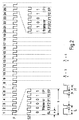
- Fig. 1 shows the signal of the recorded track S1.
- the signal track S1 contains bit information every 40 ms.
- Each frame signal F identifies a self-contained area, the data recorded in the helical tracks.
- the sequence of 25 frame pulses F shown thus comprises the time of 1 second.
- the recorded signal Sy of the first three frame pulses F is a symmetrical rectangular sequence with a pulse-pause ratio of exactly 50%. It is used for synchronization.
- the synchronization bits are followed by 3 control bits C, which represent control information for the overall system.
- the following 19 bits carry information in groups of hours h (4 bits), minutes m (6 bits) and seconds s (6 bits), each counted in binary and protected with one parity bit P (even parity) per group.
- the described sequence of 25 bits is recorded once every second.
- the subsequent data bits of the frame pulses F4 to F25 are characterized by a pulse / pause ratio of 25% in the case of an H bit and 75% in the case of an L bit.
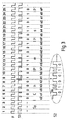
- Track S1 is equal to track S1 recorded in solution 1.
- Track S1 is a low frequency signal
- track S2 is a high frequency signal.
- the low-frequency signal of track S1 which serves as the basic signal, is used in such a way that a symmetrical sequence of three bits is inserted or added symmetrically in front of and behind the edge on each falling edge of track S1.
- the added bits consist of one or two oscillation trains with a pulse-pause ratio of 50%. This ensures that the amplitude reconstruction for positive and negative sequence of a bit is constant in rewinding operation, which facilitates evaluation.
- the bit length for H bits and L bits is the same here, so that the length of the evaluation window is constant for all bits.
- the maximum bit length results from the permissible shift of the low-frequency time code signal. A value of +/- 3 ms will enable clean identification even in rewinding mode.
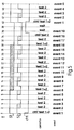
- Fig. 4 shows the basic circuit for recording and regeneration of the signals.
- the left side represents the generation of the signals.
- a microcontroller ⁇ C sets the logical states at out1 and out2 for tracks S1 and S2 together with a time-precise clock OCR.
- Out1 and out2 are synchronized with the clock in a subsequent D flip-flop and are available for recording at Q1 as S1 and at Q2 as S2.
- the reproduction part is shown on the right half of FIG.
- the rectangular signals in1 and in2 are available at the outputs of the amplifiers. This is followed by a multiplexer m, which switches one of these signals at the high-resolution measurement input of a microcontroller ⁇ C in accordance with the predetermined scheme using the signal ctrl.
- This configuration shown is to be used when using a microcontroller ⁇ C, which has a few high-resolution measurement inputs ICR, with which the time between input signal edges can be measured with an accuracy of 250 ns, but which has a large number of normal inputs. If, on the other hand, two of these ICR inputs are available, the lines in1 and in2 must be connected directly to ICR1 and ICR2. The multiplexer m with the control line ctrl can then be omitted. A multiplexing process in the form of a signal Selection in the microcontroller is still possible.
Landscapes
- Engineering & Computer Science (AREA)
- Signal Processing (AREA)
- Signal Processing For Digital Recording And Reproducing (AREA)
- Indexing, Searching, Synchronizing, And The Amount Of Synchronization Travel Of Record Carriers (AREA)
- Television Signal Processing For Recording (AREA)
Applications Claiming Priority (2)
| Application Number | Priority Date | Filing Date | Title |
|---|---|---|---|
| DE4241986A DE4241986A1 (de) | 1992-12-12 | 1992-12-12 | Verfahren zur Schrägspurmagnetbandaufzeichnung |
| DE4241986 | 1992-12-12 |
Publications (3)
| Publication Number | Publication Date |
|---|---|
| EP0602469A2 true EP0602469A2 (fr) | 1994-06-22 |
| EP0602469A3 EP0602469A3 (fr) | 1995-11-29 |
| EP0602469B1 EP0602469B1 (fr) | 2000-04-12 |
Family
ID=6475115
Family Applications (1)
| Application Number | Title | Priority Date | Filing Date |
|---|---|---|---|
| EP93119477A Expired - Lifetime EP0602469B1 (fr) | 1992-12-12 | 1993-12-03 | Méthode et appareil d'enregistrement sur bande magnétique à pistes obliques |
Country Status (7)
| Country | Link |
|---|---|
| US (1) | US5644675A (fr) |
| EP (1) | EP0602469B1 (fr) |
| JP (1) | JP3490484B2 (fr) |
| KR (1) | KR100280574B1 (fr) |
| CN (1) | CN1039948C (fr) |
| DE (2) | DE4241986A1 (fr) |
| ES (1) | ES2145759T3 (fr) |
Cited By (1)
| Publication number | Priority date | Publication date | Assignee | Title |
|---|---|---|---|---|
| EP0913998A4 (fr) * | 1997-04-15 | 1999-05-12 |
Families Citing this family (4)
| Publication number | Priority date | Publication date | Assignee | Title |
|---|---|---|---|---|
| JPH1066036A (ja) * | 1996-08-15 | 1998-03-06 | Oki Electric Ind Co Ltd | Tv方式変換装置 |
| CN1161780C (zh) * | 1999-01-07 | 2004-08-11 | 日本胜利株式会社 | 数据记录方法及装置 |
| JP2001118366A (ja) * | 1999-10-20 | 2001-04-27 | Brother Ind Ltd | 不連続位置検出装置及び検出方法 |
| CN119292964B (zh) * | 2024-12-11 | 2025-03-04 | 成都博宇利华科技有限公司 | 高速缓存的时码标记方法 |
Family Cites Families (14)
| Publication number | Priority date | Publication date | Assignee | Title |
|---|---|---|---|---|
| US3681524A (en) * | 1970-06-16 | 1972-08-01 | Columbia Broadcasting Syst Inc | Multiple frequency time code generator and reader |
| GB1577133A (en) * | 1976-03-19 | 1980-10-22 | Rca Corp | Video information record and playback apparatus |
| US4665431A (en) * | 1982-06-24 | 1987-05-12 | Cooper J Carl | Apparatus and method for receiving audio signals transmitted as part of a television video signal |
| US4516164A (en) * | 1982-10-21 | 1985-05-07 | Stypher Corporation | Apparatus for decoding video address code signals |
| GB2131996A (en) * | 1982-11-30 | 1984-06-27 | George Saint | Data storage devices |
| DE3309029C2 (de) * | 1983-03-14 | 1985-05-15 | Winfried Dipl.-Ing.(FH) 8000 München Walter | Verfahren zum Bestimmen der momentanen Bandlänge eines Videomagnetbandes und nach diesem Verfahren bespielte Videomagnetbänder |
| US4663678A (en) * | 1984-06-18 | 1987-05-05 | Odetics, Inc. | System for writing and reading digital data interspersed with analog audio frequency data on magnetic recording tape |
| JPH0795390B2 (ja) * | 1985-08-07 | 1995-10-11 | 株式会社日立製作所 | 磁気記録再生装置の制御信号記録装置 |
| DE3619359A1 (de) * | 1986-06-09 | 1987-12-10 | Gen Service Electronics Gmbh | Verfahren zum uebertragen eines informationskodes auf der synchronspur eines videobandes, vorrichtung zur durchfuehrung des verfahrens sowie nach dem verfahren hergestelltes videoband |
| JPH0664777B2 (ja) * | 1986-10-03 | 1994-08-22 | シンワ株式会社 | テ−プレコ−ダのテ−プ巻終り検出装置 |
| DE3742469C1 (de) * | 1987-12-15 | 1989-05-24 | Graetz Nokia Gmbh | Videorecorder mit einer Einrichtung zur Aufzeichnung einer zusaetzlichen Steuersignalspur auf ein Videoband |
| CN1049978A (zh) * | 1989-05-03 | 1991-03-20 | 何吉松 | 太空棋 |
| NL9000635A (nl) * | 1990-03-20 | 1991-10-16 | Philips Nv | Digitaal opteken- en weergavesysteem. |
| JP2741112B2 (ja) * | 1991-03-29 | 1998-04-15 | シャープ株式会社 | ディジタル変調方式およびディジタル変調装置 |
-
1992
- 1992-12-12 DE DE4241986A patent/DE4241986A1/de not_active Withdrawn
-
1993
- 1993-12-03 EP EP93119477A patent/EP0602469B1/fr not_active Expired - Lifetime
- 1993-12-03 ES ES93119477T patent/ES2145759T3/es not_active Expired - Lifetime
- 1993-12-03 DE DE59310007T patent/DE59310007D1/de not_active Expired - Fee Related
- 1993-12-09 KR KR1019930026951A patent/KR100280574B1/ko not_active Expired - Fee Related
- 1993-12-11 CN CN93120820A patent/CN1039948C/zh not_active Expired - Fee Related
- 1993-12-13 JP JP31195093A patent/JP3490484B2/ja not_active Expired - Fee Related
-
1995
- 1995-03-27 US US08/410,417 patent/US5644675A/en not_active Expired - Fee Related
Cited By (2)
| Publication number | Priority date | Publication date | Assignee | Title |
|---|---|---|---|---|
| EP0913998A4 (fr) * | 1997-04-15 | 1999-05-12 | ||
| US6546191B1 (en) | 1997-04-15 | 2003-04-08 | Matsushita Electric Industrial Co., Ltd. | Recording-reproducing apparatus for progress TV system |
Also Published As
| Publication number | Publication date |
|---|---|
| EP0602469A3 (fr) | 1995-11-29 |
| US5644675A (en) | 1997-07-01 |
| KR940015974A (ko) | 1994-07-22 |
| CN1039948C (zh) | 1998-09-23 |
| ES2145759T3 (es) | 2000-07-16 |
| JP3490484B2 (ja) | 2004-01-26 |
| JPH06259944A (ja) | 1994-09-16 |
| KR100280574B1 (ko) | 2001-03-02 |
| DE59310007D1 (de) | 2000-05-18 |
| EP0602469B1 (fr) | 2000-04-12 |
| CN1089050A (zh) | 1994-07-06 |
| DE4241986A1 (de) | 1994-06-16 |
Similar Documents
| Publication | Publication Date | Title |
|---|---|---|
| DE2618031C2 (de) | Auswerteschaltung für Binärdaten | |
| DE3825960C2 (fr) | ||
| DE2427225C3 (de) | Schaltungsanordnung zur Demodulation digitaler Information | |
| DE3809179C2 (de) | Verfahren und Vorrichtung zur Aufnahme und Wiedergabe eines digitalen Signals unter Verwendung eines Rotationskopfs | |
| AT389787B (de) | Zeitzaehltaktgenerator | |
| CH619314A5 (fr) | ||
| DE2500696A1 (de) | Verfahren zum unterteilen eines kontinuierlichen signals | |
| DE2841728A1 (de) | Verfahren und schaltungsanordnung zur wiedergabe eines auf magnetband gespeicherten videosignals mit veraenderlicher geschwindigkeit | |
| DE3004799C2 (fr) | ||
| DE2934739C2 (de) | Digitale Servo-Steuerschaltung | |
| DE2140741A1 (de) | Anordnung zur Feststellung des Auf tretens eines Ereignisses | |
| DE3236311A1 (de) | Datensynchronisierer | |
| DE2924695C2 (fr) | ||
| DE69029319T2 (de) | Verfahren und Gerät zur Synchronisation einer Vielzahl von CD-Spielern | |
| EP0602469B1 (fr) | Méthode et appareil d'enregistrement sur bande magnétique à pistes obliques | |
| DE2832337A1 (de) | Informationsaufzeichnungs- und informationswiedergabegeraet | |
| DE2849983A1 (de) | Schaltungsanordnung und verfahren zur automatischen unterscheidung zwischen mehreren in einem zeit-codesignal enthaltenen standardangaben | |
| EP0198841B1 (fr) | Systeme de commande a posteriori pour un magnetophone a enregistrement transversal des voies | |
| DE2912754C2 (fr) | ||
| DE69320509T2 (de) | Verfahren zur seriellen Ausgabe der Bits von neuerschaftenen Synchronisationsdaten oder dergleichen | |
| DE2016447A1 (de) | Schaltung zum mehrspurigen Aufzeichnen und Wiedergeben von Binär-Informationen hoher Bitdichte | |
| EP0872974B1 (fr) | Dispositif de détection de motif d'erreur de bit | |
| DE4343809C2 (de) | Schrägspurmagnetbandaufzeichnungsgerät für digitale Signale mit verschiedenen Betriebsarten | |
| EP0578078B1 (fr) | Procédé pour le suivi de piste dans un enregistreur | |
| DE3225406C2 (fr) |
Legal Events
| Date | Code | Title | Description |
|---|---|---|---|
| PUAI | Public reference made under article 153(3) epc to a published international application that has entered the european phase |
Free format text: ORIGINAL CODE: 0009012 |
|
| AK | Designated contracting states |
Kind code of ref document: A2 Designated state(s): DE ES FR GB IT |
|
| PUAL | Search report despatched |
Free format text: ORIGINAL CODE: 0009013 |
|
| AK | Designated contracting states |
Kind code of ref document: A3 Designated state(s): DE ES FR GB IT |
|
| 17P | Request for examination filed |
Effective date: 19960530 |
|
| 17Q | First examination report despatched |
Effective date: 19961203 |
|
| GRAG | Despatch of communication of intention to grant |
Free format text: ORIGINAL CODE: EPIDOS AGRA |
|
| RTI1 | Title (correction) |
Free format text: METHOD AND APPARATUS FOR RECORDING ON A MAGNETIC TAPE WITH SLANT TRACKS |
|
| GRAG | Despatch of communication of intention to grant |
Free format text: ORIGINAL CODE: EPIDOS AGRA |
|
| GRAG | Despatch of communication of intention to grant |
Free format text: ORIGINAL CODE: EPIDOS AGRA |
|
| GRAH | Despatch of communication of intention to grant a patent |
Free format text: ORIGINAL CODE: EPIDOS IGRA |
|
| GRAH | Despatch of communication of intention to grant a patent |
Free format text: ORIGINAL CODE: EPIDOS IGRA |
|
| GRAA | (expected) grant |
Free format text: ORIGINAL CODE: 0009210 |
|
| ITF | It: translation for a ep patent filed | ||
| AK | Designated contracting states |
Kind code of ref document: B1 Designated state(s): DE ES FR GB IT |
|
| GBT | Gb: translation of ep patent filed (gb section 77(6)(a)/1977) |
Effective date: 20000413 |
|
| REF | Corresponds to: |
Ref document number: 59310007 Country of ref document: DE Date of ref document: 20000518 |
|
| ET | Fr: translation filed | ||
| REG | Reference to a national code |
Ref country code: ES Ref legal event code: FG2A Ref document number: 2145759 Country of ref document: ES Kind code of ref document: T3 |
|
| PLBE | No opposition filed within time limit |
Free format text: ORIGINAL CODE: 0009261 |
|
| STAA | Information on the status of an ep patent application or granted ep patent |
Free format text: STATUS: NO OPPOSITION FILED WITHIN TIME LIMIT |
|
| 26N | No opposition filed | ||
| REG | Reference to a national code |
Ref country code: GB Ref legal event code: IF02 |
|
| PGFP | Annual fee paid to national office [announced via postgrant information from national office to epo] |
Ref country code: GB Payment date: 20051110 Year of fee payment: 13 |
|
| PGFP | Annual fee paid to national office [announced via postgrant information from national office to epo] |
Ref country code: DE Payment date: 20051216 Year of fee payment: 13 |
|
| PGFP | Annual fee paid to national office [announced via postgrant information from national office to epo] |
Ref country code: FR Payment date: 20051222 Year of fee payment: 13 |
|
| PGFP | Annual fee paid to national office [announced via postgrant information from national office to epo] |
Ref country code: ES Payment date: 20051227 Year of fee payment: 13 |
|
| PGFP | Annual fee paid to national office [announced via postgrant information from national office to epo] |
Ref country code: IT Payment date: 20061231 Year of fee payment: 14 |
|
| PG25 | Lapsed in a contracting state [announced via postgrant information from national office to epo] |
Ref country code: DE Free format text: LAPSE BECAUSE OF NON-PAYMENT OF DUE FEES Effective date: 20070703 |
|
| GBPC | Gb: european patent ceased through non-payment of renewal fee |
Effective date: 20061203 |
|
| REG | Reference to a national code |
Ref country code: FR Ref legal event code: ST Effective date: 20070831 |
|
| PG25 | Lapsed in a contracting state [announced via postgrant information from national office to epo] |
Ref country code: GB Free format text: LAPSE BECAUSE OF NON-PAYMENT OF DUE FEES Effective date: 20061203 |
|
| REG | Reference to a national code |
Ref country code: ES Ref legal event code: FD2A Effective date: 20061204 |
|
| PG25 | Lapsed in a contracting state [announced via postgrant information from national office to epo] |
Ref country code: FR Free format text: LAPSE BECAUSE OF NON-PAYMENT OF DUE FEES Effective date: 20070102 Ref country code: ES Free format text: LAPSE BECAUSE OF NON-PAYMENT OF DUE FEES Effective date: 20061204 |
|
| PG25 | Lapsed in a contracting state [announced via postgrant information from national office to epo] |
Ref country code: IT Free format text: LAPSE BECAUSE OF NON-PAYMENT OF DUE FEES Effective date: 20071203 |