EP0602530A2 - Procédé pour fabriquer un joint étanche au vide entre une partie céramique et une partie métallique, notamment pour des récipients et des lampes à décharge - Google Patents
Procédé pour fabriquer un joint étanche au vide entre une partie céramique et une partie métallique, notamment pour des récipients et des lampes à décharge Download PDFInfo
- Publication number
- EP0602530A2 EP0602530A2 EP93119796A EP93119796A EP0602530A2 EP 0602530 A2 EP0602530 A2 EP 0602530A2 EP 93119796 A EP93119796 A EP 93119796A EP 93119796 A EP93119796 A EP 93119796A EP 0602530 A2 EP0602530 A2 EP 0602530A2
- Authority
- EP
- European Patent Office
- Prior art keywords
- ceramic
- discharge vessel
- tube
- lamp
- vacuum
- Prior art date
- Legal status (The legal status is an assumption and is not a legal conclusion. Google has not performed a legal analysis and makes no representation as to the accuracy of the status listed.)
- Granted
Links
Images


Classifications
-
- H—ELECTRICITY
- H01—ELECTRIC ELEMENTS
- H01J—ELECTRIC DISCHARGE TUBES OR DISCHARGE LAMPS
- H01J5/00—Details relating to vessels or to leading-in conductors common to two or more basic types of discharge tubes or lamps
- H01J5/32—Seals for leading-in conductors
- H01J5/40—End-disc seals, e.g. flat header
- H01J5/42—End-disc seals, e.g. flat header using intermediate part
-
- C—CHEMISTRY; METALLURGY
- C04—CEMENTS; CONCRETE; ARTIFICIAL STONE; CERAMICS; REFRACTORIES
- C04B—LIME, MAGNESIA; SLAG; CEMENTS; COMPOSITIONS THEREOF, e.g. MORTARS, CONCRETE OR LIKE BUILDING MATERIALS; ARTIFICIAL STONE; CERAMICS; REFRACTORIES; TREATMENT OF NATURAL STONE
- C04B37/00—Joining burned ceramic articles with other burned ceramic articles or other articles by heating
- C04B37/02—Joining burned ceramic articles with other burned ceramic articles or other articles by heating with metallic articles
- C04B37/023—Joining burned ceramic articles with other burned ceramic articles or other articles by heating with metallic articles characterised by the interlayer used
- C04B37/025—Joining burned ceramic articles with other burned ceramic articles or other articles by heating with metallic articles characterised by the interlayer used consisting of glass or ceramic material
-
- H—ELECTRICITY
- H01—ELECTRIC ELEMENTS
- H01J—ELECTRIC DISCHARGE TUBES OR DISCHARGE LAMPS
- H01J5/00—Details relating to vessels or to leading-in conductors common to two or more basic types of discharge tubes or lamps
- H01J5/20—Seals between parts of vessels
- H01J5/22—Vacuum-tight joints between parts of vessel
-
- H—ELECTRICITY
- H01—ELECTRIC ELEMENTS
- H01J—ELECTRIC DISCHARGE TUBES OR DISCHARGE LAMPS
- H01J61/00—Gas-discharge or vapour-discharge lamps
- H01J61/02—Details
- H01J61/36—Seals between parts of vessels; Seals for leading-in conductors; Leading-in conductors
- H01J61/366—Seals for leading-in conductors
-
- C—CHEMISTRY; METALLURGY
- C04—CEMENTS; CONCRETE; ARTIFICIAL STONE; CERAMICS; REFRACTORIES
- C04B—LIME, MAGNESIA; SLAG; CEMENTS; COMPOSITIONS THEREOF, e.g. MORTARS, CONCRETE OR LIKE BUILDING MATERIALS; ARTIFICIAL STONE; CERAMICS; REFRACTORIES; TREATMENT OF NATURAL STONE
- C04B2237/00—Aspects relating to ceramic laminates or to joining of ceramic articles with other articles by heating
- C04B2237/02—Aspects relating to interlayers, e.g. used to join ceramic articles with other articles by heating
- C04B2237/04—Ceramic interlayers
- C04B2237/06—Oxidic interlayers
- C04B2237/064—Oxidic interlayers based on alumina or aluminates
-
- C—CHEMISTRY; METALLURGY
- C04—CEMENTS; CONCRETE; ARTIFICIAL STONE; CERAMICS; REFRACTORIES
- C04B—LIME, MAGNESIA; SLAG; CEMENTS; COMPOSITIONS THEREOF, e.g. MORTARS, CONCRETE OR LIKE BUILDING MATERIALS; ARTIFICIAL STONE; CERAMICS; REFRACTORIES; TREATMENT OF NATURAL STONE
- C04B2237/00—Aspects relating to ceramic laminates or to joining of ceramic articles with other articles by heating
- C04B2237/30—Composition of layers of ceramic laminates or of ceramic or metallic articles to be joined by heating, e.g. Si substrates
- C04B2237/32—Ceramic
- C04B2237/34—Oxidic
- C04B2237/343—Alumina or aluminates
-
- C—CHEMISTRY; METALLURGY
- C04—CEMENTS; CONCRETE; ARTIFICIAL STONE; CERAMICS; REFRACTORIES
- C04B—LIME, MAGNESIA; SLAG; CEMENTS; COMPOSITIONS THEREOF, e.g. MORTARS, CONCRETE OR LIKE BUILDING MATERIALS; ARTIFICIAL STONE; CERAMICS; REFRACTORIES; TREATMENT OF NATURAL STONE
- C04B2237/00—Aspects relating to ceramic laminates or to joining of ceramic articles with other articles by heating
- C04B2237/30—Composition of layers of ceramic laminates or of ceramic or metallic articles to be joined by heating, e.g. Si substrates
- C04B2237/40—Metallic
- C04B2237/403—Refractory metals
-
- C—CHEMISTRY; METALLURGY
- C04—CEMENTS; CONCRETE; ARTIFICIAL STONE; CERAMICS; REFRACTORIES
- C04B—LIME, MAGNESIA; SLAG; CEMENTS; COMPOSITIONS THEREOF, e.g. MORTARS, CONCRETE OR LIKE BUILDING MATERIALS; ARTIFICIAL STONE; CERAMICS; REFRACTORIES; TREATMENT OF NATURAL STONE
- C04B2237/00—Aspects relating to ceramic laminates or to joining of ceramic articles with other articles by heating
- C04B2237/50—Processing aspects relating to ceramic laminates or to the joining of ceramic articles with other articles by heating
- C04B2237/70—Forming laminates or joined articles comprising layers of a specific, unusual thickness
- C04B2237/706—Forming laminates or joined articles comprising layers of a specific, unusual thickness of one or more of the metallic layers or articles
-
- C—CHEMISTRY; METALLURGY
- C04—CEMENTS; CONCRETE; ARTIFICIAL STONE; CERAMICS; REFRACTORIES
- C04B—LIME, MAGNESIA; SLAG; CEMENTS; COMPOSITIONS THEREOF, e.g. MORTARS, CONCRETE OR LIKE BUILDING MATERIALS; ARTIFICIAL STONE; CERAMICS; REFRACTORIES; TREATMENT OF NATURAL STONE
- C04B2237/00—Aspects relating to ceramic laminates or to joining of ceramic articles with other articles by heating
- C04B2237/50—Processing aspects relating to ceramic laminates or to the joining of ceramic articles with other articles by heating
- C04B2237/76—Forming laminates or joined articles comprising at least one member in the form other than a sheet or disc, e.g. two tubes or a tube and a sheet or disc
- C04B2237/765—Forming laminates or joined articles comprising at least one member in the form other than a sheet or disc, e.g. two tubes or a tube and a sheet or disc at least one member being a tube
-
- C—CHEMISTRY; METALLURGY
- C04—CEMENTS; CONCRETE; ARTIFICIAL STONE; CERAMICS; REFRACTORIES
- C04B—LIME, MAGNESIA; SLAG; CEMENTS; COMPOSITIONS THEREOF, e.g. MORTARS, CONCRETE OR LIKE BUILDING MATERIALS; ARTIFICIAL STONE; CERAMICS; REFRACTORIES; TREATMENT OF NATURAL STONE
- C04B2237/00—Aspects relating to ceramic laminates or to joining of ceramic articles with other articles by heating
- C04B2237/50—Processing aspects relating to ceramic laminates or to the joining of ceramic articles with other articles by heating
- C04B2237/84—Joining of a first substrate with a second substrate at least partially inside the first substrate, where the bonding area is at the inside of the first substrate, e.g. one tube inside another tube
Definitions
- the invention relates to a method for producing a vacuum-tight seal between a ceramic and a metallic partner, in particular for use in the manufacture of a discharge vessel for a lamp, and to discharge vessels and lamps produced therewith.
- the invention relates predominantly, but not exclusively, to the production of ceramic discharge vessels for high-pressure discharge lamps.
- Such vessels are usually used in high pressure sodium lamps.
- Such lamps usually have a quartz glass discharge vessel. Efforts are currently being made to improve the color rendering of these lamps. The one you need higher operating temperature can be achieved with a ceramic discharge vessel. Typical power levels are 50 - 250 W.
- the ends of the elongated discharge vessel are usually closed with cylindrical ceramic end plugs into which a metal current feedthrough is inserted in the middle.
- a particularly simple way of filling and evacuating the discharge vessel is that one of the two niobium tubes has a small opening in the vicinity of the electrode shaft attached to the tube inside the discharge vessel, so that the amalgam and the inert gas can be evacuated and filled through this opening is (GB-PS 2 072 939).
- the end of the niobium tube which protrudes from the outside is sealed gas-tight by a pinch with subsequent welding.
- the opening in the vicinity of the electrode shaft always remains continuous in order to provide a connection between the interior of the discharge vessel during operation and ensure that the inside of the feed-through tube acts as a cold spot.
- EP-PA 92 114 227.9 (A. 54 (3) EPC) describes a high-pressure lamp with a ceramic discharge vessel, in which a tubular bushing made of molybdenum or the like. is sintered directly into a ceramic end plug.
- PCT / DE 92/00 372 (A. 54 (3) EPC) describes a filling process for metal halide discharge lamps with a ceramic discharge vessel, in which an opening in the leadthrough or in the end plug or is used as a filling hole in the discharge vessel.
- the present application expressly refers to the content of these two earlier rights.
- the method according to the invention which can be applied to lamps and other electrical devices, in particular discharge tubes, avoids the disadvantages of the prior art discussed above.
- the ceramic container is sealed in several steps with the help of an additional part, the open pipe.
- It advantageously consists of molybdenum or its alloy.
- a pipe made of another metal with similar properties to molybdenum (low expansion coefficient with good corrosion resistance) is also suitable (e.g. tungsten or rhenium), but here the practical implementation is more complex.
- tungsten or rhenium e.g. tungsten or rhenium
- the molybdenum tube is sintered directly into an opening in the ceramic container.
- a correspondingly shaped integral end of the container is suitable as the sealing means.
- a separate sealing means in the form of an end plug is frequently used.
- the end plug usually consists, similar to the ceramic container, of a translucent ceramic, primarily Al2O3 with the use of dopants. In this case, the expansion coefficient of the ceramic container (generally about 6.5 to 9 x 10 ⁇ 6 K ⁇ 1) and the end plug are close together.
- a material can also be used - possibly containing several components - which consists mainly of ceramic but contains up to 40% additives that reduce the coefficient of expansion so that it lies between that of the ceramic and metallic partner. Examples of this can be found in PCT / DE 92/00372.
- a metallic partner is inserted into the sintered open molybdenum tube. It is often a bushing as used in discharge lamps and tubes.
- the outer dimensions of this metallic partner are adapted to the molybdenum tube, i.e. it can either be a pipe or a pin, which may also be composed of several parts. It is made of a material whose coefficient of thermal expansion can be significantly (up to 60%, possibly even more) smaller than that of the container.
- the material should advantageously be corrosion-resistant to metal halides and sodium.
- molybdenum, tungsten and rhenium come into consideration, whose thermal expansion coefficients are around 4 to 5 x 10 ⁇ 6 K ⁇ 1.
- the coefficient of the metallic partner corresponds approximately to that of the molybdenum tube, since in a third step the sealing of the opening is accomplished by the metallic partner with the molybdenum tube in the area of the outside (in the case of a passage for discharge lamps and tubes) That is, the end of the molybdenum tube remote from the discharge is connected, in particular welded.
- the advantage is that the outer end is easily accessible and the quality of the connection can be monitored reliably. If materials with very different expansion coefficients were bonded to one another, the seam would be exposed to a high mechanical load under thermal stress, which would lead to premature leakage of the seal.
- the diameter of the electrode must be smaller than the inside diameter of the molybdenum tube.
- the electrode system must be vacuum-sealed to ensure that the third process step completes the sealing. There are basically two ways to do this.
- the safest option with regard to the sealing is the use of a solid pin as a leadthrough, the electrode being attached in any way to the end of the pin on the discharge side.
- the material consumption is relatively high here.
- An alternative is to use a tube which, for metal halide lamps, advantageously at its discharge end, is sealed in a vacuum-tight manner, for example by the electrode shaft.
- a bushing composed of a tube and a pin section.
- a tube with an inserted pin can also be considered; this can advantageously be used immediately as an external contacting aid for the external power supply.
- the method according to the invention also offers a simple possibility of charging the ceramic container with filler material through the still open molybdenum tube.
- these are inert gases, in particular noble gases (xenon, argon) and / or mercury, which are required to initiate or maintain a discharge between two electrodes placed in the ceramic container.
- Additives such as sodium (amalgamated with mercury) or metal halides (usually in solid form) can be easily and reliably introduced through the natural opening of the molybdenum tube.
- Molybdenum tubes with an outer diameter of approx. 1.3 to 2.0 mm and an inner diameter of approx. 0.8 to 1.5 mm corresponding to a wall thickness of 0.1 to 0.3 mm have proven particularly useful. These dimensions ensure the necessary flexibility for permanent direct sintering and a sufficiently large filling opening for the filling substances.
- the particular advantage of such a lamp is that there is no need for any kind of solder (glass or metal) or fused ceramic.
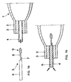
- the interior of the discharge vessel 1 is evacuated through the open molybdenum tube 4 (provided that the second, invisible end is already sealed in a vacuum-tight manner). Then inert ignition gas (argon or xenon) is filled into the discharge vessel 1. In addition, appropriately portioned mercury and metal halides (the latter in the form of pills) and possibly additional metals (in the form of wire pins) are introduced through the tube 4.
- the discharge vessel is on previously closed end (not visible) cooled with liquid nitrogen, the open end 2 being oriented upwards.
- a preassembled electrode system 5 is now immediately inserted into the molybdenum tube 4 with an inner diameter of 1.3 mm (FIG. 1a). It consists of a molybdenum (or also tungsten) pin 6 with a diameter of approximately 1.2 mm, the discharge-side end of which has a projection 7 to which an electrode core pin 8 with a diameter of 0.5 mm is welded.
- the core pin 8 consists of tungsten.
- a helix 9 is attached to it, the outside diameter of which does not exceed that of the molybdenum pin 6.
- the molybdenum pin 6 advantageously has, at the end opposite the projection 7, a stop (not visible) projecting beyond the inside diameter of the molybdenum tube 4, e.g. in the form of three lugs, which are evenly distributed over the circumference of the pin 6.
- the stop ensures that the electrode spacing is maintained and enables the pen to be temporarily held in place.
- the end 2 is finally closed by sealing the annular gap between the two parts at the outer end of tube 4 and pin 6 by means of laser welding (arrows) (FIG. 1b).
- the rest of the electrode system and in particular the discharge vessel are covered by this gentle heat treatment not warmed up appreciably. Therefore, the type of sealing according to the invention can also be used in particular with very small vessel dimensions (for example corresponding to a power level of 50 W or less) and / or for filling systems with high filling gas pressure (for example xenon instead of argon).
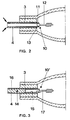
- FIG. 2 An alternative electrode system 10 is shown in FIG. 2. It consists of a molybdenum tube 11 as a leadthrough, which has an inner diameter of 1.0 mm with an outer diameter of 1.2 mm. The tube 11 protrudes somewhat on the discharge side from the outer molybdenum tube 4. At this end, a core pin 12 is attached, the diameter (0.5 mm) of which is considerably smaller than that of the inner diameter of the molybdenum tube 11. For this purpose, the end of the core pin 12 is melted back so far that it forms a ball 13 with a diameter which is adapted to the inside diameter of the molybdenum tube 11. In this embodiment, the electrode system 10 is sealed in that the ball end 13 is welded to the molybdenum tube 11. The bushing 11 is fastened to the outer molybdenum tube 4 again in a manner similar to that in the first exemplary embodiment by laser welding (arrow) at the outer end.
- the leadthrough 14 is composed of two sections 15, 16 made of molybdenum.
- the discharge-side section 15 is a tube in which a core pin 17 is fastened to the inner wall.
- the discharge distal portion 16 is a pin that is blunt with the Pipe section 15 is welded.
- the core pin 17 is arranged somewhat outside the lamp axis in order to leave an opening which connects the tube section 15, which acts as an amalgam reservoir, to the interior of the discharge vessel.
- the front part of the core pin 17 is advantageously angled towards the axis in order to facilitate the insertion of the electrode system 10 'into the molybdenum tube 4 and to align the discharge-side end of the electrode exactly in the axis.
- FIG. 4 A further embodiment of the electrode system 18 is shown in FIG. 4.
- a contacting aid 19 in the form of a molybdenum pin is attached to the tubular bushing 11 (corresponding to FIG. 2) in order to facilitate the attachment of an external power supply.
- This contacting aid 19 can advantageously also be welded in when the bushing 11 and outer molybdenum tube 4 are sealed (arrow).
- This provides the electrode system 18 with an additional seal, which further extends the service life.
- the first sealing takes place, as already shown with reference to FIG. 2, by fastening the spherical end 13 of the core pin 12 in the tubular bushing 11.
- the outer contacting aid can also be realized in that the pin section 20 is extended beyond the end of the molybdenum tube 4 (FIG. 5).
- the invention is not limited by the exemplary embodiments shown.
- the end 24a of a continuous pin-shaped bushing 24 can be used as a contacting aid for the outer Power supply lines 25 can be extended beyond the end of the molybdenum tube 4 (FIG. 6).
- the discharge vessels described here are usually used in an outer bulb 21 made of tempered glass (FIG. 6). It has the shape of a cylinder. Its two ends are closed with ceramic bases 22.
- a lamp 23 constructed in this way with a metal halide filling is distinguished in particular by its good color rendering (Ra> 90).
Landscapes
- Chemical & Material Sciences (AREA)
- Engineering & Computer Science (AREA)
- Ceramic Engineering (AREA)
- Materials Engineering (AREA)
- Structural Engineering (AREA)
- Organic Chemistry (AREA)
- Vessels And Coating Films For Discharge Lamps (AREA)
- Ceramic Products (AREA)
- Manufacture Of Electron Tubes, Discharge Lamp Vessels, Lead-In Wires, And The Like (AREA)
Applications Claiming Priority (2)
| Application Number | Priority Date | Filing Date | Title |
|---|---|---|---|
| DE4242122A DE4242122A1 (de) | 1992-12-14 | 1992-12-14 | Verfahren zur Herstellung einer vakuumdichten Abdichtung zwischen einem keramischen und einem metallischen Partner, insbesondere zur Anwendung bei der Herstellung eines Entladungsgefäßes für eine Lampe, sowie damit hergestellte Entladungsgefäße und Lampen |
| DE4242122 | 1992-12-14 |
Publications (3)
| Publication Number | Publication Date |
|---|---|
| EP0602530A2 true EP0602530A2 (fr) | 1994-06-22 |
| EP0602530A3 EP0602530A3 (fr) | 1995-01-04 |
| EP0602530B1 EP0602530B1 (fr) | 1999-03-03 |
Family
ID=6475217
Family Applications (1)
| Application Number | Title | Priority Date | Filing Date |
|---|---|---|---|
| EP93119796A Expired - Lifetime EP0602530B1 (fr) | 1992-12-14 | 1993-12-08 | Procédé pour fabriquer un joint étanche au vide pour un récipient céramique et une lampe à décharge |
Country Status (6)
| Country | Link |
|---|---|
| US (1) | US5552670A (fr) |
| EP (1) | EP0602530B1 (fr) |
| JP (1) | JPH06318435A (fr) |
| CN (1) | CN1090088A (fr) |
| DE (2) | DE4242122A1 (fr) |
| HU (1) | HU214424B (fr) |
Cited By (2)
| Publication number | Priority date | Publication date | Assignee | Title |
|---|---|---|---|---|
| US6066918A (en) * | 1995-01-13 | 2000-05-23 | Ngk Insulators, Ltd. | High pressure discharge lamp with an improved sealing system and method of producing the same |
| WO2002028575A1 (fr) * | 2000-10-03 | 2002-04-11 | Ngk Insulators, Ltd. | Tube metallique sans soudure et son procede de production |
Families Citing this family (54)
| Publication number | Priority date | Publication date | Assignee | Title |
|---|---|---|---|---|
| US5621275A (en) * | 1995-08-01 | 1997-04-15 | Osram Sylvania Inc. | Arc tube for electrodeless lamp |
| JP3151166B2 (ja) | 1996-05-16 | 2001-04-03 | 日本碍子株式会社 | 高圧放電灯およびその製造方法 |
| JP3264189B2 (ja) * | 1996-10-03 | 2002-03-11 | 松下電器産業株式会社 | 高圧金属蒸気放電ランプ |
| US5834897A (en) * | 1997-05-02 | 1998-11-10 | Osram Sylvania Inc. | Lamp with centered electrode or in-lead |
| US5861714A (en) * | 1997-06-27 | 1999-01-19 | Osram Sylvania Inc. | Ceramic envelope device, lamp with such a device, and method of manufacture of such devices |
| DE19727430A1 (de) * | 1997-06-27 | 1999-01-07 | Patent Treuhand Ges Fuer Elektrische Gluehlampen Mbh | Metallhalogenidlampe mit keramischem Entladungsgefäß |
| JP4316699B2 (ja) * | 1997-07-25 | 2009-08-19 | ハリソン東芝ライティング株式会社 | 高圧放電ランプおよび照明装置 |
| DE69822058D1 (de) * | 1997-09-19 | 2004-04-08 | Matsushita Electric Industrial Co Ltd | Hochdruckentladungslampe und Verfahren zur Herstellung derselben |
| JP3628854B2 (ja) * | 1997-11-14 | 2005-03-16 | 日本碍子株式会社 | 高圧放電灯及びその製造方法 |
| US6375533B1 (en) * | 1998-03-05 | 2002-04-23 | Ushiodenki Kabushiki Kaisha | Electricity lead-in body for bulb and method for manufacturing the same |
| US6646379B1 (en) | 1998-12-25 | 2003-11-11 | Matsushita Electric Industrial Co., Ltd. | Metal vapor discharge lamp having cermet lead-in with improved luminous efficiency and flux rise time |
| JP3450751B2 (ja) * | 1998-08-26 | 2003-09-29 | 日本碍子株式会社 | 接合体、高圧放電灯およびその製造方法 |
| US6635993B1 (en) | 1998-08-26 | 2003-10-21 | Ngk Insulators, Ltd. | Joined bodies, high-pressure discharge lamps and a method for manufacturing the same |
| JP3238909B2 (ja) * | 1999-05-24 | 2001-12-17 | 松下電器産業株式会社 | メタルハライドランプ |
| JP3233355B2 (ja) | 1999-05-25 | 2001-11-26 | 松下電器産業株式会社 | メタルハライドランプ |
| JP3177230B2 (ja) | 1999-05-25 | 2001-06-18 | 松下電子工業株式会社 | 金属蒸気放電ランプ |
| EP1205963B1 (fr) * | 2000-11-07 | 2012-01-18 | Panasonic Corporation | Lampe à décharge à haute pression et tube à arc |
| US6528945B2 (en) | 2001-02-02 | 2003-03-04 | Matsushita Research And Development Laboratories Inc | Seal for ceramic metal halide discharge lamp |
| DE10135235C2 (de) * | 2001-07-24 | 2003-05-28 | Forschungszentrum Juelich Gmbh | Verfahren zur Herstellung einer gasdichten Verbindung zwischen einem metallischen und einem keramischen Substrat |
| US6758386B2 (en) | 2001-09-18 | 2004-07-06 | The Boeing Company | Method of joining ceramic matrix composites and metals |
| JP3907041B2 (ja) * | 2001-10-11 | 2007-04-18 | 日本碍子株式会社 | 高圧放電灯用放電管および高圧放電灯 |
| JP3960796B2 (ja) * | 2001-12-27 | 2007-08-15 | 日本碍子株式会社 | 接合体、高圧放電灯用組み立て体および高圧放電灯 |
| JP3709560B2 (ja) * | 2002-01-21 | 2005-10-26 | 日本碍子株式会社 | 高圧放電灯用組み立て体および高圧放電灯 |
| US6744206B2 (en) * | 2002-02-25 | 2004-06-01 | Matsushita Electric Industrial Co., Ltd. | Metal halide lamp with reduced change in color temperature |
| JP3922452B2 (ja) * | 2002-05-10 | 2007-05-30 | 日本碍子株式会社 | 接合体、高圧放電灯用組み立て体および高圧放電灯 |
| US6856091B2 (en) * | 2002-06-24 | 2005-02-15 | Matsushita Electric Industrial Co., Ltd. | Seal for ceramic metal halide discharge lamp chamber |
| US20040112630A1 (en) * | 2002-12-13 | 2004-06-17 | Taiwan Maeden Co., Ltd. | Sound signal wire and process for enhancing rigidity thereof |
| US6888312B2 (en) | 2002-12-13 | 2005-05-03 | Welch Allyn, Inc. | Metal halide lamp for curing adhesives |
| US7839089B2 (en) * | 2002-12-18 | 2010-11-23 | General Electric Company | Hermetical lamp sealing techniques and lamp having uniquely sealed components |
| US7215081B2 (en) * | 2002-12-18 | 2007-05-08 | General Electric Company | HID lamp having material free dosing tube seal |
| US7132797B2 (en) * | 2002-12-18 | 2006-11-07 | General Electric Company | Hermetical end-to-end sealing techniques and lamp having uniquely sealed components |
| US7525252B2 (en) | 2002-12-27 | 2009-04-28 | General Electric Company | Sealing tube material for high pressure short-arc discharge lamps |
| JP2005183164A (ja) * | 2003-12-19 | 2005-07-07 | Koito Mfg Co Ltd | 放電ランプ装置用アークチューブ |
| DE102004015467B4 (de) * | 2004-03-26 | 2007-12-27 | W.C. Heraeus Gmbh | Elektrodensystem mit einer Stromdurchführung durch ein Keramikbauteil |
| CN1969366B (zh) * | 2004-06-14 | 2011-06-08 | 皇家飞利浦电子股份有限公司 | 陶瓷金属卤化物放电灯 |
| US20060001346A1 (en) * | 2004-06-30 | 2006-01-05 | Vartuli James S | System and method for design of projector lamp |
| US7358666B2 (en) | 2004-09-29 | 2008-04-15 | General Electric Company | System and method for sealing high intensity discharge lamps |
| JP2006283077A (ja) * | 2005-03-31 | 2006-10-19 | Ngk Insulators Ltd | 複合体 |
| JP4587216B2 (ja) * | 2005-03-31 | 2010-11-24 | 日本碍子株式会社 | 放電灯の支持構造および照明装置 |
| US7852006B2 (en) | 2005-06-30 | 2010-12-14 | General Electric Company | Ceramic lamp having molybdenum-rhenium end cap and systems and methods therewith |
| US7615929B2 (en) | 2005-06-30 | 2009-11-10 | General Electric Company | Ceramic lamps and methods of making same |
| US7432657B2 (en) * | 2005-06-30 | 2008-10-07 | General Electric Company | Ceramic lamp having shielded niobium end cap and systems and methods therewith |
| US7378799B2 (en) * | 2005-11-29 | 2008-05-27 | General Electric Company | High intensity discharge lamp having compliant seal |
| JP4739973B2 (ja) * | 2006-02-14 | 2011-08-03 | スタンレー電気株式会社 | 高圧放電ランプ |
| JP2008027698A (ja) * | 2006-07-20 | 2008-02-07 | Osram-Melco Ltd | 超高圧水銀ランプ |
| JP2010514125A (ja) * | 2006-12-20 | 2010-04-30 | コーニンクレッカ フィリップス エレクトロニクス エヌ ヴィ | メタルハライドランプ及びこのようなランプのためのセラミックバーナ |
| US8299709B2 (en) * | 2007-02-05 | 2012-10-30 | General Electric Company | Lamp having axially and radially graded structure |
| US8053990B2 (en) * | 2007-09-20 | 2011-11-08 | General Electric Company | High intensity discharge lamp having composite leg |
| JP5112025B2 (ja) * | 2007-11-28 | 2013-01-09 | 株式会社小糸製作所 | 車輌用放電灯 |
| US7973478B2 (en) * | 2007-11-29 | 2011-07-05 | Osram Gesellschaft mit beschränkter Haftung | Electrode rod holder in a high-pressure discharge lamp |
| US20100026181A1 (en) * | 2008-08-01 | 2010-02-04 | Osram Sylvania Inc. | Ceramic discharge vessel and method of making same |
| US8710742B2 (en) * | 2011-07-06 | 2014-04-29 | Osram Sylvania Inc. | Metal halide lamps with fast run-up and methods of operating the same |
| US9831058B2 (en) * | 2015-01-21 | 2017-11-28 | Varex Imaging Corporation | Vacuum assemblies and methods of formation |
| CN113140377B (zh) * | 2021-03-17 | 2022-05-31 | 中国电子科技集团公司第二十九研究所 | 一种大尺寸陶瓷封装界面结构 |
Family Cites Families (10)
| Publication number | Priority date | Publication date | Assignee | Title |
|---|---|---|---|---|
| BE795680A (fr) * | 1972-02-21 | 1973-08-20 | Philips Nv | Lampe a decharge a haute pression, munie d'un conducteur de traversee metallique |
| NL174682C (nl) * | 1974-11-14 | 1985-01-16 | Philips Nv | Elektrische ontladingslamp. |
| GB1465212A (en) * | 1975-05-12 | 1977-02-23 | Gen Electric | Electric discharge lamps |
| NL7612120A (nl) * | 1976-11-02 | 1978-05-05 | Philips Nv | Elektrische gasontladingslamp. |
| HU178836B (en) * | 1980-02-11 | 1982-07-28 | Egyesuelt Izzzolampa Es Villam | Electric discharge lamp of ceramic bulb |
| US4342938A (en) * | 1980-03-31 | 1982-08-03 | General Electric Company | Universal burning ceramic lamp |
| NL8200783A (nl) * | 1982-02-26 | 1983-09-16 | Philips Nv | Hogedrukontladingslamp. |
| US4545799A (en) * | 1983-09-06 | 1985-10-08 | Gte Laboratories Incorporated | Method of making direct seal between niobium and ceramics |
| US5208509A (en) * | 1988-05-13 | 1993-05-04 | Gte Products Corporation | Arc tube for high pressure metal vapor discharge lamp |
| DE9112690U1 (de) * | 1991-10-11 | 1991-12-05 | Patent-Treuhand-Gesellschaft für elektrische Glühlampen mbH, 8000 München | Hochdruckentladungslampe |
-
1992
- 1992-12-14 DE DE4242122A patent/DE4242122A1/de not_active Withdrawn
-
1993
- 1993-12-01 US US08/160,615 patent/US5552670A/en not_active Expired - Lifetime
- 1993-12-08 DE DE59309411T patent/DE59309411D1/de not_active Expired - Lifetime
- 1993-12-08 JP JP5340208A patent/JPH06318435A/ja active Pending
- 1993-12-08 EP EP93119796A patent/EP0602530B1/fr not_active Expired - Lifetime
- 1993-12-11 CN CN93112862A patent/CN1090088A/zh active Pending
- 1993-12-13 HU HU9303567A patent/HU214424B/hu not_active IP Right Cessation
Cited By (4)
| Publication number | Priority date | Publication date | Assignee | Title |
|---|---|---|---|---|
| US6066918A (en) * | 1995-01-13 | 2000-05-23 | Ngk Insulators, Ltd. | High pressure discharge lamp with an improved sealing system and method of producing the same |
| US6139386A (en) * | 1995-01-13 | 2000-10-31 | Ngk Insulators, Ltd. | High pressure discharge lamp with an improved sealing system and method of producing the same |
| EP0751549B1 (fr) * | 1995-01-13 | 2003-08-06 | Ngk Insulators, Ltd. | Lampe a decharge haute pression et procede de production correspondant |
| WO2002028575A1 (fr) * | 2000-10-03 | 2002-04-11 | Ngk Insulators, Ltd. | Tube metallique sans soudure et son procede de production |
Also Published As
| Publication number | Publication date |
|---|---|
| EP0602530B1 (fr) | 1999-03-03 |
| JPH06318435A (ja) | 1994-11-15 |
| US5552670A (en) | 1996-09-03 |
| HU214424B (hu) | 1998-03-30 |
| DE59309411D1 (de) | 1999-04-08 |
| EP0602530A3 (fr) | 1995-01-04 |
| HUT67663A (en) | 1995-04-28 |
| CN1090088A (zh) | 1994-07-27 |
| DE4242122A1 (de) | 1994-06-16 |
Similar Documents
| Publication | Publication Date | Title |
|---|---|---|
| EP0602530B1 (fr) | Procédé pour fabriquer un joint étanche au vide pour un récipient céramique et une lampe à décharge | |
| EP0607149B1 (fr) | Procede pour la fabrication d'une lampe a decharge a halogenure de metal avec recipient de decharge en ceramique | |
| DE69402848T2 (de) | Keramisches entladungsgefäss und verfahren zu dessen herstellung | |
| EP0570772B1 (fr) | Lampe à décharge à haute pression | |
| EP0887839B1 (fr) | Lampe à halogénure métallique avec enveloppe céramique | |
| EP0528427B1 (fr) | Lampe à décharge à haute pression | |
| EP0887840B1 (fr) | Lampe à halogénure métallique avec enveloppe céramique | |
| EP0887841B1 (fr) | Lampe à halogénure métallique avec enveloppe céramique | |
| EP0602529B1 (fr) | Lampe de décharge à haute pression ayant un récipient céramique de décharge | |
| DE2641880C2 (fr) | ||
| EP2020018A1 (fr) | Lampe à décharge à haute pression | |
| EP0573880A1 (fr) | Lampe à décharge haute pression | |
| DE9012200U1 (de) | Hochdruckentladungslampe | |
| EP0639853A1 (fr) | Lampe à décharge à haute pression avec récipient à décharge en céramique | |
| DE20106002U1 (de) | Metallhalogenidlampe mit keramischem Entladungsgefäß | |
| DE2209805A1 (de) | Metalldampfhochdruckentladungslampe | |
| EP1351278B1 (fr) | Lampe à halogénure métallique avec enveloppe céramique | |
| DE19529465A1 (de) | Hochdruckentladungslampe | |
| EP1958239A2 (fr) | Lampe a decharge haute pression comprenant une enceinte de decharge ceramique | |
| DE2729043A1 (de) | Lichtbogenroehre einer lichtbogenlampe | |
| EP2153457A2 (fr) | Lampe à décharge haute pression | |
| DE20210400U1 (de) | Elektrodensystem für eine Metallhalogenidlampe und zugehörige Lampe | |
| DE7207825U (de) | Metalldampfhochdruckentladungslampe | |
| DE212012000280U1 (de) | Hochdruckentladungslampe | |
| EP2153456A1 (fr) | Lampe à décharge à haute pression |
Legal Events
| Date | Code | Title | Description |
|---|---|---|---|
| PUAI | Public reference made under article 153(3) epc to a published international application that has entered the european phase |
Free format text: ORIGINAL CODE: 0009012 |
|
| AK | Designated contracting states |
Kind code of ref document: A2 Designated state(s): DE FR GB IT |
|
| PUAL | Search report despatched |
Free format text: ORIGINAL CODE: 0009013 |
|
| RHK1 | Main classification (correction) |
Ipc: H01J 9/32 |
|
| AK | Designated contracting states |
Kind code of ref document: A3 Designated state(s): DE FR GB IT |
|
| 17P | Request for examination filed |
Effective date: 19950119 |
|
| R17P | Request for examination filed (corrected) |
Effective date: 19950119 |
|
| 17Q | First examination report despatched |
Effective date: 19960329 |
|
| GRAG | Despatch of communication of intention to grant |
Free format text: ORIGINAL CODE: EPIDOS AGRA |
|
| GRAG | Despatch of communication of intention to grant |
Free format text: ORIGINAL CODE: EPIDOS AGRA |
|
| GRAH | Despatch of communication of intention to grant a patent |
Free format text: ORIGINAL CODE: EPIDOS IGRA |
|
| GRAH | Despatch of communication of intention to grant a patent |
Free format text: ORIGINAL CODE: EPIDOS IGRA |
|
| GRAA | (expected) grant |
Free format text: ORIGINAL CODE: 0009210 |
|
| AK | Designated contracting states |
Kind code of ref document: B1 Designated state(s): DE FR GB IT |
|
| REF | Corresponds to: |
Ref document number: 59309411 Country of ref document: DE Date of ref document: 19990408 |
|
| ITF | It: translation for a ep patent filed | ||
| GBT | Gb: translation of ep patent filed (gb section 77(6)(a)/1977) |
Effective date: 19990505 |
|
| ET | Fr: translation filed | ||
| PLBE | No opposition filed within time limit |
Free format text: ORIGINAL CODE: 0009261 |
|
| STAA | Information on the status of an ep patent application or granted ep patent |
Free format text: STATUS: NO OPPOSITION FILED WITHIN TIME LIMIT |
|
| 26N | No opposition filed | ||
| REG | Reference to a national code |
Ref country code: GB Ref legal event code: IF02 |
|
| PGFP | Annual fee paid to national office [announced via postgrant information from national office to epo] |
Ref country code: GB Payment date: 20021205 Year of fee payment: 10 |
|
| PGFP | Annual fee paid to national office [announced via postgrant information from national office to epo] |
Ref country code: FR Payment date: 20021220 Year of fee payment: 10 |
|
| PG25 | Lapsed in a contracting state [announced via postgrant information from national office to epo] |
Ref country code: GB Free format text: LAPSE BECAUSE OF NON-PAYMENT OF DUE FEES Effective date: 20031208 |
|
| GBPC | Gb: european patent ceased through non-payment of renewal fee |
Effective date: 20031208 |
|
| PG25 | Lapsed in a contracting state [announced via postgrant information from national office to epo] |
Ref country code: FR Free format text: LAPSE BECAUSE OF NON-PAYMENT OF DUE FEES Effective date: 20040831 |
|
| REG | Reference to a national code |
Ref country code: FR Ref legal event code: ST |
|
| PG25 | Lapsed in a contracting state [announced via postgrant information from national office to epo] |
Ref country code: IT Free format text: LAPSE BECAUSE OF NON-PAYMENT OF DUE FEES;WARNING: LAPSES OF ITALIAN PATENTS WITH EFFECTIVE DATE BEFORE 2007 MAY HAVE OCCURRED AT ANY TIME BEFORE 2007. THE CORRECT EFFECTIVE DATE MAY BE DIFFERENT FROM THE ONE RECORDED. Effective date: 20051208 |
|
| PGFP | Annual fee paid to national office [announced via postgrant information from national office to epo] |
Ref country code: DE Payment date: 20110221 Year of fee payment: 18 |
|
| REG | Reference to a national code |
Ref country code: DE Ref legal event code: R081 Ref document number: 59309411 Country of ref document: DE Owner name: OSRAM AG, DE Free format text: FORMER OWNER: OSRAM GESELLSCHAFT MIT BESCHRAENKTER HAFTUNG, 81543 MUENCHEN, DE Effective date: 20111130 |
|
| REG | Reference to a national code |
Ref country code: DE Ref legal event code: R119 Ref document number: 59309411 Country of ref document: DE Effective date: 20120703 |
|
| PG25 | Lapsed in a contracting state [announced via postgrant information from national office to epo] |
Ref country code: DE Free format text: LAPSE BECAUSE OF NON-PAYMENT OF DUE FEES Effective date: 20120703 |