EP0602575A2 - Foldable container as multi-way package - Google Patents
Foldable container as multi-way package Download PDFInfo
- Publication number
- EP0602575A2 EP0602575A2 EP93120048A EP93120048A EP0602575A2 EP 0602575 A2 EP0602575 A2 EP 0602575A2 EP 93120048 A EP93120048 A EP 93120048A EP 93120048 A EP93120048 A EP 93120048A EP 0602575 A2 EP0602575 A2 EP 0602575A2
- Authority
- EP
- European Patent Office
- Prior art keywords
- container
- container according
- lid
- side walls
- underside
- Prior art date
- Legal status (The legal status is an assumption and is not a legal conclusion. Google has not performed a legal analysis and makes no representation as to the accuracy of the status listed.)
- Withdrawn
Links
- 238000004806 packaging method and process Methods 0.000 claims abstract description 4
- 230000037431 insertion Effects 0.000 claims 1
- 238000003780 insertion Methods 0.000 claims 1
- 239000011324 bead Substances 0.000 description 5
- 238000010276 construction Methods 0.000 description 4
- 239000007787 solid Substances 0.000 description 1
Images



Classifications
-
- B—PERFORMING OPERATIONS; TRANSPORTING
- B65—CONVEYING; PACKING; STORING; HANDLING THIN OR FILAMENTARY MATERIAL
- B65D—CONTAINERS FOR STORAGE OR TRANSPORT OF ARTICLES OR MATERIALS, e.g. BAGS, BARRELS, BOTTLES, BOXES, CANS, CARTONS, CRATES, DRUMS, JARS, TANKS, HOPPERS, FORWARDING CONTAINERS; ACCESSORIES, CLOSURES, OR FITTINGS THEREFOR; PACKAGING ELEMENTS; PACKAGES
- B65D11/00—Containers having bodies formed by interconnecting or uniting two or more rigid, or substantially rigid, components made wholly or mainly of plastics material
- B65D11/18—Containers having bodies formed by interconnecting or uniting two or more rigid, or substantially rigid, components made wholly or mainly of plastics material collapsible, i.e. with walls hinged together or detachably connected
- B65D11/1833—Containers having bodies formed by interconnecting or uniting two or more rigid, or substantially rigid, components made wholly or mainly of plastics material collapsible, i.e. with walls hinged together or detachably connected whereby all side walls are hingedly connected to the base panel
-
- Y—GENERAL TAGGING OF NEW TECHNOLOGICAL DEVELOPMENTS; GENERAL TAGGING OF CROSS-SECTIONAL TECHNOLOGIES SPANNING OVER SEVERAL SECTIONS OF THE IPC; TECHNICAL SUBJECTS COVERED BY FORMER USPC CROSS-REFERENCE ART COLLECTIONS [XRACs] AND DIGESTS
- Y02—TECHNOLOGIES OR APPLICATIONS FOR MITIGATION OR ADAPTATION AGAINST CLIMATE CHANGE
- Y02W—CLIMATE CHANGE MITIGATION TECHNOLOGIES RELATED TO WASTEWATER TREATMENT OR WASTE MANAGEMENT
- Y02W30/00—Technologies for solid waste management
- Y02W30/50—Reuse, recycling or recovery technologies
- Y02W30/80—Packaging reuse or recycling, e.g. of multilayer packaging
Definitions
- the invention relates to a collapsible transport container in the form of a cuboid, in particular as a reusable transport packaging with a base, a lid and at least one snap frame which can be detachably fastened between the base and lid and forms the side walls, the interior of which forms an opening, the cross section of which corresponds to the horizontal inner cross section of the container.
- Containers are known as reusable transport packaging, in which one or more frames are placed between a base and a lid, so that the height of the container is variable.
- the frames consist of several parts articulated to one another, the articulated axes of the container standing vertically in the assembled state. To create a container with a slightly higher height, several frames must be placed on top of one another, which reduces the stability of the container.
- the parts form when folded Condition not a fixed unit, but the folded frames lie loosely between the bottom and the lid. Also, in the set-up state, the parts are not fixed to one another, so that tapes have to be placed around the outside of the container so that a stable unit is created.
- the object of the invention is to improve a container of the type mentioned in such a way that, with simple construction and handling, a sufficient height of the container is achieved with a single interposed folding frame, all parts holding together in a form-fitting manner in the folded state.
- the folding frame has a base frame with a low overall height, the outer sides of which are located approximately inside the vertical outer sides of the container and are hinged to the side walls, which are vertical when the container is full and inward when the container is empty into a horizontal one Location are folded.
- an intermediate frame is obtained in the unfolded state, which already has a considerable overall height, so that usually a single intermediate frame is sufficient to obtain a container of sufficient height.
- several intermediate frames or snap frames can be placed on top of one another in order to be closed on both sides by two lids or by two floors, or by a lid and a floor.
- the folding frame when the folding frame is folded, it is held in a form-fitting manner between the lids or bases is and thus the container in the folded state forms a unit without loose parts.
- the container has few parts and is simple in construction and handling.
- the side walls are articulated on the base frame above and / or below. It is also of great advantage that the four sides of the base frame are immovably fixed to one another in the corners.
- the bottom with its upper side on the underside of the base frame and with its underside on the upper side of the cover or the upper side of the opened folding frame can be fastened in a form-fitting manner.
- the underside of the cover can be fastened in a form-fitting, releasable manner to the top of the opened and also the closed folding frame.
- the lid can overlap the upper edges of the opened side edges with a groove arranged on the underside at the edge.
- the cover engages over an inlay with its groove, which is placed with its edges over the upper edges of the opened side walls.
- top of the cover can be detachably fastened to the underside of the base. Furthermore, it is proposed that the base frame with its underside on the top of the bottom and on the top of a second base frame in its opened and collapsed state is releasably attachable.
- a base frame without foldable side walls made of plastic and / or cardboard can be inserted in a form-fitting manner between the base and cover, between two bases and / or between two covers.
- At least one of the releasable connections has a lock.
- the lock can have a horizontally movable sliding element which engages behind at least one protruding hook part of an area of the adjacent container part to be fastened. ( Figure 10).
- at least one of the detachable connections has a pin-shaped or plate-shaped insert. It is also advantageous if at least one of the detachable connections has a clip.
- the side walls, the bottom and / or the cover have ribs on the outside. As a result, high stability is achieved with a simple construction.
- the side walls, the bottom and / or the cover are double-walled. In this way, smooth outer sides of the walls are obtained on both sides.
- the underside of the lid has projections, in particular webs, in pairs, between which the upper edges of the side walls of the underlying containers lie in a form-fitting manner.
- the container has a bottom 1, a lid 2 and one or more snap frames 3 placed between them.
- the cover 2 can also be replaced by a base 1 and the base 1 by a cover 2.
- the snap frame 3 has a horizontal, non-foldable base frame 4 which encloses a rectangular horizontal opening 5.
- the base frame preferably has a rectangular profile 6, which in the exemplary embodiment, see FIGS. 2 to 7, has a cross section in the form of an upside-down U.
- the profile 6 thus forms the four sides of the base frame 4 and a side wall 7 is articulated on the two longitudinal sides as well as on the two transverse sides on the upper side of each profile, the respective articulation axis running horizontally and parallel to the profile 6.
- the four side walls 7 can be folded inwards from the vertical position into the horizontal position, so that in the folded state the base frame and the four side walls have a rectangular layer of low height form.
- a bottom or a lid can then be placed on the top and bottom, so that all parts form a solid, stable unit when folded.
- the lid 2 has on its upper side an outer circumferential bead 2b which, as a rectangular edge, encompasses the area 1a of the base 1.
- This bead 2b forms on its underside an outer circumferential groove 2c which engages around the upper edges of the cover 2 in a form-fitting manner.
- the outer wall of the groove 2c is guided further downward and forms a vertical circumferential side wall region 2d which surrounds the outside of the vertical side wall 7 on the outside.
- This area 2d also includes the side walls in the folded state, see Figures 4 and 5.
- an inlay ( Figure 7) can be placed over the upper edge of the vertical walls 7, which is overlapped and held by the groove 2c of the cover 2.
- the outside or top of the side wall 7 forms at least one upstanding bead 3a near the joint 8.
- This bead 3a provides the inside of the profile 6 of an overlying folding frame 3, see FIG. 5
- the bead 3a also gives an additional hold to a cover, since it engages in the groove 2c in a form-fitting manner.
- one of the two parts can have a locking part in the form of a sliding element 10, which is mounted on the inside to slide and can be moved by hand and has at least one protruding hook part 10a which engages behind or engages over a part 11 which is integrally formed on the adjacent container part.
- the part 11 can reach into the other part through openings to such an extent that the hook part 10a can remain invisible.
- plug-in parts 12 can also be provided, which are guided through openings in one part and engage in an opening in alignment with the adjacent adjacent part.
- FIGS. 8 and 9 Another alternative is shown in FIGS. 8 and 9.
- the outer walls are not like those previous embodiments formed by a foldable frame, but by a fixed frame 13 which is double-walled in the form of a circumferential profile with an H-shaped cross section, this profile being the doubling of the profile of the base frame 4.
- Two U-shaped profile areas are thus placed one above the other, the lower profile area opening downwards and the upper profile area opening upwards.
- This frame 13 can be closed on the top in the same way by a cover 2 or by a base 1 and on the underside by a cover 2 or a base 1.
- the side walls 7 have stiffening ribs 15 on the outside or are double-walled, so that the inside and outside are essentially free of projections.
- the underside of the cover 2 have projections in pairs, in particular webs 16, between which the upper edges of side walls 7 Insert the container underneath in a form-fitting manner.
Landscapes
- Engineering & Computer Science (AREA)
- Mechanical Engineering (AREA)
- Rigid Containers With Two Or More Constituent Elements (AREA)
Abstract
Die Erfindung betrifft einen Zusammenklappbarer Transportbehälter in Quaderform insbesondere als Mehrwegtransportverpackung mit einem Boden (1), einem Deckel (2) und mindestens einem zwischen Boden und Deckel lösbar befestigbaren, die Seitenwände bildenden Klapprahmen (3), dessen Inneres eine Öffnung (5) bildet, deren Querschnitt dem waagerechten Innenquerschnitt des Behälters entspricht, wobei der Klapprahmen einen Grundrahmen (4) mit geringer Bauhöhe aufweist, dessen Außenseiten etwa innerhalb der senkrechten Außenseiten des Behälters liegen und an dem Seitenwände (7) angelenkt sind, die bei gefülltem Behälter senkrecht stehen und bei leerem Behälter jeweils nach innen in eine waagerechte Lage geklappt sind. <IMAGE>The invention relates to a collapsible transport container in cuboid form, in particular as a reusable transport packaging with a base (1), a lid (2) and at least one snap frame (3) which can be detachably fastened between the base and lid and the inside of which forms an opening (5), whose cross-section corresponds to the horizontal inner cross-section of the container, the snap frame having a base frame (4) with a low overall height, the outer sides of which lie approximately within the vertical outer sides of the container and are articulated on the side walls (7) which are vertical when the container is full and at empty containers are folded inwards in a horizontal position. <IMAGE>
Description
Die Erfindung betrifft einen zusammenklappbaren Transportbehälter in Quaderform insbesondere als Mehrwegtransportverpackung mit einem Boden, einem Deckel und mindestens einem zwischen Boden und Deckel lösbar befestigbaren, die Seitenwände bildenden Klapprahmen, dessen Inneres eine Öffnung bildet, deren Querschnitt dem waagerechten Innenquerschnitt des Behälters entspricht.The invention relates to a collapsible transport container in the form of a cuboid, in particular as a reusable transport packaging with a base, a lid and at least one snap frame which can be detachably fastened between the base and lid and forms the side walls, the interior of which forms an opening, the cross section of which corresponds to the horizontal inner cross section of the container.
Es sind Behälter als Mehrwegtransportverpackungen bekannt, bei denen zwischen einem Boden und einem Deckel ein oder mehrere Rahmen gesetzt werden, so daß die Höhe des Behälters variabel ist. Die Rahmen bestehen aus mehreren aneinander angelenkten Teilen, wobei die Gelenkachsen beim Behälter im aufgebauten Zustand senkrecht stehen. Um einen Behälter mit etwas größerer Höhe zu schaffen, müssen mehrere Rahmen aufeinander gesetzt werden, wodurch die Stabilität des Behälters sich verringert. Ferner bilden die Teile im zusammengeklappten Zustand keine feste Einheit, sondern die zusammengeklappten Rahmen liegen lose zwischen Boden und Deckel ein. Auch sind im aufgestellten Zustand die Teile nicht aneinander fest, so daß außen um den Behälter Bänder gelegt werden müssen, damit eine stabile Einheit entsteht.Containers are known as reusable transport packaging, in which one or more frames are placed between a base and a lid, so that the height of the container is variable. The frames consist of several parts articulated to one another, the articulated axes of the container standing vertically in the assembled state. To create a container with a slightly higher height, several frames must be placed on top of one another, which reduces the stability of the container. Furthermore, the parts form when folded Condition not a fixed unit, but the folded frames lie loosely between the bottom and the lid. Also, in the set-up state, the parts are not fixed to one another, so that tapes have to be placed around the outside of the container so that a stable unit is created.
Aufgabe der Erfindung ist es, einen Behälter der eingangs genannten Art so zu verbessern, daß bei einfacher Konstruktion und Handhabung mit bereits einem einzigen zwischengesetzten Klapprahmen eine ausreichende Höhe des Behälters erreicht wird, wobei im zusammengeklappten Zustand alle Teile formschlüssig aneinander halten.The object of the invention is to improve a container of the type mentioned in such a way that, with simple construction and handling, a sufficient height of the container is achieved with a single interposed folding frame, all parts holding together in a form-fitting manner in the folded state.
Diese Aufgabe wird erfindungsgemäß dadurch gelöst, daß der Klapprahmen einen Grundrahmen mit geringer Bauhöhe aufweist, dessen Außenseiten etwa innerhalb der senkrechten Außenseiten des Behälters liegen und an dem Seitenwände angelenkt sind, die bei gefülltem Behälter senkrecht stehen und bei leerem Behälter jeweils nach innen in eine waagerechte Lage geklappt sind.This object is achieved in that the folding frame has a base frame with a low overall height, the outer sides of which are located approximately inside the vertical outer sides of the container and are hinged to the side walls, which are vertical when the container is full and inward when the container is empty into a horizontal one Location are folded.
Aufgrund der am Grundrahmen angelenkten Seitenwände wird im auseinandergeklappten Zustand ein Zwischenrahmen erhalten, der bereits eine erhebliche Bauhöhe aufweist, so daß in der Regel ein einziger Zwischenrahmen ausreicht, um einen Behälter ausreichender Höhe zu erhalten. Dennoch können mehrere Zwischenrahmen, bzw. Klapprahmen aufeinander gesetzt werden, um beidseitig durch zwei Deckel oder durch zwei Böden, oder durch einen Deckel und einen Boden abgeschlossen zu werden.Because of the side walls articulated on the base frame, an intermediate frame is obtained in the unfolded state, which already has a considerable overall height, so that usually a single intermediate frame is sufficient to obtain a container of sufficient height. Nevertheless, several intermediate frames or snap frames can be placed on top of one another in order to be closed on both sides by two lids or by two floors, or by a lid and a floor.
Besonders vorteilhaft ist es hierbei, daß im zusammengeklappten Zustand des Klapprahmens dieser zwischen den Deckeln bzw. Böden formschlüssig gehalten ist und damit der Behälter im zusammmengeklappten Zustand eine Einheit ohne lose Teile bildet. Hierbei weist der Behälter wenig Teile auf und er ist von einfacher Konstruktion und Handhabung.It is particularly advantageous here that, when the folding frame is folded, it is held in a form-fitting manner between the lids or bases is and thus the container in the folded state forms a unit without loose parts. Here, the container has few parts and is simple in construction and handling.
Von Vorteil ist, daß die Seitenwände am Grundrahmen oben und/oder unten angelenkt sind. Auch ist von größtem Vorteil, daß die vier Seiten des Grundrahmens in den Ecken aneinander unbeweglich fest sind.It is advantageous that the side walls are articulated on the base frame above and / or below. It is also of great advantage that the four sides of the base frame are immovably fixed to one another in the corners.
Vorzugsweise wird vorgeschlagen, daß der Boden mit seiner Oberseite an der Unterseite des Grundrahmens und mit seiner Unterseite an der Oberseite des Deckels oder der Oberseite des aufgeklappten Klapprahmens formschlüssig lösbar befestigbar ist. Gleich vorteilhaft ist es auch, wenn der Deckel mit seiner Unterseite an der Oberseite des aufgeklappten als auch des zugeklappten Klapprahmens formschlüssig lösbar befestigbar ist. Hierbei kann der Deckel mit einer auf der Unterseite am Rand angeordneten Nut die oberen Ränder der aufgeklappten Seitenränder übergreifen. Auch ist hierbei von Vorteil, wenn der Deckel mit seiner Nut ein Inlay übergreift, das mit seinen Rändern über die oberen Ränder der aufgeklappten Seitenwände gelegt ist.It is preferably proposed that the bottom with its upper side on the underside of the base frame and with its underside on the upper side of the cover or the upper side of the opened folding frame can be fastened in a form-fitting manner. It is also equally advantageous if the underside of the cover can be fastened in a form-fitting, releasable manner to the top of the opened and also the closed folding frame. Here, the lid can overlap the upper edges of the opened side edges with a groove arranged on the underside at the edge. It is also advantageous here if the cover engages over an inlay with its groove, which is placed with its edges over the upper edges of the opened side walls.
Eine hohe Variabilität wird auch dadurch erreicht, daß der Deckel mit seiner Oberseite an der Unterseite des Bodens formschlüssig lösbar befestigbar ist. Ferner wird hierzu vorgeschlagen, daß der Grundrahmen mit seiner Unterseite an der Oberseite des Bodens und an der Oberseite eines zweiten Grundrahmens in dessen aufgeklappten und zusammengeklappten Zustand formschlüssig lösbar befestigbar ist.A high degree of variability is also achieved in that the top of the cover can be detachably fastened to the underside of the base. Furthermore, it is proposed that the base frame with its underside on the top of the bottom and on the top of a second base frame in its opened and collapsed state is releasably attachable.
In einer besonders vorteilhaften Alternative wird vorgeschlagen, daß zwischen Boden und Deckel, zwischen zwei Böden und/oder zwischen zwei Deckeln ein Grundrahmen ohne klappbare Seitenwände aus Kunststoff und/oder Pappe formschlüssig einsetzbar ist. (Figuren 8, 9).In a particularly advantageous alternative, it is proposed that a base frame without foldable side walls made of plastic and / or cardboard can be inserted in a form-fitting manner between the base and cover, between two bases and / or between two covers. (Figures 8, 9).
Um im aufgebauten Zustand außen nicht Bänder anbringen zu müssen, wird vorgeschlagen, daß mindestens eine der lösbaren Verbindungen eine Verriegelung aufweist.In order not to have to attach straps on the outside in the assembled state, it is proposed that at least one of the releasable connections has a lock.
Hierbei kann die Verriegelung ein waagerecht bewegliches Schiebeelement aufweisen, das mit mindestens einem vorstehendem Hakenteil einen Bereich des anliegenden festzumachenden Behälterteils hintergreift. (Figur 10). Alternativ oder zusätzlich wird vorgeschlagen, daß mindestens eine der lösbaren Verbindungen ein stift- oder plattenförmiges Einsteckteil aufweist. Ferner ist auch von Vorteil, wenn mindestens eine der lösbaren Verbindungen eine Klammer aufweist.Here, the lock can have a horizontally movable sliding element which engages behind at least one protruding hook part of an area of the adjacent container part to be fastened. (Figure 10). Alternatively or additionally, it is proposed that at least one of the detachable connections has a pin-shaped or plate-shaped insert. It is also advantageous if at least one of the detachable connections has a clip.
Fü die Konstruktion der Seitenwände wird vorgeschlagen, daß die Seitenwände, der Boden und/oder der Deckel außen Rippen aufweisen. Hierdurch wird bei einfacher Konstruktion eine hohe Stabilität erreicht. Alternativ wird hierzu auch vorgeschlagen, daß die Seitenwände, der Boden und/oder der Deckel doppelwandig sind. Hierdurch werden beidseitig glatte Außenseiten der Wände erhalten.For the construction of the side walls, it is proposed that the side walls, the bottom and / or the cover have ribs on the outside. As a result, high stability is achieved with a simple construction. Alternatively, it is also proposed that the side walls, the bottom and / or the cover are double-walled. In this way, smooth outer sides of the walls are obtained on both sides.
Besonders vorteilhaft ist es zum Stapeln verschieden großer Behälter, daß die Unterseite des Deckels paarweise Vorsprünge, insbesondere Stege aufweist, zwischen denen die oberen Ränder von Seitenwänden darunterliegender Behälter formschlüssig einliegen.For stacking containers of different sizes, it is particularly advantageous that the underside of the lid has projections, in particular webs, in pairs, between which the upper edges of the side walls of the underlying containers lie in a form-fitting manner.
Mehrere Ausführungsbeispiele der Erfindung sind in den Zeichnungen dargestellt und werden im folgenden näher beschrieben. Es zeigen:
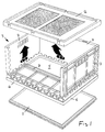
- Figur 1:
- Eine perspektivische Darstellung des Behälters mit abgesenktem Boden und angehobenem Deckel.
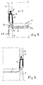
- Figur 2:
- Einen Ausschnitt aus einem senkrechten Schnitt durch zwei aufeinanderstehende, aufgeklappte Behälter, wobei der obere Behälter mit seinem Boden auf dem Deckel des unteren Behälters formschlüssig aufsitzt.
- Figur 3:
- Einen Ausschnitt aus einem senkrechten Schnitt durch zwei aufeinanderstehende Behälter, wobei der untere Behälter keinen Deckel aufweist, so daß der Boden des oberen Behälters in der oberen Öffnung des unteren Behälters formschlüssig einsitzt.
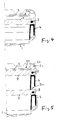
- figur 4:
- Einen Bereich eines senkrechten Schnitts durch einen zusammengeklappten Behälter mit Boden und Deckel.
- Figur 5:
- Einen senkrechten Schnitt durch einen zusammengeklappten Behälter, der zwei Rahmen aufweist.
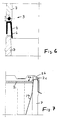
- Figur 6:
- Einen senkrechten Teilschnitt im Bereich zweier aufeinanderstehender, ausgeklappter Klapprahmen.
- Figur 7:
- Einen Schnitt im oberen Bereich eines aufgeklappten Behälters, bei dem der Deckel ein Inlay hält, das zwischen Deckel und Seitenwand festgeklemmt ist.
- Figur 8:
- Einen senkrechten Schnitt durch einen Behälter, der statt des Klapprahmens einen feststehenden Zwischenrahmen aufweist, der an der Ober- und Unterseite durch je einen Boden verschlossen ist.
- Figur 9:
- Einen Schnitt
ähnlich Figur 8, wobei die Oberseite durch einen Deckel verschlossen ist. - Figur 10:
- Einen Ausschnitt aus einem senkrechten Schnitt durch einen Behälter im Bodenbereich mit einem Schiebeelement zur Verriegelung.
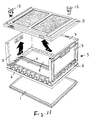
- Figur 11:
- Eine perspektivische Darstellung
ähnlich Figur 1 mit Steckelementen zur Verriegelung des Deckels an den aufgeklappten Wänden oder anderen Teilen. - Figur 12:
- Eine Seitenansicht des Behälters im Ausschnitt, mit Rippen an der Deckelunterseite.
- Figure 1:
- A perspective view of the container with the bottom lowered and the lid raised.
- Figure 2:
- A section of a vertical section through two superimposed, opened containers, the upper container with its bottom sitting positively on the lid of the lower container.
- Figure 3:
- A section of a vertical section through two containers standing one on top of the other, the lower container not having a lid, so that the bottom of the upper container sits positively in the upper opening of the lower container.
- figure 4:
- A section of a vertical section through a collapsed container with a base and lid.
- Figure 5:
- A vertical section through a collapsed container that has two frames.
- Figure 6:
- A vertical partial cut in the area of two folding frames that are folded out.
- Figure 7:
- A cut in the upper area of an opened container, in which the lid holds an inlay that is clamped between the lid and the side wall.
- Figure 8:
- A vertical section through a container, which instead of the snap frame has a fixed intermediate frame, which is closed on the top and bottom by a bottom.
- Figure 9:
- A section similar to Figure 8, wherein the top is closed by a lid.
- Figure 10:
- A section of a vertical section through a container in the bottom area with a sliding element for locking.
- Figure 11:
- A perspective view similar to Figure 1 with plug elements for locking the lid on the opened walls or other parts.
- Figure 12:
- A side view of the container in the cutout, with ribs on the underside of the lid.
Der Behälter weist einen Boden 1, einen Deckel 2 und einen oder mehrere dazwischen gesetzte Klapprahmen 3 auf. Der Deckel 2 kann auch durch einen Boden 1 und der Boden 1 durch einen Deckel 2 ersetzt werden.The container has a
Der Klapprahmen 3 weist einen waagerechten, nicht klappbaren Grundrahmen 4 auf, der eine rechteckförmige waagerechte Öffnung 5 umschließt. Der Grundrahmen weist vorzugsweise ein rechteckförmiges Profil 6 auf, das im Ausführungsbeispiel, siehe Figur 2 bis 7, einen Querschnitt in Form eines auf dem Kopf stehenden U's besitzt. Das Profil 6 bildet somit die vier Seiten des Grundrahmens 4 und sowohl auf den beiden Längsseiten als auch auf den beiden Querseiten ist auf der Oberseite jeden Profils eine Seitenwand 7 angelenkt, wobei die jeweilige Anlenkachse waagerecht und parallel zum Profil 6 verläuft. Durch diese Anlenkstellen 8 sind die vier Seitenwände 7 aus der senkrechten Stellung in die waagerechte Stellung nach innen klappbar, so daß im zusammengeklappten Zustand der Grundrahmen und die vier Seitenwände eine rechteckförmige Schicht geringer Höhe bilden. Auf diese Schicht kann dann auf die Unter- und Oberseite jeweils ein Boden, bzw. ein Deckel gesetzt werden, so daß im zusammengeklappten Zustand alle Teile eine feste, stabile Einheit bilden.The
Bei allen Teilen ist dafür gesorgt, daß sie zueinander passende Vorsprünge/Stufen und Rücksprünge/entgegengesetzte Stufen/Ausnehmungen aufweisen, die formschlüssig ineinanderpassen, so daß alle Teile aneinander Halt finden, sowohl im aufgeklappten als auch im zusammengeklappten Zustand, wie in den Figuren 2 bis 7 gezeigt ist:
An der Unterseite des nach unten offenen Profils 6 ist der Boden 1 mit seinen Rändern formschlüssig gehalten, wobei der wannenförmige Boden 1 mit seinen senkrechten Seitenwänden das Profil 6 außen umgreift, siehe Figur 2 bis 5. Die Unterseite des Bodens 1 bildet einen wannenförmigen Vorsprungsbereich 1a, der nach unten vorsteht und in einer wannenförmigen Ausnehmung 2a entsprechend der Form des Deckels 2 zur Einlage gelangt, siehe Figur 2. Alternativ kann aber auch der Boden 1 in der oberen Öffnung eines darunterliegenden ausgeklappten Behälters zwischen den oberen Kanten der Seitenwände 7 formschlüssig einliegen, siehe Figur 3.All parts are ensured that they have mutually matching projections / steps and recesses / opposite steps / recesses which fit into one another in a form-fitting manner, so that all parts are held together, both in the opened and in the folded state, as in FIGS. 2 to 7 is shown:
On the underside of the
Der Deckel 2 weist an seiner Oberseite einen außen rundum umlaufenden Wulst 2b auf, der als rechteckförmiger Rand den Bereich 1a des Bodens 1 umfaßt. Dieser Wulst 2b bildet an seiner Unterseite eine außen umlaufende Nut 2c, die die oberen Ränder der Deckel 2 formschlüssig umgreift. Hierbei ist die Außenwand der Nut 2c weiter nach unten geführt und bildet einen senkrechten umlaufenden Seitenwandbereich 2d, der die Außenseite der senkrechten Seitenwand 7 außen umfaßt. Dieser Bereich 2d umfaßt darüberhinaus die Seitenwände auch im eingeklappten Zustand, siehe Figur 4 und 5. Ferner kann über den oberen Rand der senkrecht stehenden Wände 7 ein Inlay (Figur 7) gelegt werden, das von der Nut 2c des Deckels 2 übergriffen und festgehalten wird.The
Im zusammengelegtem bzw. eingeklapptem Zustand der Wände 7 bildet die Außenseite bzw. Oberseite der Seitenwand 7 mindestens einen nach oben stehenden Wulst 3a, nahe des Gelenks 8. Dieser Wulst 3a gibt auf seiner Innenseite dem Profil 6 eines darüberliegenden Klapprahmens 3 Halt, siehe Figur 5. Ferner gibt der Wulst 3a auch einen zusätzlichen Halt einem Deckel, da er in die Nut 2c formschlüssig eingreift.In the collapsed or folded state of the
Die Teile werden sicher aneinandergehalten, wenn außen Befestigungsbänder herumgelegt werden. Zusätzlich oder alternativ ist aber auch folgendes möglich:
In dem Bereich, in dem ein Boden an einem Klapprahmen, ein Deckel an einem Klapprahmen oder ein Klapprahmen an einem zweiten Klapprahmen anliegt, kann eines der beiden Teile ein Verriegelungsteil in Form eines Schiebeelementes 10 aufweisen, das innen gleitend und von Hand verschieblich gelagert ist und mindestens ein vorstehendes Hakenteil 10a aufweist, das ein Teil 11 hintergreift oder übergreift, das am benachbarten Behälterteil angeformt ist. Hierbei kann das Teil 11 durch Öffnungen soweit in das andere Teil hineingreifen, daß das Hakenteil 10a unsichtbar bleiben kann. Alternativ oder zusätzlich können aber auch Einsteckteile 12 vorgesehen sein, die durch Öffnungen eines Teils geführt werden und in einer damit fluchtenden Öffnung des benachbarten anliegenden Teils einrastend eingreifen.The parts are held securely together when fastening straps are laid around the outside. Additionally or alternatively, the following is also possible:
In the area in which a floor rests on a snap frame, a cover on a snap frame or a snap frame on a second snap frame, one of the two parts can have a locking part in the form of a sliding
Eine weitere Alternative ist in den Figuren 8 und 9 dargestellt. Hier sind die Außenwände nicht wie bei den vorherigen Ausführungen von einem klappbaren Rahmen gebildet, sondern von einem feststehendem Rahmen 13, der doppelwandig ausgebildet ist in Form eines umlaufenden Profils mit einem H-förmigen Querschnitt, wobei dieses Profil die Verdoppelung des Profils des Grundrahmens 4 ist. Es sind also zwei U-förmige Profilbereiche übereinander gesetzt, wobei der untere Profilbereich sich nach unten und der obere Profilbereich sich nach oben öffnet. Dieser Rahmen 13 kann auf der Oberseite in gleicher Weise durch eine Deckel 2 oder durch einen Boden 1 und an der Unterseite durch einen Deckel 2 oder einen Boden 1 verschlossen werden.Another alternative is shown in FIGS. 8 and 9. Here the outer walls are not like those previous embodiments formed by a foldable frame, but by a fixed
Die Seitenwände 7 weisen außen Versteifungsrippen 15 auf oder sind doppelwandig ausgeführt, so daß die Innen- und Außenseite im wesentlichen frei von Vorsprüngen sind.The
Werden große Behäler auf zwei, drei oder vier kleine Behälter gestellt, deren Gesamtfläche der des großen Behälters entspricht (Modulbauweise), so wird vorgeschlagen, daß die Unterseite des Deckels 2 paarweise Vorsprünge, insbesondere Stege 16 aufweist, zwischen denen die oberen Ränder von Seitenwänden 7 darunterliegender Behälter formschlüssig einliegen.If large containers are placed on two, three or four small containers, the total area of which corresponds to that of the large container (modular design), it is proposed that the underside of the
Claims (17)
Applications Claiming Priority (2)
| Application Number | Priority Date | Filing Date | Title |
|---|---|---|---|
| DE19924242679 DE4242679A1 (en) | 1992-12-17 | 1992-12-17 | Collapsible transport container as reusable packaging |
| DE4242679 | 1992-12-17 |
Publications (2)
| Publication Number | Publication Date |
|---|---|
| EP0602575A2 true EP0602575A2 (en) | 1994-06-22 |
| EP0602575A3 EP0602575A3 (en) | 1996-12-11 |
Family
ID=6475581
Family Applications (1)
| Application Number | Title | Priority Date | Filing Date |
|---|---|---|---|
| EP19930120048 Withdrawn EP0602575A3 (en) | 1992-12-17 | 1993-12-13 | Foldable container as multi-way package. |
Country Status (5)
| Country | Link |
|---|---|
| EP (1) | EP0602575A3 (en) |
| CZ (1) | CZ288121B6 (en) |
| DE (1) | DE4242679A1 (en) |
| HU (1) | HU212758B (en) |
| PL (1) | PL172474B1 (en) |
Cited By (7)
| Publication number | Priority date | Publication date | Assignee | Title |
|---|---|---|---|---|
| EP0759400A3 (en) * | 1995-07-26 | 1997-05-02 | Mckechnie Uk Ltd | Foldable container |
| EP0928745A3 (en) * | 1995-07-26 | 1999-08-18 | McKechnie U.K. Limited | Stackable collapsible container |
| US6708836B2 (en) | 1998-11-18 | 2004-03-23 | Steiner Technology Gmbh | Container consisting of a plurality of plates |
| US6863180B2 (en) | 2002-02-15 | 2005-03-08 | Rehrig Pacific Company | Collapsible container |
| US7104414B2 (en) | 2002-01-12 | 2006-09-12 | Rehrig Pacific Company | Collapsible container |
| US8726618B1 (en) * | 2013-03-21 | 2014-05-20 | Joseph N. Laurita | Method of making and using a foldable and stackable box |
| CN117068604A (en) * | 2023-08-25 | 2023-11-17 | 太仓欧克仓储设备有限公司 | A folding turnover box |
Families Citing this family (7)
| Publication number | Priority date | Publication date | Assignee | Title |
|---|---|---|---|---|
| DE9408039U1 (en) * | 1994-05-14 | 1994-07-14 | Rehau Ag + Co, 95111 Rehau | Foldable packaging container |
| DE19548113C2 (en) * | 1995-02-17 | 2003-04-10 | Schoeller Plast Transportbehae | container system |
| DE29516844U1 (en) * | 1995-10-25 | 1995-12-21 | De Ster N.V., Hoogstraten | Stackable container with lid for food, especially for food |
| DE19920605A1 (en) * | 1999-05-05 | 2000-11-16 | Ludwig Gebhardt Gmbh & Co Betr | Plastic transport and storage crate combines strength with space-saving folding characteristics |
| CN102582911A (en) * | 2011-01-14 | 2012-07-18 | 苏州工业园区新欣电子科技有限公司 | Fully-foldable plastic box |
| CH707201A2 (en) * | 2012-11-01 | 2014-05-15 | Utz Georg Holding Ag | Fixing element for positioning cuboid container in a vertical stack. |
| PL247126B1 (en) * | 2023-04-13 | 2025-05-19 | Siec Badawcza Lukasiewicz Poznanski Instytut Tech | Transport packaging |
Family Cites Families (6)
| Publication number | Priority date | Publication date | Assignee | Title |
|---|---|---|---|---|
| GB766409A (en) * | 1954-01-29 | 1957-01-23 | Zagerij En Kistenfabriek F L H | Foldable and dismountable packing container or case |
| GB1292439A (en) * | 1970-07-29 | 1972-10-11 | Jack Williams | Improvements relating to collapsible containers for the transport of goods |
| AU4147578A (en) * | 1978-03-08 | 1979-09-13 | Lees H J Holdings Pty Ltd | Collapsible container |
| SE500433C2 (en) * | 1990-05-25 | 1994-06-27 | Nefab Ab | Container |
| DE9116664U1 (en) * | 1990-11-27 | 1993-06-09 | Schoeller-Plast S.A., Romont | Reusable packaging |
| WO1992015490A1 (en) * | 1991-03-05 | 1992-09-17 | John Green | Foldable box |
-
1992
- 1992-12-17 DE DE19924242679 patent/DE4242679A1/en not_active Withdrawn
-
1993
- 1993-12-13 EP EP19930120048 patent/EP0602575A3/en not_active Withdrawn
- 1993-12-15 CZ CZ19932757A patent/CZ288121B6/en not_active IP Right Cessation
- 1993-12-17 PL PL93301538A patent/PL172474B1/en unknown
- 1993-12-17 HU HU9303657A patent/HU212758B/en not_active IP Right Cessation
Cited By (10)
| Publication number | Priority date | Publication date | Assignee | Title |
|---|---|---|---|---|
| EP0759400A3 (en) * | 1995-07-26 | 1997-05-02 | Mckechnie Uk Ltd | Foldable container |
| US5797508A (en) * | 1995-07-26 | 1998-08-25 | Mckechnie Uk Limited | Collapsible container |
| EP0928745A3 (en) * | 1995-07-26 | 1999-08-18 | McKechnie U.K. Limited | Stackable collapsible container |
| US6708836B2 (en) | 1998-11-18 | 2004-03-23 | Steiner Technology Gmbh | Container consisting of a plurality of plates |
| AT411991B (en) * | 1998-11-18 | 2004-08-26 | Steco Logistic Gmbh | CONTAINER MULTIPLE PANELS |
| US7104414B2 (en) | 2002-01-12 | 2006-09-12 | Rehrig Pacific Company | Collapsible container |
| US6863180B2 (en) | 2002-02-15 | 2005-03-08 | Rehrig Pacific Company | Collapsible container |
| US8726618B1 (en) * | 2013-03-21 | 2014-05-20 | Joseph N. Laurita | Method of making and using a foldable and stackable box |
| US8794441B1 (en) | 2013-03-21 | 2014-08-05 | Joseph N. Laurita | Apparatus for foldable and stackable box |
| CN117068604A (en) * | 2023-08-25 | 2023-11-17 | 太仓欧克仓储设备有限公司 | A folding turnover box |
Also Published As
| Publication number | Publication date |
|---|---|
| CZ288121B6 (en) | 2001-04-11 |
| HU9303657D0 (en) | 1994-04-28 |
| PL301538A1 (en) | 1994-06-27 |
| EP0602575A3 (en) | 1996-12-11 |
| CZ275793A3 (en) | 1994-07-13 |
| DE4242679A1 (en) | 1994-06-23 |
| HU212758B (en) | 1996-11-28 |
| PL172474B1 (en) | 1997-09-30 |
| HUT65899A (en) | 1994-07-28 |
Similar Documents
| Publication | Publication Date | Title |
|---|---|---|
| DE69308661T2 (en) | Stackable-nestable packaging box with skeleton-type sides | |
| EP0602575A2 (en) | Foldable container as multi-way package | |
| DE9203114U1 (en) | Folding box | |
| DE3521894A1 (en) | Stackable container | |
| EP0054884A1 (en) | Foldable display package | |
| DE2643720A1 (en) | TRANSPORT CONTAINER | |
| CH512365A (en) | Collapsible transport box | |
| DE68904791T2 (en) | FRAMEWORK STRUCTURE. | |
| EP0705764B1 (en) | Container in the form of a crate | |
| EP0835816A2 (en) | Container in the form of a crate | |
| EP0075655A1 (en) | Collapsible plastic case | |
| DE4432030C2 (en) | Straight-walled container that can be stacked inside and on top of one another with a lid | |
| DE2165676A1 (en) | CLOSED, STACKABLE TRANSPORT CONTAINER | |
| DE4322479C2 (en) | Transport box made of plastic | |
| DE19601689A1 (en) | Plastic container with base part and side walls | |
| EP0091718B1 (en) | Collapsible transport box | |
| DE8809938U1 (en) | Folding box for small parts | |
| DE2200945A1 (en) | Stackable and nestable container | |
| DE19602651A1 (en) | Plastic transport and storage container | |
| DE9405765U1 (en) | Flat stackable container | |
| DE2557751C3 (en) | Articulated connection, especially on a transport pallet | |
| DE8007232U1 (en) | Polygonal saddle box | |
| EP0563420B1 (en) | Collapsible storage and transport crate | |
| DE2826652C2 (en) | Load-bearing crates | |
| EP0939732B1 (en) | Container |
Legal Events
| Date | Code | Title | Description |
|---|---|---|---|
| PUAI | Public reference made under article 153(3) epc to a published international application that has entered the european phase |
Free format text: ORIGINAL CODE: 0009012 |
|
| AK | Designated contracting states |
Kind code of ref document: A2 Designated state(s): AT BE CH DE DK ES FR GB GR IE IT LI LU MC NL PT SE |
|
| PUAL | Search report despatched |
Free format text: ORIGINAL CODE: 0009013 |
|
| AK | Designated contracting states |
Kind code of ref document: A3 Designated state(s): AT BE CH DE DK ES FR GB GR IE IT LI LU MC NL PT SE |
|
| 17P | Request for examination filed |
Effective date: 19970522 |
|
| 17Q | First examination report despatched |
Effective date: 19970905 |
|
| RAP1 | Party data changed (applicant data changed or rights of an application transferred) |
Owner name: PERSTORP PLASTIC SYSTEMS AB |
|
| GRAG | Despatch of communication of intention to grant |
Free format text: ORIGINAL CODE: EPIDOS AGRA |
|
| GRAG | Despatch of communication of intention to grant |
Free format text: ORIGINAL CODE: EPIDOS AGRA |
|
| GRAH | Despatch of communication of intention to grant a patent |
Free format text: ORIGINAL CODE: EPIDOS IGRA |
|
| STAA | Information on the status of an ep patent application or granted ep patent |
Free format text: STATUS: THE APPLICATION IS DEEMED TO BE WITHDRAWN |
|
| 18D | Application deemed to be withdrawn |
Effective date: 19990316 |