EP0602599B1 - Rückstrahlfolie mit gekapselten Linsen auf einer Trägerschicht - Google Patents
Rückstrahlfolie mit gekapselten Linsen auf einer Trägerschicht Download PDFInfo
- Publication number
- EP0602599B1 EP0602599B1 EP19930120139 EP93120139A EP0602599B1 EP 0602599 B1 EP0602599 B1 EP 0602599B1 EP 19930120139 EP19930120139 EP 19930120139 EP 93120139 A EP93120139 A EP 93120139A EP 0602599 B1 EP0602599 B1 EP 0602599B1
- Authority
- EP
- European Patent Office
- Prior art keywords
- layer
- binder material
- fabric
- sheet
- retroreflective sheeting
- Prior art date
- Legal status (The legal status is an assumption and is not a legal conclusion. Google has not performed a legal analysis and makes no representation as to the accuracy of the status listed.)
- Expired - Lifetime
Links
Images
Classifications
-
- G—PHYSICS
- G02—OPTICS
- G02B—OPTICAL ELEMENTS, SYSTEMS OR APPARATUS
- G02B5/00—Optical elements other than lenses
- G02B5/12—Reflex reflectors
- G02B5/126—Reflex reflectors including curved refracting surface
- G02B5/128—Reflex reflectors including curved refracting surface transparent spheres being embedded in matrix
-
- Y—GENERAL TAGGING OF NEW TECHNOLOGICAL DEVELOPMENTS; GENERAL TAGGING OF CROSS-SECTIONAL TECHNOLOGIES SPANNING OVER SEVERAL SECTIONS OF THE IPC; TECHNICAL SUBJECTS COVERED BY FORMER USPC CROSS-REFERENCE ART COLLECTIONS [XRACs] AND DIGESTS
- Y10—TECHNICAL SUBJECTS COVERED BY FORMER USPC
- Y10T—TECHNICAL SUBJECTS COVERED BY FORMER US CLASSIFICATION
- Y10T428/00—Stock material or miscellaneous articles
- Y10T428/23—Sheet including cover or casing
- Y10T428/234—Sheet including cover or casing including elements cooperating to form cells
-
- Y—GENERAL TAGGING OF NEW TECHNOLOGICAL DEVELOPMENTS; GENERAL TAGGING OF CROSS-SECTIONAL TECHNOLOGIES SPANNING OVER SEVERAL SECTIONS OF THE IPC; TECHNICAL SUBJECTS COVERED BY FORMER USPC CROSS-REFERENCE ART COLLECTIONS [XRACs] AND DIGESTS
- Y10—TECHNICAL SUBJECTS COVERED BY FORMER USPC
- Y10T—TECHNICAL SUBJECTS COVERED BY FORMER US CLASSIFICATION
- Y10T428/00—Stock material or miscellaneous articles
- Y10T428/25—Web or sheet containing structurally defined element or component and including a second component containing structurally defined particles
- Y10T428/252—Glass or ceramic [i.e., fired or glazed clay, cement, etc.] [porcelain, quartz, etc.]
-
- Y—GENERAL TAGGING OF NEW TECHNOLOGICAL DEVELOPMENTS; GENERAL TAGGING OF CROSS-SECTIONAL TECHNOLOGIES SPANNING OVER SEVERAL SECTIONS OF THE IPC; TECHNICAL SUBJECTS COVERED BY FORMER USPC CROSS-REFERENCE ART COLLECTIONS [XRACs] AND DIGESTS
- Y10—TECHNICAL SUBJECTS COVERED BY FORMER USPC
- Y10T—TECHNICAL SUBJECTS COVERED BY FORMER US CLASSIFICATION
- Y10T428/00—Stock material or miscellaneous articles
- Y10T428/25—Web or sheet containing structurally defined element or component and including a second component containing structurally defined particles
- Y10T428/254—Polymeric or resinous material
-
- Y—GENERAL TAGGING OF NEW TECHNOLOGICAL DEVELOPMENTS; GENERAL TAGGING OF CROSS-SECTIONAL TECHNOLOGIES SPANNING OVER SEVERAL SECTIONS OF THE IPC; TECHNICAL SUBJECTS COVERED BY FORMER USPC CROSS-REFERENCE ART COLLECTIONS [XRACs] AND DIGESTS
- Y10—TECHNICAL SUBJECTS COVERED BY FORMER USPC
- Y10T—TECHNICAL SUBJECTS COVERED BY FORMER US CLASSIFICATION
- Y10T428/00—Stock material or miscellaneous articles
- Y10T428/29—Coated or structually defined flake, particle, cell, strand, strand portion, rod, filament, macroscopic fiber or mass thereof
- Y10T428/2982—Particulate matter [e.g., sphere, flake, etc.]
- Y10T428/2991—Coated
- Y10T428/2993—Silicic or refractory material containing [e.g., tungsten oxide, glass, cement, etc.]
- Y10T428/2996—Glass particles or spheres
-
- Y—GENERAL TAGGING OF NEW TECHNOLOGICAL DEVELOPMENTS; GENERAL TAGGING OF CROSS-SECTIONAL TECHNOLOGIES SPANNING OVER SEVERAL SECTIONS OF THE IPC; TECHNICAL SUBJECTS COVERED BY FORMER USPC CROSS-REFERENCE ART COLLECTIONS [XRACs] AND DIGESTS
- Y10—TECHNICAL SUBJECTS COVERED BY FORMER USPC
- Y10T—TECHNICAL SUBJECTS COVERED BY FORMER US CLASSIFICATION
- Y10T428/00—Stock material or miscellaneous articles
- Y10T428/29—Coated or structually defined flake, particle, cell, strand, strand portion, rod, filament, macroscopic fiber or mass thereof
- Y10T428/2982—Particulate matter [e.g., sphere, flake, etc.]
- Y10T428/2991—Coated
- Y10T428/2998—Coated including synthetic resin or polymer
-
- Y—GENERAL TAGGING OF NEW TECHNOLOGICAL DEVELOPMENTS; GENERAL TAGGING OF CROSS-SECTIONAL TECHNOLOGIES SPANNING OVER SEVERAL SECTIONS OF THE IPC; TECHNICAL SUBJECTS COVERED BY FORMER USPC CROSS-REFERENCE ART COLLECTIONS [XRACs] AND DIGESTS
- Y10—TECHNICAL SUBJECTS COVERED BY FORMER USPC
- Y10T—TECHNICAL SUBJECTS COVERED BY FORMER US CLASSIFICATION
- Y10T428/00—Stock material or miscellaneous articles
- Y10T428/31504—Composite [nonstructural laminate]
- Y10T428/31551—Of polyamidoester [polyurethane, polyisocyanate, polycarbamate, etc.]
-
- Y—GENERAL TAGGING OF NEW TECHNOLOGICAL DEVELOPMENTS; GENERAL TAGGING OF CROSS-SECTIONAL TECHNOLOGIES SPANNING OVER SEVERAL SECTIONS OF THE IPC; TECHNICAL SUBJECTS COVERED BY FORMER USPC CROSS-REFERENCE ART COLLECTIONS [XRACs] AND DIGESTS
- Y10—TECHNICAL SUBJECTS COVERED BY FORMER USPC
- Y10T—TECHNICAL SUBJECTS COVERED BY FORMER US CLASSIFICATION
- Y10T428/00—Stock material or miscellaneous articles
- Y10T428/31504—Composite [nonstructural laminate]
- Y10T428/31551—Of polyamidoester [polyurethane, polyisocyanate, polycarbamate, etc.]
- Y10T428/31573—Next to addition polymer of ethylenically unsaturated monomer
Definitions
- the present invention is directed to encapsulated-lens sheeting (as originally described in US-A-3,190,178) and especially forms of such sheeting that incorporate a support sheet or fabric which allow the sheeting to be incorporated into a garment to be worn by pedestrians.
- Encapsulated-lens retroreflective sheeting offers bright retroreflection and maintains that reflection even when wet with water.
- Such sheeting has been provided in flexible fabric supported forms for application to garments to make pedestrians wearing the garments more visible at night to drivers of approaching vehicles. Because the sheeting incorporates a supporting fabric it can be easily sewn or adhered or otherwise incorporated into a garment.
- EP-A-291205 discloses an article and a method according to the preamble of the independent claims.
- the present invention provides a new supported encapsulated lens retroreflective sheeting that alleviates the noted problems, and the invention also provides a new process for preparing such sheeting.
- the new process comprises (1) preparing a layer of binder material having a layer of retroreflective elements disposed over and partially embedded in its top surface ("top” refers to the exterior surface of the sheeting through which light is received for reflection, or, with respect to the underlying components of the sheeting, the surface that faces in the same direction as the top exterior surface; "bottom” refers to the surface opposite from the top surface); (2) applying a support sheet to the bottom surface of the layer of binder material; (3) disposing a transparent cover sheet over the protruding surfaces of the layer of retroreflective elements; and (4) applying a network-like pattern of heat and pressure against the bottom surface of the support sheet so as to emboss the support sheet and further emboss binder material from the layer of binder material into contact with the cover sheet.
- the embossing step forms a unified article in which the layer of binder material and cover sheet are adhered together and a plurality of cells is formed within which retroreflective elements are hermetically sealed.
- the layer of binder material develops an embossed configuration and the support sheet follows that embossed configuration.
- the support sheet is applied to the bottom surface of the layer of binder material prior to the application of embossing heat and pressure.
- the support sheet comprises a fabric, and the binder material from the layer of binder material penetrates into interstices of the fabric during the lamination step.
- a new sheeting which in brief summary comprises (1) a layer of binder material having a layer of retroreflective elements disposed over and partially embedded in its top surface; (2) a transparent cover sheet disposed in spaced relation from the layer of retroreflective elements; (3) a network of narrow intersecting bonds comprising binder material embossed from the layer of binder material into contact with the cover sheet so as to adhere the layer of binder material and cover sheet together and form a plurality of cells within which retroreflective elements are hermetically sealed; and (4) a support sheet lastingly and directly adhered to the bottom surface of the layer of binder material and embossed with the layer of binder material so as to follow the embossed configuration of the bottom surface of the layer of binder material.
- the support sheet comprises a fabric, and binder material from the layer of binder material penetrates into interstices of the fabric to enhance the adhesion of the fabric to the layer of binder material.
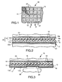
- Figure 1 is a top view of a portion of sheeting of the invention
- Figure 2 is a greatly enlarged cross-section of an intermediate assembly occurring during preparation of sheeting of the invention
- Figure 3 is a greatly enlarged cross-section of sheeting of the invention together with parts of apparatus used during manufacture of the sheeting.
- FIG. 1 An exemplary finished sheeting of the invention 10 is pictured in top view in Figure 1 of the drawings and in greatly enlarged cross-section in Figure 3 (along the lines 3-3 in Figure 1).
- the exemplary sheeting 10 comprises
- the microspheres 12 are typically first removably and partially embedded in a carrier sheet such as polyethylene-coated paper (see US-A-3,190,178).
- a carrier sheet such as polyethylene-coated paper (see US-A-3,190,178).
- the surfaces of the microspheres protruding from the carrier sheet are covered with the specularly reflective material 13 by vapor-deposition.
- a representative carrier sheet 18 is pictured in Figure 2 of the drawings and includes a paper sheet 18a and polyethylene layer 18b.
- the intermediate product of microspheres embedded in the carrier sheet and covered with specularly reflective material is labeled as 19 in Figure 2.
- Binder material is then applied over the specularly reflective material as by coating the binder material from solution or a melt or by pressing a preformed layer of the binder material against the microspheres (see US-A-5,064,272, column 5, line 61, through column 6, line 17; the latter refers to the preferred practice of pressing the layer of binder material against the microspheres only to an extent that the binder material does not contact the portion of the coated specularly reflective material deposited onto the carrier sheet between the microspheres; thus when the carrier sheet is later separated from the layer of binder material, the specularly reflective material between the microspheres stays with the carrier sheet and does not cover the surface of the binder material between the microspheres, thereby minimizing coloration of the product by metallic specularly reflective material).
- the layer 11 is formed with the microspheres partially embedded in the layer 11 and also partially embedded in the carrier sheet. The result is the construction labeled 20 in Figure 2.
- the support sheet 16 is then laminated to the free surface of the layer of binder material.
- a lamination could occur later, for example, after removal of the temporary carrier sheet 18; but the assembly is better supported when lamination is performed with the carrier sheet in place.
- Lamination preferably is achieved by pressing the support sheet 16 against the binder material 11 and heating the assembly as by passing the assembly under pressure between a pair of rollers, represented in Figure 2 by the parts marked 21 and 22, at least one of which is heated.
- the support sheet 16 is a fabric, and during the lamination operation portions of the binder material 11 penetrate into interstices of the fabric thereby firmly bonding the fabric to the binder material.
- a film 17 may be removably applied over the bottom surface of the support fabric.
- One useful film is a two-layer film which has a heat-softenable layer 17a such as polyethylene and a nonsoftening layer 17b such as polyethylene terephthalate, and which can be heat-laminated to the support fabric.
- the film 17 becomes bonded to the support fabric, and can either remain as part of the final product or be stripped away prior to inclusion of the fabric in a garment or other use of the product.
- the carrier sheet 18 is stripped away, uncovering microspheres protruding from the layer 11 of binder material.
- a cover film 14 is laid against the protruding surfaces of the microspheres and the resulting assembly is subjected to an embossing operation as represented in Figure 3.
- the whole assembly comprising cover film 14, layer of binder material 11, support sheet 16 and protective sheet 17, is inserted between a pair of heated platens or rollers 24 and 25.
- One platen or roller (25) is an embossing platen having a pattern of raised ridges 26. The ridges 26 on the embossing platen press against the bottom of the protective sheet 17 to deform the protective sheet, support sheet 16, and binder layer 11 into the configuration shown in Figure 3.
- the layer 11 of binder material is heated and pressed sufficiently so that it floods the microspheres in the area pressed and contacts the cover film 14 to develop a bond 15.
- the pattern of ridges on the embossing platen is such as to form the network of narrow bonds 15 illustrated in Figure 1.
- the bonds intersect so as to define cells 27 within which microspheres are hermetically sealed.
- a variety of patterns can be used; for example the square cells of Figure 1 can instead have a hexagonal pattern.
- cover films for inclusion in encapsulated-lens sheeting are well known.
- polyolefin films which have good flexibility even in low-temperature environments are especially desirable; examples are polyethylene, polypropylene and ethylene-acrylic acid copolymers.
- Ultraviolet absorbers are desirably included, especially in the polyolefin films to avoid deterioration of the film and underlying elements during outdoor weathering. Because the described polyolefin films are softer and may not exhibit a desired resistance to penetration by microspheres during the embossing operation represented in Figure 3 of the drawings, the cover sheet desirably has a layer or coating (not pictured) of a harder, higher softening material as described in U.S. Pat.
- Polyurethanes are especially useful as the harder material, e.g., layers formed from aqueous colloidal urethane dispersion; or acrylic emulsions can also be used.
- Suitable commercial materials are sold under the tradenames of Neo Rez (polyurethanes) or Neo Cryl (acrylics) by Polyvinyl Chemical Industries.
- such layers can enhance adhesion between the cover film and the binder material embossed into contact with the cover film.
- the layers can be colored, as by inclusion of a dye.
- Highly plasticized polyvinyl chloride films may also be used as the cover film.
- binder materials to be used in sheeting of the invention should have low glass transition temperatures (T g ), e.g., -20°C or lower, to maintain good low temperature performance.
- T g glass transition temperatures
- a thermoplastic polyurethane polymer is especially useful as the binder material 11 and provides good durability and flexibility, including flexibility at low temperatures.
- aromatic polyurethanes discolor in sunlight, addition of a hiding type pigment such as titanium dioxide avoids any discoloration of the product.
- a white coloration is typically desired to minimize the gray or metallic color caused by a metal coating on the microspheres.
- Ethylene-acrylic acid copolymers are another useful polymer in the binder material, though it is difficult to add a pigment to such a material. If an ethylene-acrylic acid polymeric cover film is used with an ethylene-acrylic acid polymeric binder material, there is no need for a polyurethane hard layer on the cover film to achieve a good bond to the cover film.
- the binder material can comprise a mixture of polymeric materials as well as other ingredients.
- a vinyl chloride/acetate copolymer is desirably mixed with a polyurethane polymer to provide flexibility.
- Heat-stabilizers and antioxidants can also be added to improve weatherability.
- Fluorescent dyes are also useful to provide brightly visible colors.
- Fabrics are especially useful as the support sheet because they are durable, with high tensile strength; the binder material can penetrate the fabric to achieve a good bond; and fabrics avoid the plasticizers often included in polymeric films for flexibility, which can weaken adhesion and cause other problems.
- Spun-bond polyester fabrics are especially useful; they often comprise a bicomponent fiber with a polyethylene terephthalate core and a polyethylene or polyester outer layer that softens at a lower temperature than the polyethylene terephthalate core. Woven cloths are also useful.
- Polymeric films offer an alternative to fabric for some purposes.
- removable liners such as the liner 17 are preferred in sheeting of the invention, they can be avoided, for example, by coating the bottom surface of the fabric (opposite surface from that bonded to the layer of binder material) with a suitable repellent material.
- a suitable repellent material should be chosen that maintain adhesion to the binder material.
- corona treatments are preferred with the described polyethylene-containing spun-bonded fabrics to enhance adhesion.
- a finished product of the invention is thin, light weight and flexible, which preferably extends to low temperatures such as -20°C.
- the complete product, without protective film 17 is 325 micrometers or less thick and is sufficiently flexible so that it can be readily wrapped around a 3 millimeter-diameter (0.125 inch) mandrel at room temperature, and preferably at -20°C.
- the support sheet follows the embossed configuration of the bottom surface of the layer of binder material and therefore there are no voids for collection of moisture.
- sheeting of the invention can be used by itself, e.g., as a sign that can be unwound from a storage roll and mounted where needed, as on the rear of a vehicle.
- a solution of binder material prepared from the ingredients listed below was coated over a sheet 19 comprising a carrier sheet 18 in which microspheres 12 averaging 65 micrometers in diameter were embedded to about 30% of their diameter and coated with vapor - deposited aluminum.
- Thermoplastic polyurethane resin 16.99 Vinyl chloride/acetate copolymer 6.73 Titanium dioxide 7.00 Antioxidant 0.48 Stearic acid 0.48 Methyl ethyl ketone 49.49 Cyclohexanone 17.88
- the coated solution was dried at an elevated temperature of 120°C (80-120°C is a useful range) to a thickness of about 50 micrometers.
- polyester textile fabric (Toray textile fabric No. 501) was laminated to the dried exposed surface of the layer of binder material; a temperature of 100°C and 5 kg f /cm 2 pressure was used (ranges of 70-100°C and 3-5 kg f /cm 2 are useful).
- a two-layer protective film 17 comprising a polyethylene top layer and polyethylene terephthalate bottom layer had been previously laminated to the bottom surface of the fabric.
- a nonwoven spun-bond fabric comprising bicomponent fibers having a polyethylene layer on a polyethylene terephthalate core (Unitika nonwoven fabric S1003WDO) was laminated to the layer of binder material instead of the polyester fabric.
- the lamination temperature and pressure were 100°C and 5 kg f /cm 2 , respectively.
- protective film 17 was not used.
- the carrier sheet 18 was then stripped away, and a 75 micrometer-thick cover film 14 of extruded ethylene/acrylic acid copolymer (Primacor 3440 supplied by Dow Chemical) containing an ultraviolet light absorber laid into contact with the exposed surfaces of the microspheres.
- This assembly was then subjected to embossing pressure using a smooth-surfaced rubber-covered top pressure roll heated to 160°C and a bottom metal roll heated to 80°C and carrying a network of embossing ridges that intersect in a hexagonal pattern.
- the rolls were pressed together to develop a pressure of 3-5 kg f /cm 2 and the assembly was pulled between the rolls at a rate of 3 meters per minute.
- the protective film 17 was removed after the embossing operation.
- a woven polyester fabric (a 100 percent polyester 85.5 X 60 construction weighing 3.1 ounces/yard 2 using textured polyester yarns, 1/150/34 warp and fill supplied by Milliken) was used as the support sheet.
- lamination of the fabric to the bottom layer of binder material and embossing of the assembly to the cover film were performed simultaneously.
- the top pressure roll was unheated and the bottom metal roll was heated to 215°C.
Landscapes
- Physics & Mathematics (AREA)
- General Physics & Mathematics (AREA)
- Optics & Photonics (AREA)
- Laminated Bodies (AREA)
- Optical Elements Other Than Lenses (AREA)
- Prostheses (AREA)
Claims (10)
- Retroreflektierende Folie mit Träger mit:
(a) einer Schicht aus Bindemittelmaterial (11) mit einer Schicht aus retroreflektierenden Elementen (12), die über ihrer Oberseite angeordnet und teilweise darin eingebettet sind; (b) einer transparenten Abdeckbahn (14), die in beabstandeter Beziehung von der Schicht aus retroreflektierenden Elementen und auf ihrer Oberseite angeordnet ist; (c) einem Netz aus schmalen, sich schneidenden Verbindungen (15), die Bindemittelmaterial aufweisen, das aus der Schicht aus Bindemittelmaterial durch Prägen in Berührung mit der Abdeckbahn gebracht ist, um die Schicht aus Bindemittelmaterial und die Abdeckbahn miteinander zu verkleben und mehrere Zellen zu bilden, in denen retroreflektierende Elemente hermetisch eingeschlossen sind; wobei das Prägen der Schicht aus Bindemittelmaterial die Unterseite der Schicht aus Bindemittelmaterial mit einer geprägten Konfiguration hinterläßt; und (d) einer Trägerbahn (16), die dauerhaft und direkt auf die Unterseite der Schicht aus Bindemittelmaterial geklebt und mit der Schicht aus Bindemittelmaterial geprägt ist, um der geprägten Konfiguration der Unterseite zu folgen,
dadurch gekennzeichnet, daß die Trägerbahn (16) ein Textilmaterial aufweist und daß Bindemittelmaterial aus der Schicht aus Bindemittelmaterial in Lücken des Textilmaterials eindringt. - Retroreflektierende Folie nach Anspruch 1, wobei die Abdeckbahn ein Polyolefin aufweist.
- Retroreflektierende Folie nach Anspruch 2, wobei das Polyolefin ein Ethylen-Acrylsäure-Polymer aufweist.
- Retroreflektierende Folie nach einem der Ansprüche 1 bis 3, wobei das Bindemittelmaterial ein Polyurethan aufweist.
- Retroreflektierende Folie nach einem der Ansprüche 1 bis 4, wobei die Abdeckbahn ein Polyolefin aufweist und die von dem Bindemittelmaterial berührte Oberfläche der Abdeckbahn mit einer Schicht auf Polyurethanbasis überzogen ist.
- Retroreflektierende Folie nach einem der Ansprüche 1 bis 5, wobei ein Schutzfilm (17) die Unterseite des Trägertextilmaterials (16) überzieht.
- Retroreflektierende Folie nach Anspruch 6, wobei der Schutzfilm (17) eine obere Schicht aus wärmeerweichbarem Material und eine untere Schicht aufweist und der Schutzfilm mittels der wärmeerweichbaren Schicht auf das Trägermaterial wärmelaminiert ist.
- Retroreflektierende Folie nach einem der Ansprüche 1 bis 7, wobei die Schicht aus Bindemittelmaterial etwa zwischen 25 und 50 Mikrometern dick ist.
- Verfahren zur Herstellung einer retroreflektierenden Folie mit Träger mit den folgenden Schritten: (a) Herstellen einer Schicht aus Bindemittelmaterial (11) mit einer Schicht aus retroreflektierenden Elementen (12), die über ihrer Oberseite angeordnet und teilweise darin eingebettet sind; (b) Anordnen einer transparenten Abdeckbahn (14) über den vorragenden Oberflächen der Schicht aus retroreflektierenden Elementen; und (c) Ausüben eines netzartigen Wärme- und Druckmusters auf die Unterseite einer Trägerbahn (16), um die Trägerbahn zu prägen und ferner Bindemittelmaterial aus der Schicht aus Bindemittelmaterial durch Prägen in Berührung mit der Abdeckbahn zu bringen, wobei (d) die Trägerbahn (16) auf die Unterseite der Schicht aus Bindemittelmaterial vor Ausüben des netzartigen Wärme- und Druckmusters aufgetragen wird, wobei ein Kombinationsartikel gebildet wird, in dem die Schicht aus Bindemittelmaterial und die Abdeckbahn miteinander verklebt und mehrere Zellen gebildet sind, in denen retroreflektierende Elemente hermetisch eingeschlossen sind, und die Trägerbahn dauerhaft an die Unterseite der Schicht aus Bindemittelmaterial geklebt ist und der geprägten Konfiguration der Schicht aus Bindemittelmaterial folgt, dadurch gekennzeichnet, daß die Trägerbahn (16) ein Textilmaterial aufweist und daß Bindemittelmaterial während des Laminierschritts aus der Schicht aus Bindemittelmaterial in Lücken des Textilmaterials eindringt.
- Verfahren nach Anspruch 9, wobei die Trägerbahn durch Wärme und Druck auf die Unterseite der Schicht aus Bindemittelmaterial vor Ausüben von Prägewärme und -druck laminiert wird.
Applications Claiming Priority (2)
| Application Number | Priority Date | Filing Date | Title |
|---|---|---|---|
| US07/991,097 US5378520A (en) | 1992-12-16 | 1992-12-16 | Supported encapsulated-lens retroreflective sheeting |
| US991097 | 1992-12-16 |
Publications (2)
| Publication Number | Publication Date |
|---|---|
| EP0602599A1 EP0602599A1 (de) | 1994-06-22 |
| EP0602599B1 true EP0602599B1 (de) | 1998-10-21 |
Family
ID=25536870
Family Applications (1)
| Application Number | Title | Priority Date | Filing Date |
|---|---|---|---|
| EP19930120139 Expired - Lifetime EP0602599B1 (de) | 1992-12-16 | 1993-12-14 | Rückstrahlfolie mit gekapselten Linsen auf einer Trägerschicht |
Country Status (8)
| Country | Link |
|---|---|
| US (1) | US5378520A (de) |
| EP (1) | EP0602599B1 (de) |
| JP (1) | JP3419857B2 (de) |
| CN (1) | CN1035345C (de) |
| AU (1) | AU667973B2 (de) |
| CA (1) | CA2102144A1 (de) |
| DE (1) | DE69321695T2 (de) |
| ES (1) | ES2123608T3 (de) |
Cited By (2)
| Publication number | Priority date | Publication date | Assignee | Title |
|---|---|---|---|---|
| US9085121B2 (en) | 1999-05-13 | 2015-07-21 | 3M Innovative Properties Company | Adhesive-backed articles |
| US9427935B2 (en) | 2008-11-18 | 2016-08-30 | Avery Dennison Corporation | Thermoformable three dimensional retroreflective article and method of manufacture |
Families Citing this family (30)
| Publication number | Priority date | Publication date | Assignee | Title |
|---|---|---|---|---|
| JP3040267B2 (ja) * | 1992-10-23 | 2000-05-15 | 日本カーバイド工業株式会社 | 再帰反射性シートの製造方法 |
| US5977263A (en) * | 1992-12-10 | 1999-11-02 | 3M Innovative Properties Company | Thermal transfer compositions, articles and graphic articles made with same |
| WO1996003285A1 (en) * | 1994-07-26 | 1996-02-08 | Minnesota Mining And Manufacturing Company | Retroreflective graphic articles and thermal transfer articles |
| US5514441A (en) * | 1994-09-30 | 1996-05-07 | Avery Dennison Corporation | Retroreflective sheeting with improved topcoat |
| JP2905102B2 (ja) * | 1994-10-21 | 1999-06-14 | 紀和化学工業株式会社 | 再帰性高輝度反射シートの製造方法 |
| WO1996017263A2 (en) * | 1994-11-29 | 1996-06-06 | Minnesota Mining And Manufacturing Company | Transparent decorative article having an etched appearing/prismatic image thereon |
| CA2222508A1 (en) * | 1995-06-22 | 1997-01-09 | Thanh-Huong T. Nguyen | Encapsulated-lens retroreflective sheeting |
| US5674605A (en) * | 1995-09-15 | 1997-10-07 | Minnesota Mining And Manufacturing Company | Retroreflective transfer sheet and applique |
| US5645938A (en) * | 1995-09-15 | 1997-07-08 | Minnesota Mining And Manufacturing Company | Retroreflective article containing a polyester polyurethane binder layer |
| US5976669A (en) * | 1996-12-20 | 1999-11-02 | 3M Innovative Properties Company | Retroreflective article having launderably durable bead-bond |
| US5965256A (en) * | 1997-10-14 | 1999-10-12 | Minnesota Mining And Manufacturing Company | Protective films and coatings |
| US6054208A (en) * | 1998-01-16 | 2000-04-25 | Avery Dennison Corporation | Film forming mixtures, image bearing films and image bearing retroreflective sheeting |
| DE69935740T2 (de) * | 1998-10-30 | 2007-12-27 | Avery Dennison Corp., Pasadena | Verfahren zur Herstellung einer retroreflektierenden Folie mit einem Bild zur Echtheitsprüfung |
| US6224792B1 (en) | 1999-04-13 | 2001-05-01 | 3M Innovative Properties Company | Cutting and edge sealing cellular retroreflective sheeting |
| US6376045B1 (en) | 1999-05-24 | 2002-04-23 | Tyco Adhesives Lp | Hand tearable patterned retroreflective material |
| US6586067B2 (en) | 2001-04-02 | 2003-07-01 | Avery Dennison Corporation | Encapsulated lens retroreflective sheeting |
| ITMO20010157A1 (it) * | 2001-07-27 | 2003-01-27 | Giorgio Corradi | Metodo per la fabbricazione di un laminato retroriflettente |
| US20030180541A1 (en) * | 2002-02-04 | 2003-09-25 | Naik Kirit N. | Topcoat compositions, substrates coated therewith and method of making and using the same |
| US20070218267A1 (en) * | 2006-03-17 | 2007-09-20 | Votel Thomas F | Reflective composition and garment |
| BR112012028904A2 (pt) | 2010-05-25 | 2016-07-26 | 3M Innovative Properties Co | artigo retrorrefletivo de lentes expostas |
| JP5766343B1 (ja) * | 2014-10-24 | 2015-08-19 | ユニチカスパークライト株式会社 | 再帰性反射性材料 |
| CN107529839A (zh) * | 2015-02-26 | 2018-01-02 | 朝山贵生 | 载有回复反射性的设计图案的时尚产品 |
| US10865136B2 (en) | 2016-07-22 | 2020-12-15 | Alliance For Sustainable Energy, Llc | Transparent and insulating materials having evacuated capsules |
| CN107942424B (zh) * | 2017-11-27 | 2020-07-07 | 复旦大学 | 一种可变色逆反射材料的制备方法 |
| MX2020013679A (es) * | 2018-07-13 | 2021-03-02 | Promax Ind Aps | Marcas viales y su metodo de fabricacion. |
| CN111959054B (zh) * | 2019-05-14 | 2022-05-13 | 黛玛诗时尚服装有限公司 | 阳光下变色面料 |
| CN110571297B (zh) * | 2019-09-26 | 2024-05-07 | 常州斯威克新材料科技有限公司 | 一种网格高黏性光伏反光贴膜及其制作方法 |
| US20210259349A1 (en) * | 2020-02-20 | 2021-08-26 | James Sanchez | Light Reflecting Headgear Assembly |
| CN116234467B (zh) * | 2020-09-24 | 2026-01-09 | 3M创新有限公司 | 包括回射层合物的离散岛状物的织物和服装 |
| WO2023203406A1 (en) * | 2022-04-19 | 2023-10-26 | 3M Innovative Properties Company | Retroreflective article |
Family Cites Families (18)
| Publication number | Priority date | Publication date | Assignee | Title |
|---|---|---|---|---|
| US3190178A (en) * | 1961-06-29 | 1965-06-22 | Minnesota Mining & Mfg | Reflex-reflecting sheeting |
| US3758192A (en) * | 1970-08-20 | 1973-09-11 | Minnesota Mining & Mfg | Reflex-reflective structures including fabric and transfer foils |
| US4025159A (en) * | 1976-02-17 | 1977-05-24 | Minnesota Mining And Manufacturing Company | Cellular retroreflective sheeting |
| JPH0617921B2 (ja) * | 1984-03-15 | 1994-03-09 | 西武ポリマ化成株式会社 | セル状反射シート |
| US4533592A (en) * | 1984-08-02 | 1985-08-06 | Minnesota Mining And Manufacturing Company | Thermally stable flame retardant reflective and retroreflective trim |
| AU581288B2 (en) * | 1985-03-01 | 1989-02-16 | Minnesota Mining And Manufacturing Company | Flat transparent top coat for retroreflective coating |
| US4637950A (en) * | 1985-05-01 | 1987-01-20 | Minnesota Mining And Manufacturing Company | Delamination-resistant cellular retroreflective sheeting |
| US5064272A (en) * | 1985-11-18 | 1991-11-12 | Minnesota Mining And Manufacturing Company | Encapsulated-lens retroreflective sheeting and method of making |
| US4897136A (en) * | 1985-11-18 | 1990-01-30 | Minnesota Mining And Manufacturing Company | Method of making encapsulated-lens retroreflective sheeting |
| US4663213A (en) * | 1985-11-18 | 1987-05-05 | Minnesota Mining And Manufacturing Company | Transparent multi-layer cover film for retroreflective sheeting |
| US4763985A (en) * | 1986-08-01 | 1988-08-16 | Minnesota Mining And Manufacturing Company | Retroreflective sheet with enhanced brightness |
| US4896943A (en) * | 1987-05-13 | 1990-01-30 | Minnesota Mining And Manufacturing Company | Encapsulated-lens retroreflective sheeting having improved cover film |
| US5066098A (en) * | 1987-05-15 | 1991-11-19 | Minnesota Mining And Manufacturing Company | Cellular encapsulated-lens high whiteness retroreflective sheeting with flexible cover sheet |
| AU614466B2 (en) * | 1989-05-23 | 1991-08-29 | Minnesota Mining And Manufacturing Company | Flexible, substrate-insular retroreflective sheeting |
| US5069964A (en) * | 1989-05-23 | 1991-12-03 | Minnesota Mining And Manufacturing Company | Flexible, substrate-insular retroreflective sheeting |
| US4957335A (en) * | 1989-05-26 | 1990-09-18 | Minnesota Mining And Manufacturing Company | Microsphere-based retroreflective articles with enhanced retroreflective brightness |
| US5110655A (en) * | 1990-10-17 | 1992-05-05 | Minnesota Mining And Manufacturing Company | Removable, high temperature resistant retroreflective marking material |
| US5238733A (en) * | 1991-09-30 | 1993-08-24 | Minnesota Mining And Manufacturing Company | Stretchable nonwoven webs based on multi-layer blown microfibers |
-
1992
- 1992-12-16 US US07/991,097 patent/US5378520A/en not_active Expired - Lifetime
-
1993
- 1993-11-01 CA CA 2102144 patent/CA2102144A1/en not_active Abandoned
- 1993-11-02 AU AU50418/93A patent/AU667973B2/en not_active Ceased
- 1993-12-07 CN CN93120141A patent/CN1035345C/zh not_active Expired - Fee Related
- 1993-12-14 DE DE69321695T patent/DE69321695T2/de not_active Expired - Fee Related
- 1993-12-14 JP JP31324193A patent/JP3419857B2/ja not_active Expired - Fee Related
- 1993-12-14 ES ES93120139T patent/ES2123608T3/es not_active Expired - Lifetime
- 1993-12-14 EP EP19930120139 patent/EP0602599B1/de not_active Expired - Lifetime
Cited By (3)
| Publication number | Priority date | Publication date | Assignee | Title |
|---|---|---|---|---|
| US9085121B2 (en) | 1999-05-13 | 2015-07-21 | 3M Innovative Properties Company | Adhesive-backed articles |
| US9427935B2 (en) | 2008-11-18 | 2016-08-30 | Avery Dennison Corporation | Thermoformable three dimensional retroreflective article and method of manufacture |
| US9821531B2 (en) | 2008-11-18 | 2017-11-21 | Avery Dennison Corporation | Thermoformable three dimensional retroreflective article and method of manufacture |
Also Published As
| Publication number | Publication date |
|---|---|
| US5378520A (en) | 1995-01-03 |
| AU667973B2 (en) | 1996-04-18 |
| DE69321695T2 (de) | 1999-04-08 |
| AU5041893A (en) | 1994-06-30 |
| JPH06214104A (ja) | 1994-08-05 |
| DE69321695D1 (de) | 1998-11-26 |
| CA2102144A1 (en) | 1994-06-17 |
| ES2123608T3 (es) | 1999-01-16 |
| CN1035345C (zh) | 1997-07-02 |
| EP0602599A1 (de) | 1994-06-22 |
| JP3419857B2 (ja) | 2003-06-23 |
| CN1090931A (zh) | 1994-08-17 |
Similar Documents
| Publication | Publication Date | Title |
|---|---|---|
| US5378520A (en) | Supported encapsulated-lens retroreflective sheeting | |
| KR100443626B1 (ko) | 지지체를가진미세구조제품및그제조방법 | |
| US4533592A (en) | Thermally stable flame retardant reflective and retroreflective trim | |
| US5207852A (en) | Method for making permeable retroreflective sheeting | |
| US6677028B1 (en) | Retroreflective articles having multilayer films and methods of manufacturing same | |
| CA2094899C (en) | Non-woven fluorescent retroreflective fabric | |
| EP0498581B1 (de) | Luftdurchlässiger und rückstrahlender Stoff und Verfahren zu dessen Herstellung | |
| US4505967A (en) | High-angularity retroreflective sheeting and method for manufacture | |
| US6376045B1 (en) | Hand tearable patterned retroreflective material | |
| US4648932A (en) | High-angularity retroreflective sheeting and method for manufacture | |
| JPS6338902A (ja) | 再帰反射性シ−ト | |
| EP1230084B1 (de) | Retroreflektierende gegenstände mit mehrlagigen folien und verfahren zu ihrer herstellung | |
| AU2431195A (en) | Retroreflective polymer coated flexible fabric material and method of manufacture | |
| CN116234467B (zh) | 包括回射层合物的离散岛状物的织物和服装 | |
| EP0815477B1 (de) | Retroreflektive auflage | |
| JPH05116256A (ja) | 継ぎ構造体及びその形成方法 | |
| EP0593826B1 (de) | Rückstrahlende Vorrichtung | |
| CA2214121C (en) | Retroreflective applique | |
| MXPA98003456A (en) | Microstructured articles with support and fabricac methods |
Legal Events
| Date | Code | Title | Description |
|---|---|---|---|
| PUAI | Public reference made under article 153(3) epc to a published international application that has entered the european phase |
Free format text: ORIGINAL CODE: 0009012 |
|
| AK | Designated contracting states |
Kind code of ref document: A1 Designated state(s): DE ES FR GB IT NL SE |
|
| 17P | Request for examination filed |
Effective date: 19941208 |
|
| 17Q | First examination report despatched |
Effective date: 19970211 |
|
| GRAG | Despatch of communication of intention to grant |
Free format text: ORIGINAL CODE: EPIDOS AGRA |
|
| GRAG | Despatch of communication of intention to grant |
Free format text: ORIGINAL CODE: EPIDOS AGRA |
|
| GRAH | Despatch of communication of intention to grant a patent |
Free format text: ORIGINAL CODE: EPIDOS IGRA |
|
| GRAH | Despatch of communication of intention to grant a patent |
Free format text: ORIGINAL CODE: EPIDOS IGRA |
|
| GRAH | Despatch of communication of intention to grant a patent |
Free format text: ORIGINAL CODE: EPIDOS IGRA |
|
| GRAH | Despatch of communication of intention to grant a patent |
Free format text: ORIGINAL CODE: EPIDOS IGRA |
|
| GRAA | (expected) grant |
Free format text: ORIGINAL CODE: 0009210 |
|
| RIN1 | Information on inventor provided before grant (corrected) |
Inventor name: LIGHTLE, VERA L., C/O MINNESOTA MINING AND Inventor name: NAGAOKA, YOSHIYUKI, C/O MINNESOTA MINING AND |
|
| AK | Designated contracting states |
Kind code of ref document: B1 Designated state(s): DE ES FR GB IT NL SE |
|
| PGFP | Annual fee paid to national office [announced via postgrant information from national office to epo] |
Ref country code: SE Payment date: 19981119 Year of fee payment: 6 |
|
| PGFP | Annual fee paid to national office [announced via postgrant information from national office to epo] |
Ref country code: NL Payment date: 19981126 Year of fee payment: 6 |
|
| REF | Corresponds to: |
Ref document number: 69321695 Country of ref document: DE Date of ref document: 19981126 |
|
| PGFP | Annual fee paid to national office [announced via postgrant information from national office to epo] |
Ref country code: ES Payment date: 19981217 Year of fee payment: 6 |
|
| ET | Fr: translation filed | ||
| REG | Reference to a national code |
Ref country code: ES Ref legal event code: FG2A Ref document number: 2123608 Country of ref document: ES Kind code of ref document: T3 |
|
| PLBE | No opposition filed within time limit |
Free format text: ORIGINAL CODE: 0009261 |
|
| STAA | Information on the status of an ep patent application or granted ep patent |
Free format text: STATUS: NO OPPOSITION FILED WITHIN TIME LIMIT |
|
| 26N | No opposition filed | ||
| PG25 | Lapsed in a contracting state [announced via postgrant information from national office to epo] |
Ref country code: SE Free format text: LAPSE BECAUSE OF NON-PAYMENT OF DUE FEES Effective date: 19991215 |
|
| PG25 | Lapsed in a contracting state [announced via postgrant information from national office to epo] |
Ref country code: NL Free format text: LAPSE BECAUSE OF NON-PAYMENT OF DUE FEES Effective date: 20000701 |
|
| EUG | Se: european patent has lapsed |
Ref document number: 93120139.6 |
|
| NLV4 | Nl: lapsed or anulled due to non-payment of the annual fee |
Effective date: 20000701 |
|
| PG25 | Lapsed in a contracting state [announced via postgrant information from national office to epo] |
Ref country code: ES Free format text: LAPSE BECAUSE OF NON-PAYMENT OF DUE FEES Effective date: 20001215 |
|
| PGFP | Annual fee paid to national office [announced via postgrant information from national office to epo] |
Ref country code: FR Payment date: 20011120 Year of fee payment: 9 |
|
| PGFP | Annual fee paid to national office [announced via postgrant information from national office to epo] |
Ref country code: GB Payment date: 20011122 Year of fee payment: 9 |
|
| REG | Reference to a national code |
Ref country code: GB Ref legal event code: IF02 |
|
| PG25 | Lapsed in a contracting state [announced via postgrant information from national office to epo] |
Ref country code: GB Free format text: LAPSE BECAUSE OF NON-PAYMENT OF DUE FEES Effective date: 20021214 |
|
| GBPC | Gb: european patent ceased through non-payment of renewal fee |
Effective date: 20021214 |
|
| PG25 | Lapsed in a contracting state [announced via postgrant information from national office to epo] |
Ref country code: FR Free format text: LAPSE BECAUSE OF NON-PAYMENT OF DUE FEES Effective date: 20030901 |
|
| REG | Reference to a national code |
Ref country code: FR Ref legal event code: ST |
|
| REG | Reference to a national code |
Ref country code: ES Ref legal event code: FD2A Effective date: 20010113 |
|
| PG25 | Lapsed in a contracting state [announced via postgrant information from national office to epo] |
Ref country code: IT Free format text: LAPSE BECAUSE OF NON-PAYMENT OF DUE FEES Effective date: 20051214 |
|
| PGFP | Annual fee paid to national office [announced via postgrant information from national office to epo] |
Ref country code: DE Payment date: 20060131 Year of fee payment: 13 |
|
| PG25 | Lapsed in a contracting state [announced via postgrant information from national office to epo] |
Ref country code: DE Free format text: LAPSE BECAUSE OF NON-PAYMENT OF DUE FEES Effective date: 20070703 |