EP0602611B1 - Brosse à dents - Google Patents
Brosse à dents Download PDFInfo
- Publication number
- EP0602611B1 EP0602611B1 EP93120157A EP93120157A EP0602611B1 EP 0602611 B1 EP0602611 B1 EP 0602611B1 EP 93120157 A EP93120157 A EP 93120157A EP 93120157 A EP93120157 A EP 93120157A EP 0602611 B1 EP0602611 B1 EP 0602611B1
- Authority
- EP
- European Patent Office
- Prior art keywords
- handle
- brushneck
- toothbrush according
- articulated
- fork
- Prior art date
- Legal status (The legal status is an assumption and is not a legal conclusion. Google has not performed a legal analysis and makes no representation as to the accuracy of the status listed.)
- Expired - Lifetime
Links
- 238000007789 sealing Methods 0.000 claims abstract description 49
- 230000008878 coupling Effects 0.000 claims abstract description 31
- 238000010168 coupling process Methods 0.000 claims abstract description 31
- 238000005859 coupling reaction Methods 0.000 claims abstract description 31
- 230000002441 reversible effect Effects 0.000 claims abstract description 4
- 239000013013 elastic material Substances 0.000 claims abstract description 3
- 230000006835 compression Effects 0.000 claims description 10
- 238000007906 compression Methods 0.000 claims description 10
- 238000007373 indentation Methods 0.000 claims description 6
- 239000011324 bead Substances 0.000 claims description 5
- 238000013016 damping Methods 0.000 claims description 4
- 230000001747 exhibiting effect Effects 0.000 claims description 3
- 230000002093 peripheral effect Effects 0.000 claims description 3
- 238000004140 cleaning Methods 0.000 description 6
- 230000001154 acute effect Effects 0.000 description 5
- 239000000463 material Substances 0.000 description 3
- 201000000251 Locked-in syndrome Diseases 0.000 description 1
- 230000015572 biosynthetic process Effects 0.000 description 1
- 238000005260 corrosion Methods 0.000 description 1
- 230000007797 corrosion Effects 0.000 description 1
- 238000011161 development Methods 0.000 description 1
- 230000018109 developmental process Effects 0.000 description 1
- 230000002349 favourable effect Effects 0.000 description 1
- 238000004519 manufacturing process Methods 0.000 description 1
- 239000002184 metal Substances 0.000 description 1
Images




Classifications
-
- A—HUMAN NECESSITIES
- A46—BRUSHWARE
- A46B—BRUSHES
- A46B5/00—Brush bodies; Handles integral with brushware
- A46B5/002—Brush bodies; Handles integral with brushware having articulations, joints or flexible portions
- A46B5/0054—Brush bodies; Handles integral with brushware having articulations, joints or flexible portions designed to allow relative positioning of the head to body
- A46B5/0062—Brush bodies; Handles integral with brushware having articulations, joints or flexible portions designed to allow relative positioning of the head to body being flexible or resilient during use
- A46B5/007—Inserts made of different material, e.g. springs, plates
-
- A—HUMAN NECESSITIES
- A46—BRUSHWARE
- A46B—BRUSHES
- A46B5/00—Brush bodies; Handles integral with brushware
- A46B5/002—Brush bodies; Handles integral with brushware having articulations, joints or flexible portions
- A46B5/0054—Brush bodies; Handles integral with brushware having articulations, joints or flexible portions designed to allow relative positioning of the head to body
- A46B5/0062—Brush bodies; Handles integral with brushware having articulations, joints or flexible portions designed to allow relative positioning of the head to body being flexible or resilient during use
-
- A—HUMAN NECESSITIES
- A46—BRUSHWARE
- A46B—BRUSHES
- A46B5/00—Brush bodies; Handles integral with brushware
- A46B5/06—Brush bodies; Handles integral with brushware in the form of tapes, chains, flexible shafts, springs, mats or the like
-
- A—HUMAN NECESSITIES
- A46—BRUSHWARE
- A46B—BRUSHES
- A46B7/00—Bristle carriers arranged in the brush body
- A46B7/04—Bristle carriers arranged in the brush body interchangeably removable bristle carriers
-
- A—HUMAN NECESSITIES
- A61—MEDICAL OR VETERINARY SCIENCE; HYGIENE
- A61C—DENTISTRY; APPARATUS OR METHODS FOR ORAL OR DENTAL HYGIENE
- A61C17/00—Devices for cleaning, polishing, rinsing or drying teeth, teeth cavities or prostheses; Saliva removers; Dental appliances for receiving spittle
-
- A—HUMAN NECESSITIES
- A46—BRUSHWARE
- A46B—BRUSHES
- A46B2200/00—Brushes characterized by their functions, uses or applications
- A46B2200/10—For human or animal care
- A46B2200/1066—Toothbrush for cleaning the teeth or dentures
-
- Y—GENERAL TAGGING OF NEW TECHNOLOGICAL DEVELOPMENTS; GENERAL TAGGING OF CROSS-SECTIONAL TECHNOLOGIES SPANNING OVER SEVERAL SECTIONS OF THE IPC; TECHNICAL SUBJECTS COVERED BY FORMER USPC CROSS-REFERENCE ART COLLECTIONS [XRACs] AND DIGESTS
- Y10—TECHNICAL SUBJECTS COVERED BY FORMER USPC
- Y10T—TECHNICAL SUBJECTS COVERED BY FORMER US CLASSIFICATION
- Y10T403/00—Joints and connections
- Y10T403/32—Articulated members
- Y10T403/32606—Pivoted
- Y10T403/32819—Pivoted including tension or take-up means
- Y10T403/32827—Interposed spring means coaxial with pivot
-
- Y—GENERAL TAGGING OF NEW TECHNOLOGICAL DEVELOPMENTS; GENERAL TAGGING OF CROSS-SECTIONAL TECHNOLOGIES SPANNING OVER SEVERAL SECTIONS OF THE IPC; TECHNICAL SUBJECTS COVERED BY FORMER USPC CROSS-REFERENCE ART COLLECTIONS [XRACs] AND DIGESTS
- Y10—TECHNICAL SUBJECTS COVERED BY FORMER USPC
- Y10T—TECHNICAL SUBJECTS COVERED BY FORMER US CLASSIFICATION
- Y10T403/00—Joints and connections
- Y10T403/32—Articulated members
- Y10T403/32606—Pivoted
- Y10T403/32861—T-pivot, e.g., wrist pin, etc.
- Y10T403/32918—T-pivot, e.g., wrist pin, etc. fork and tongue
-
- Y—GENERAL TAGGING OF NEW TECHNOLOGICAL DEVELOPMENTS; GENERAL TAGGING OF CROSS-SECTIONAL TECHNOLOGIES SPANNING OVER SEVERAL SECTIONS OF THE IPC; TECHNICAL SUBJECTS COVERED BY FORMER USPC CROSS-REFERENCE ART COLLECTIONS [XRACs] AND DIGESTS
- Y10—TECHNICAL SUBJECTS COVERED BY FORMER USPC
- Y10T—TECHNICAL SUBJECTS COVERED BY FORMER US CLASSIFICATION
- Y10T403/00—Joints and connections
- Y10T403/60—Biased catch or latch
- Y10T403/608—Pivoted
Definitions
- the invention relates to a toothbrush, the brushneck of which, connected to an exchangeable brush-head, is deflectably held, in a reversible, resilient manner, on a hollow handle by a swivel joint surrounded by a sealing element and by a tension spring extending in the handle, the brushneck being provided at its coupling end facing the handle with an articulated head and the handle exhibiting at its coupling end facing the brushneck an articulated fork, between whose fork legs the articulated head of the brushneck is fitted-in and connected by a swivel axle.
- the handle comprises two tubular parts which embrace the tension spring and can be altered for length in order that the force of the tension spring can be adjusted.
- the swivel axle comprises a bolt which extends through a long hole in the articulated head and through two bores in the fork. Beneath the long hole, there is disposed in the articulated head a further bolt, by means of which there is hung a hook to which the tension spring is connected by one end, the other end of the tension spring being hooked onto the end of the handle.
- the object of the invention is to improve the toothbrush of the abovementioned known generic type such that, within a mass-production framework, it can be economically manufactured from a least possible number of single parts and, whilst meeting modern hygiene requirements, at the same time reliably fulfils the object of being able, when a certain contact pressure is exerted by the brushneck against the teeth to be cleaned, to execute a deflection movement elastically up to a certain intended limit.
- the invention achieves this object by the fact that the annular sealing element consists of a pressure-elastic material and the articulated fork itself forms the tension spring, such that the sealing element is held by the articulated fork under elastic pre-tension between the mutually opposite coupling ends of the handle and of the brushneck.
- the dividing plane between the coupling ends of the brushneck and of the handle extends from the front wall of the toothbrush exhibiting the bristle zone obliquely forwards to the back of the toothbrush at an acute angle to the latter's longitudinal axis.
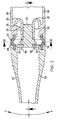
- a toothbrush 10 the brushneck 12 of which is deflectably held, in a reversible, resilient manner, on a hollow handle 14 by a swivel joint 18 surrounded by a sealing element 16.
- the brushneck 12 is provided at its coupling end 20 facing the handle 14 with an articulated head 22.
- the handle 14 exhibits at its coupling end 24 facing the brushneck 12 an articulated fork 26 having fork legs 28, 30.
- the articulated head 22 is fitted-in between the fork legs 28, 30 and connected to these by a swivel axle 32.
- the sealing element 16 is of annular configuration and consists of a pressure-elastic, rubber-like material.
- the articulated fork 26 is configured as a tension spring, such that the sealing element 16 is held by the articulated fork 26 under elastic pre-tension between the mutually opposite coupling ends 20, 24 of the brushneck 12 and of the handle 14.
- the annular sealing element 16 is provided at both ends with sealing sleeves 34, 36, which engage hermetically into recesses 38, 40 which are configured as annular grooves and which are disposed in end faces 42, 44 of the coupling ends 20, 24 of the brushneck 12 and of the handle 14.
- the sealing element 16 is provided in the centre of its width between the sealing sleeves 34, 36 with an annular sealing bead 46, the cross-sectional profile of which coincides with the cross-sectional profile of the coupling ends 20, 24 of the brushneck 12 and of the handle 14 and bears with its two end faces 48, 50 tightly against the end faces 42, 44 of the brushneck 12 and of the handle 14.
- the inner peripheral surface of the sealing bead 46 is provided with a circumferential, trough-shaped indentation 52 (Fig. 2). It can further be seen from Fig. 1 that the dividing plane between the coupling ends 20, 24 of the brushneck 12 and of the handle 14, in which plane the sealing element 16 is disposed, extends from a lower wall or front wall 56, 60 (represented in Fig. 1) of the toothbrush 10 obliquely upwards and forwards in the direction of the brushneck 12 to an upper wall or rear wall 54, 58 (shown in Fig. 1) of the said toothbrush and thus forms an acute angle with the central longitudinal axis of the toothbrush 10.
- the principal plane of the sealing element 16 also runs in this plane, so that the sealing element 16 is disposed, in the area of the rear wall 54, 58 of the toothbrush 10, closer to the front end of the brushneck 12 than the lower half facing the front wall of the toothbrush 10.
- the rear wall 54 of the brushneck 12 is shorter in size than its front wall 56, whilst the rear wall 58 of the handle 14 is longer in size than its front wall 60.
- the partially fragmented side walls of the brushneck 12 are denoted in Fig. 2 by 62, 64.
- a brushhead, connected to the brushneck 12 and having brush base and brush zone, is known per se and is not therefore represented.
- the side walls of the handle 14 are denoted by 66, 68 (Fig. 2), it being apparent that both the brushneck 12 and the handle 14 comprise hollow profiles which are injection-moulded from plastic.
- an axle 32 of the swivel joint 18 is disposed in the principal plane of the sealing element 16 close to the front side of the toothbrush 10 or of that part of the sealing element 16 which seals off the face ends of the front walls 56 or 60 of the brushneck 12 and of the handle 14.
- the above-described positions of the swivel axle 32 and of the sealing element 16 therefore enable, due to a relatively long lever arm between the swivel axle 32 and the rear wall 54, 58 of the toothbrush 10, a relatively gentle and long deflection movement of the brushneck 12.
- the articulated head 22 is formed integrally with an end wall 70 of the coupling end 20 of the brushneck 12 and protrudes axially into the cavity of the handle 14.
- the swivel axle 32 comprises two swivel journals 72, 74, which extend coaxially from the two longitudinal sides 76, 78 of the articulated head 22.
- the fork legs 28, 30 of the articulated fork 26 are respectively an integral component part of the mutually opposite side walls 66, 68 of the handle 14 and, in the area of their leg bases 80, 82, are guided out of the coupling end 24 of the handle 14 in a U-shaped formation inwardly towards each other and at a distance approximately parallel to each other.
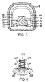
- the leg ends of the articulated fork 26 are provided with coaxial, continuous openings 84, 86 (Fig. 3), into which the swivel journals 72, 74 of the articulated head 22 engage. It can be seen that the length of the swivel journals 72, 74 corresponds approximately to the wall thickness of the fork legs 28, 30.
- the fork legs 28, 30, in the non-fitted state of the toothbrush 10, are pre-tensioned against each other, so that they form an acute angle which opens out in the direction of the rear end (not shown) of the handle. Consequently, the fork legs 28, 30, in the locked-in state of the toothbrush 10 shown in Fig. 2, bear with pre-tension against the longitudinal sides 76, 78 of the articulated head 22.
- the leg ends projecting beyond the swivel journals 72, 74 are configured on their mutually opposite inner sides as bevelled abutting surfaces 88, 90, which form with the perpendicular central longitudinal plane of the toothbrush 10 an acute angle which opens out in the direction of the brushneck 12.
- face ends 92, 94 of the swivel journals 72, 74 are also configured as abutting surfaces, which likewise form an acute angle with the perpendicular central longitudinal plane of the toothbrush, which angle opens out in the direction of the brushneck 12 and corresponds approximately to the angle formed by the abutting surfaces 88, 90 of the leg ends.
- the distance between the outer ends of the abutting surfaces 88, 90 of the fork legs 28, 30 is greater than the width of the articulated head 22 and the distance between the respective peripheral edges, facing away from the brushneck 12, of the face ends 92, 94 of the swivel journals 72, 74, it is ensured, upon the fitting of the toothbrush 10, by the coaxial bringing together of the coupling ends 20, 24 of the brushneck 12 and of the handle 14, that the articulated fork 26 is spread and the abutting surfaces 88, 90 of the fork legs 28, 30 are able to slide over the articulated head 22 and its swivel journals 72, 74 until the swivel journals 72, 74 lock into the openings 84, 86 in the articulated fork 26 and the fork legs 28, 30 bear with pre-tension against the longitudinal sides 76, 78 of the articulated head 22.
- the fork legs 28, 30 of the articulated fork 26 are disposed at a distance from the inner side of the adjacent side walls 66, 68
- the elastic, integral configuration of the articulated fork 26 with the handle 14 also allows a deflection movement in the direction of the arrows y and z in Fig. 2, which is perpendicular to the contact-pressure direction x in Fig. 1, in which direction the brushneck 12 is normally deflected when the teeth are being cleaned.
- the deflection movement in the direction of the arrows y and z in Fig. 2 is only possible to a lesser extent in relation to the deflection movement in the direction of the arrow x, but is also desirable, because unintentional jolts of the brushhead, caused by incorrect manipulation, against the denture or gum tissue are thereby damped and cleaning of the teeth is therefore made more comfortable.
- That end of the articulated head 22 which projects into the cavity of the handle 14 is provided with two stop cams 96, 98, which are disposed respectively at a distance from the inner side of the front wall 60 or of the rear wall 58 of the handle 14 for limiting the deflection movement in and counter to the direction of the arrow x of the brushneck 12.
- the distance of the stop cam 96 from the inner side of the front wall 60 is substantially greater in size than the distance which the opposite stop cam 98 adopts from the inner side of the rear wall 58, because the deflection movement counter to the direction of the arrow x, occurs, if at all, only in extremely rare cases and is basically undesirable.
- the toothbrush 10 disregarding the brushhead 10 (not shown), consists only of three parts, namely the brushneck 12, the handle 14 and the sealing element 16.
- the deflection movement in the direction of the arrow x when cleaning the teeth is cushioned by the pressure-elastic property of the sealing element 16 and the tension-spring property of the articulated fork 26, the deflection movement of the brushneck 12 being limited by the butting of the stop cam 96 against the inner side of the front wall 60.
- the elastic design of the articulated fork 26 and of the sealing element 16 additionally enable a damping of universal swivel and torsion movements of the brushneck 12, so that an overall high level of comfort is achieved with the toothbrush.
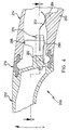
- Fig. 4 shows a second embodiment of a toothbrush 200, the reference symbols for the parts which correspond to parts of the first embodiment of the toothbrush having merely been prefixed by the number 2.
- This second embodiment differs from the first embodiment shown in Fig. 1 only by the fact that a leaf spring 202 for additional damping of the deflection movement in the direction of the arrow x of the brushneck 212 is inserted between a brushneck 212 and a handle 214.
- the leaf spring 202 is fastened in the front end, protruding into the cavity of the handle 214, of an articulated head 222 and has a curved end by which the leaf spring 202 bears upon a stop rib 204, which, as Fig.
- FIG. 5 shows, protrudes upwards from the inner side of the front wall 260 of the handle 214 in the centre and is somewhat wider in size than the leaf spring 202.
- the use of this additional leaf spring 202 can prove expedient depending upon the form and material used for an articulated fork 226 and upon the design and material of a sealing element 216.
- Fig. 6 shows a third embodiment of a toothbrush 300 according to the invention, in which the reference symbols in Fig. 1 are prefixed by the number 3 for the same or corresponding parts.
- coupling ends 320, 324 of a brushneck 312 and of a handle 314 are respectively provided with a supporting jaw 301, 303, which is in each case disposed on the inner side of a rear wall 354 of the brushneck 312 and of a rear wall 358 of the handle 314.
- these supporting jaws 301, 303 there are provided coaxially opposite-lying indentations 305, 307 for receiving the ends of a helical compression spring 309, which ends extend approximately parallel to the rear walls 354, 358 through an annular sealing element 316.
- the supporting jaw 301 of the brushneck 312 is a component part of an end wall 370 of the brushneck 312.
- an articulated head 322 is an integral component part of the end wall 370 and exhibits a lesser height merely with regard to the supporting jaw 303 of the handle 314.
- the articulated head 322 lies, as in the case of the first and second embodiments, with a stop cam 396 opposite the inner side of a front wall 360.
- the articulated head 322 is provided on its opposite side with a stop cam 398, which interacts with a stop surface 311 of the supporting jaw 303 of the handle 314, which stop surface faces the front wall 360 and runs approximately parallel to the longitudinal axis of the toothbrush 300.
- a fourth embodiment of a toothbrush 400 of the invention is represented, in which figures the reference symbols in Fig. 1 are prefixed for identical or identically operating parts by the number 4.
- This toothbrush 400 differs from the above-described embodiments essentially by the fact that a stop cam 498 projects beyond an end face 411 of an articulated head 422 on the side facing the inner side of a rear wall 458 of a handle 414, yet otherwise, as in the case of the previously described embodiments, interacts as a stop surface with the inner side of the rear wall 458.
- the end face 411 of the articulated head 422 ends at its lower end in a stop cam 496.
- the stop cam 496 lies opposite an abutting surface 425 of a U-shaped supporting rib 421 on the inner side of a front wall 460.
- the abutting surface 425 forms a stop for the stop cam 496 of the articulated head 422 in order to limit the deflection movement of the brushneck when the teeth are cleaned.
- the back of the stop cam 498, facing a front wall 460 of the handle 414, is provided with a guide shaft 413 for a compression spring 415, which is supported on the inner side of the front wall 460 of the handle 414.
- This support for the two ends of the compression spring 415 is provided by the back 416 of the stop cam 498 and by an annular supporting ring 417, which is mounted displaceably in the axial direction on a guide shaft 413 and is held by a dish-like widening 497 on the free end of the guide shaft 413.
- the supporting ring 417 exhibits a greated diameter in relation to the dish-like widening 497, so that is projects with its outer rim beyond the outer rim of the dish-like widening 497.
- a supporting rib 421 which is U-shaped in top view.
- the crosspiece of this U-shaped supporting rib 421 is denoted by 423, from which crosspiece two legs 425, 427 (Fig. 8) extend up to the end face 444 of the handle 414. It can here be seen from Fig. 7 that the supporting rib 421 exhibits the greatest height in the area of its crosspiece 423, whereas the ends of the legs 425, 427 of the U-shaped supporting rib 421 end in the plane of the inner side of the front wall 460 of the handle 414. Figs.
- FIG. 7 and 8 show that the supporting ring 417 bears with its outer rim, which radially overhangs the dish-like widening, upon the supporting rib 421, such that the dish-like widening 497 is surrounded at a distance by the supporting rib 421 and its legs 425, 427. At the same time, the dish-like widening 497, as shown in Figs.
- the U-shaped supporting rib 421 which is open in the direction of the brushneck 412, forms with its legs 425, 427, which gradually decrease in height in the direction of the ends, the oblique abutting surface 425 for the supporting ring 417 during the fitting of the toothbrush 400, a groove 428, formed by the supporting rib 421 and its legs 425, 427, forming a guide for the dish-like widening 497, until the said widening has adopted the position shown in Fig. 7 when the toothbrush 400 is fitted.
- the leaf spring and the represented helical springs consist of plastic or a corrosion-resistant metal. It can further be seen that, in all embodiments, the swivel joint is outwardly protected by the elastic sealing element and that the sealing element itself enables a hygienically satisfactory seal between the brushneck and the handle beyond the working life of the toothbrushes.
Landscapes
- Health & Medical Sciences (AREA)
- Dentistry (AREA)
- Epidemiology (AREA)
- Life Sciences & Earth Sciences (AREA)
- Animal Behavior & Ethology (AREA)
- General Health & Medical Sciences (AREA)
- Public Health (AREA)
- Veterinary Medicine (AREA)
- Brushes (AREA)
Claims (22)
- Brosse à dents (10 ; 200 ; 300 ; 400), dont le col de brosse (12 ; 212 ; 312 ; 412) , raccordé à une tête de brosse échangeable, est maintenu de façon inclinée, d'une façon élastique, réversible, sur un manche creux (14 ; 214 ; 314 ; 414), par un joint pivotant (18 ; 218 ; 318 ; 418) entouré par un élément d'étanchéité (16 ; 216 ; 316 ; 416), et par un ressort de tension se prolongeant dans le manche, le col de brosse étant équipé à son extrémité faisant face au manche, d'une tête articulée (22 ; 222 ; 322 ; 422) et le manche présentant, à son extrémité d'accouplement faisant face au col de brosse, une fourche articulée (26 ; 226 ; 326 ; 426) entre les branches (28, 30) de laquelle fourche, la tête articulée du col de brosse est insérée et raccordée par un axe de pivotement (32), caractérisée en ce que l'élément d'étanchéité (16 ; 216 ; 316 ; 416) est constitué d'une matière élastique sous une certaine pression, et en ce que la fourche articulée (26 ; 226 ; 326 ; 426) forme le ressort de tension, de sorte que l'élément d'étanchéité est maintenu par la fourche articulée sous précontrainte élastique entre les extrémités d'accouplement opposées mutuellement (20, 24 ; 220, 224 ; 320, 324 ; 420, 424) du manche (14 ; 214 ; 314 ; 414) et du col de brosse (12 ; 212 ; 312 ; 412).
- Brosse à dents selon la revendication 1, caractérisée en ce que l'élément d'étanchéité (16 ; 216 ; 316 ; 416) est annulaire et est muni aux deux extrémités de manchons d'étanchéité (34, 36 ; 234, 236 ; 334, 336 ; 434, 436), et en ce que les extrémités d'accouplement (20, 24 ; 220, 224 ; 320, 324 ; 420, 424) du manche (14 ; 214 ; 314 ; 414) et du col de brosse (12 ; 212 ; 312 ; 412) présentent des logements (38, 40 ; 238, 240 ; 338, 340 ; 438, 440) dans lesquels les manchons d'étanchéité viennent en prise de façon hermétique.
- Brosse à dents selon la revendication 2, caractérisée en ce que les logements (38, 40 ; 238, 240 ; 338, 340 ; 438, 440) destinés à recevoir les manchons d'étanchéité (34, 36 ; 234, 236 ; 334, 336 ; 434, 436) consistent en gorges annulaires qui sont disposées dans des faces d'extrémités (42, 44 ; 242, 244 ; 342, 344 ; 442, 444) des extrémités d'accouplement du manche et du col de brosse.
- Brosse à dents selon l'une quelconque des revendications 1 à 3, caractérisée en ce que l'élément d'étanchéité (16 ; 216 ; 316 ; 416) est muni au centre de sa largeur, entre les manchons d'étanchéité, d'une nervure d'étanchéité annulaire (46 ; 246 ; 346 ; 446) dont le profil en coupe transversale coïncide avec le profil en coupe transversale des extrémités d'accouplement (20, 24 ; 220, 224 ; 320, 324 ; 420, 424) du manche et du col de brosse, et porte par ses deux faces d'extrémités (48, 50 ; 248, 250 ; 348, 350 ; 448, 450) de façon hermétique contre les faces d'extrémités (42, 44 ; 242, 244 ; 342, 344 ; 442, 444) du manche et du col de brosse.
- Brosse à dents selon la revendication 4, caractérisée en ce que la surface périphérique intérieure de la nervure d'étanchéité annulaire (46 ; 246 ; 346 ; 446) présente une rainure circonférentielle (52 ; 252 ; 352 ; 452).
- Brosse à dents selon la revendication 1, caractérisée en ce que l'axe (32 ; 232 ; 332 ; 432) du joint pivotant (18 ; 218 ; 318 ; 418) est placé dans le plan principal de l'élément d'étanchéité (16 ; 216 ; 316 ; 416), proche d'une paroi avant (56, 60 ; 256, 260 ; 356, 360 ; 456, 460).
- Brosse à dents selon l'une quelconque des revendications 1 à 6, caractérisée en ce que le plan principal de l'élément d'étanchéité (16 ; 216 ; 316 ; 416) s'étend vers l'arrière depuis la face avant de la brosse à dents, obliquement par rapport à l'axe central longitudinal de la brosse à dents, vers sa paroi arrière.
- Brosse à dents selon la revendication 1, caractérisée en ce que la tête articulée (22 ; 222 ; 322 ; 422) fait saillie axialement depuis l'extrémité d'accouplement (20; 220 ; 320 ; 420) du col de brosse (12; 212 ; 312 ; 412), dans le manche (14 ; 214 ; 314 ; 414), l'axe de pivotement (32 ; 232 ; 332 ; 432) comprenant deux tourillons de pivotement (72, 74 ; 272, 274 ; 372, 374 ; 472, 474), lesquels s'étendent perpendiculairement et de façon coaxiale depuis les deux côtés longitudinaux (76, 78) de la tête articulée.
- Brosse à dents selon la revendication 1, caractérisée en ce que les branches de fourche (28, 30) de la fourche articulée (26) sont fixées sous tension élastique aux parois latérales (66, 68) mutuellement opposées du manche (14) et sont dirigées par leurs extrémités libres vers l'extrémité d'accouplement du col de brosse (12), les extrémités de branches de la fourche articulée (26) étant munies d'ouvertures continues coaxiales (84, 86) pour venir en prise avec les tourillons de pivotement (72, 74) de la tête articulée.
- Brosse à dents selon l'une des revendications 1, 8 ou 9, caractérisée en ce que les branches de fourche (28, 30) sont précontraintes l'une contre l'autre, de sorte que les branches de fourche portent avec précontrainte contre les côtés longitudinaux (76, 78) de la tête articulée (22).
- Brosse à dents selon l'une quelconque des revendications 1 ou 10, caractérisée en ce que les extrémités de branches de fourche (28, 30) sont munies de surfaces de butée (88, 90) biseautée, mutuellement opposées, la plus grande distance libre entre celles-ci est plus grande en dimension que la distance entre les extrémités des faces biseautées correspondantes (92, 94) des deux tourillons de pivotement (72, 74).
- Brosse à dents selon l'une quelconque des revendications 8 à 10, caractérisée en ce que la longueur de chaque tourillon de pivotement (72, 74) correspond approximativement à l'épaisseur des branches plates (28, 30) de la fourche articulée (26), les branches de fourche étant placées à une certaine distance du côté intérieur des parois latérales adjacentes (66, 68) du manche (14) qui correspond au moins à l'épaisseur d'une branche de fourche.
- Brosse à dents selon l'une quelconque des revendications 1 à 12, caractérisée en ce que l'extrémité de la tête articulée (22) qui fait saillie à l'intérieur d'une cavité du manche (14) est munie de deux cames d'arrêt (96, 98) qui sont placées, respectivement, à une certaine distance du côté intérieur d'une paroi avant (60) ou d'une paroi arrière (58) du manche (14) pour limiter le fléchissement du col de brosse (12).
- Brosse à dents selon l'une quelconque des revendications 1 à 12, caractérisée en ce qu'un ressort (202 ; 309 ; 415), pour un amortissement supplémentaire du fléchissement du col de brosse (12) est inséré entre le manche (214 ; 314 ; 414) et le col de brosse (212 ; 312 ; 412).
- Brosse à dents selon la revendication 14, caractérisée en ce que le ressort supplémentaire (202) est un ressort à lame dont une extrémité est fixée à l'extrémité libre de la tête articulée (222) en saillie dans le manche (214) et dont l'autre extrémité est appuyée sur une nervure support (204) de la paroi avant (260) du manche (214).
- Brosse à dents selon l'une quelconque des revendications 1 à 14, caractérisée en ce qu'une mâchoire support (301, 303) est, dans chaque cas, placée sur le côté intérieur de la paroi arrière (354, 358) du col de brosse (312) et du manche (314) au voisinage de leurs extrémités d'accouplement (320, 324), dans lesquelles sont prévues des rainures (305, 307), opposées de façon coaxiale, destinées à recevoir les extrémités du ressort, sous forme d'un ressort de compression (309) qui s'étend à travers l'élément d'étanchéité (316).
- Brosse à dents selon la revendication 16, caractérisée en ce que la mâchoire support (303) forme, sur le côté intérieur de la paroi arrière (358) du manche (314), une surface de butée (311) pour la came d'arrêt (398), se trouvant à l'opposé, à une certaine distance, de la tête articulée.
- Brosse à dents selon l'une quelconque des revendications 1 à 14, caractérisée en ce que la came d'arrêt (498) se trouvant à l'opposé du côté intérieur de la paroi arrière (458) du manche (414) fait saillie au-delà de la face d'extrémité de la tête articulée (422), l'arrière de la came d'arrêt (498), faisant face à la paroi avant (460), étant muni d'une tige de guidage (413) pour un ressort de compression hélicoïdal (415), laquelle tige de guidage est réalisée, à son extrémité se trouvant à une certaine distance à l'opposé du côté intérieur de la paroi avant (460), sous forme d'un élargissement en forme de cuvette (497).
- Brosse à dents selon la revendication 18, caractérisée en ce qu'un anneau support (417) est monté de façon mobile sur la tige de guidage (413) de la tête articulée (422) et est maintenu par l'élargissement en forme de cuvette (497) sur l'extrémité libre de la tige de guidage (413), le ressort de compression hélicoïdal (415) étant supporté à ses deux extrémités contre l'arrière de la came d'arrêt (498) se trouvant à l'opposé de la paroi arrière (458) et sur l'anneau support (417).
- Brosse à dents selon la revendication 19, caractérisée en ce que l'anneau support (417) présente un rebord extérieur qui fait saillie radialement au-dessus de l'élargissement en forme de cuvette (497), et en ce que, sur le côté intérieur de la paroi avant (460) du manche (414), est placée une nervure support (421), sur laquelle l'anneau support (417) porte par son rebord extérieur, la nervure support (421) entourant l'élargissement en forme de cuvette (497) sur une certaine distance radiale.
- Brosse à dents selon la revendication 20, caractérisée en ce que la nervure support (421) sur le côté intérieur de la paroi avant (460) du manche (414) est en forme de U en vue de dessus, le rebord extérieur de l'anneau support (417) portant sur un élément transversal (423) et sur des parties attenantes des branches (425, 427) de la nervure support (421).
- Brosse à dents selon la revendication 21, caractérisée en ce que les branches (425, 427) sont inclinées dans la direction de la face d'extrémité (444) du manche (414) et forment une surface de butée, quand la brosse à dents est insérée, pour l'anneau support (417) et un dispositif d'arrêt pour une came d'arrêt (496) de la tête articulée (422) afin de limiter le mouvement de fléchissement du col de brosse (412).
Applications Claiming Priority (2)
| Application Number | Priority Date | Filing Date | Title |
|---|---|---|---|
| DE4242355 | 1992-12-15 | ||
| DE4242355A DE4242355C1 (de) | 1992-12-15 | 1992-12-15 | Zahnbürste |
Publications (2)
| Publication Number | Publication Date |
|---|---|
| EP0602611A1 EP0602611A1 (fr) | 1994-06-22 |
| EP0602611B1 true EP0602611B1 (fr) | 1996-09-25 |
Family
ID=6475359
Family Applications (1)
| Application Number | Title | Priority Date | Filing Date |
|---|---|---|---|
| EP93120157A Expired - Lifetime EP0602611B1 (fr) | 1992-12-15 | 1993-12-14 | Brosse à dents |
Country Status (10)
| Country | Link |
|---|---|
| US (1) | US5707166A (fr) |
| EP (1) | EP0602611B1 (fr) |
| JP (1) | JP3399611B2 (fr) |
| KR (1) | KR100232786B1 (fr) |
| AT (1) | ATE143232T1 (fr) |
| AU (1) | AU673016B2 (fr) |
| CA (1) | CA2110861C (fr) |
| DE (2) | DE4242355C1 (fr) |
| GR (1) | GR1002543B (fr) |
| HK (1) | HK1997A (fr) |
Cited By (3)
| Publication number | Priority date | Publication date | Assignee | Title |
|---|---|---|---|---|
| EP2807948A1 (fr) | 2013-05-29 | 2014-12-03 | The Gillette Company | Procédé pour produire une brosse à dents et brosse à dents ainsi produite |
| EP2807946A1 (fr) | 2013-05-29 | 2014-12-03 | The Gillette Company | Concept de brosse à dents manuelle combinée à partir de trois parties |
| US9717324B2 (en) | 2013-05-29 | 2017-08-01 | The Gillette Company Llc | Method for producing a toothbrush and toothbrush produced thereby |
Families Citing this family (15)
| Publication number | Priority date | Publication date | Assignee | Title |
|---|---|---|---|---|
| DE4409817C1 (de) * | 1994-03-22 | 1995-07-27 | Johnson & Johnson Ag | Zahnbürste |
| KR20010030722A (ko) * | 1997-09-26 | 2001-04-16 | 맨프레드 쉬에스케 | 치솔 |
| IT1318525B1 (it) * | 2000-05-18 | 2003-08-27 | Ponzini Spa | Spazzolino scomponibile a bloccaggio attivo. |
| US7281289B1 (en) | 1999-09-17 | 2007-10-16 | Placontrol, Inc. | Automatic pressure release toothbrush |
| WO2001021035A1 (fr) * | 1999-09-17 | 2001-03-29 | Placontrol, Inc. | Brosse a dents a relachement de pression automatique ii/iii |
| US6883200B1 (en) * | 1999-10-01 | 2005-04-26 | Heinrich Georg Euler | Tooth brush |
| DE10005738A1 (de) * | 2000-02-09 | 2001-08-23 | Trisa Holding Ag Triengen | Verfahren zum Herstellen eines hohlen Handgriffes für Körperpflegegerät |
| USD475530S1 (en) | 2000-04-04 | 2003-06-10 | Munchkin, Inc. | Toothbrush |
| US6502272B1 (en) * | 2000-05-24 | 2003-01-07 | Colgate-Palmolive Company | Replaceable head toothbrush providing controlled brushing pressure |
| USD458757S1 (en) | 2001-01-31 | 2002-06-18 | Munchkin, Inc. | Toothbrush |
| US20070261963A1 (en) * | 2006-02-02 | 2007-11-15 | Advanced Technology Materials, Inc. | Simultaneous inorganic, organic and byproduct analysis in electrochemical deposition solutions |
| RU2428907C2 (ru) | 2007-02-02 | 2011-09-20 | Дзе Жиллетт Компани | Принадлежности для гигиены полости рта, имеющие гибкие элементы, и способы их изготовления |
| KR100966828B1 (ko) | 2008-01-18 | 2010-06-28 | (주)상문 | 칫솔모 교체용 칫솔 |
| US20110016651A1 (en) * | 2009-07-21 | 2011-01-27 | Robert Piserchio | Pressure-sensitive toothbrush |
| EP2407123A1 (fr) * | 2010-07-17 | 2012-01-18 | Braun GmbH | Appareil électrique pour utilisation personnelle |
Family Cites Families (18)
| Publication number | Priority date | Publication date | Assignee | Title |
|---|---|---|---|---|
| US759490A (en) * | 1902-12-08 | 1904-05-10 | Florence Mfg Company | Tooth-brush. |
| US1887913A (en) * | 1932-01-09 | 1932-11-15 | Harry D Bell | Toothbrush |
| US2130661A (en) * | 1933-11-14 | 1938-09-20 | John Vanderkamp | Tooth brush |
| US2832943A (en) * | 1954-12-09 | 1958-04-29 | Cutler Morris | Detachable coupling |
| GB2044089A (en) * | 1979-03-02 | 1980-10-15 | Kent & Sons Ltd G B | Disposable head toothbrush |
| FR2509154B1 (fr) * | 1981-07-13 | 1989-06-02 | Massari B | Brosse a dent, a tete presentant un angle diversifie |
| US4476604A (en) * | 1983-05-27 | 1984-10-16 | Larry W. White | Pressure sensing device for holding a toothbrush |
| FR2550068B1 (fr) * | 1983-08-05 | 1987-06-05 | Fabre Sa Pierre | Brosse a dents articulee |
| CA1251610A (fr) * | 1984-08-14 | 1989-03-28 | Hiroshi Hukuba | Brosse a dents electrique |
| US4829621A (en) * | 1986-07-09 | 1989-05-16 | Phenegar John S | Toothbrush |
| WO1988006417A1 (fr) * | 1987-02-27 | 1988-09-07 | Blendax-Werke R. Schneider Gmbh & Co. | Brosse a dents |
| US4798492A (en) * | 1987-12-07 | 1989-01-17 | Smith Thomas R | Shaft coupling and method for using same |
| GB8807673D0 (en) * | 1988-03-31 | 1988-05-05 | Lingner & Fischer Gmbh | Novel article |
| DE3921371C1 (en) * | 1989-06-29 | 1990-08-30 | Josef 7888 Rheinfelden De Scheller | Tooth brush with resiliently deflectable brush head - has swivel joint above tensile spring fastening point, as bolt through head facing end of handle |
| DE3923495C1 (fr) * | 1989-07-15 | 1991-01-24 | M + C Schiffer Gmbh, 5466 Neustadt, De | |
| DE3937877C1 (en) * | 1989-11-14 | 1991-04-04 | Braun Ag, 6000 Frankfurt, De | Electric tooth-brush with cap sealing mounted by arresting ring - protected against knocks or vibration of drive since inner housing is spaced from outer by star-shaped bridging piece |
| US5105499A (en) * | 1991-03-01 | 1992-04-21 | The Procter & Gamble Company | Toothbrush having handle joined to brush head by non-pinching flexible twin beam structure |
| US5282291A (en) * | 1992-09-16 | 1994-02-01 | Bioware Inc. | Force sensitive handle for hand operated implement |
-
1992
- 1992-12-15 DE DE4242355A patent/DE4242355C1/de not_active Expired - Fee Related
-
1993
- 1993-12-01 AU AU52097/93A patent/AU673016B2/en not_active Ceased
- 1993-12-07 CA CA002110861A patent/CA2110861C/fr not_active Expired - Fee Related
- 1993-12-08 GR GR930100495A patent/GR1002543B/el not_active IP Right Cessation
- 1993-12-14 DE DE69305055T patent/DE69305055T2/de not_active Expired - Fee Related
- 1993-12-14 EP EP93120157A patent/EP0602611B1/fr not_active Expired - Lifetime
- 1993-12-14 AT AT93120157T patent/ATE143232T1/de not_active IP Right Cessation
- 1993-12-14 JP JP34212593A patent/JP3399611B2/ja not_active Expired - Fee Related
- 1993-12-15 KR KR1019930027737A patent/KR100232786B1/ko not_active Expired - Fee Related
-
1997
- 1997-01-02 HK HK1997A patent/HK1997A/en not_active IP Right Cessation
- 1997-01-24 US US08/788,583 patent/US5707166A/en not_active Expired - Lifetime
Cited By (5)
| Publication number | Priority date | Publication date | Assignee | Title |
|---|---|---|---|---|
| EP2807948A1 (fr) | 2013-05-29 | 2014-12-03 | The Gillette Company | Procédé pour produire une brosse à dents et brosse à dents ainsi produite |
| EP2807946A1 (fr) | 2013-05-29 | 2014-12-03 | The Gillette Company | Concept de brosse à dents manuelle combinée à partir de trois parties |
| EP2807947A1 (fr) | 2013-05-29 | 2014-12-03 | The Gillette Company | Concept de brosse à dents manuelle combinée en trois parties |
| US9486066B2 (en) | 2013-05-29 | 2016-11-08 | The Gillette Company | Manual toothbrush concept being combined from three parts |
| US9717324B2 (en) | 2013-05-29 | 2017-08-01 | The Gillette Company Llc | Method for producing a toothbrush and toothbrush produced thereby |
Also Published As
| Publication number | Publication date |
|---|---|
| DE69305055T2 (de) | 1997-02-06 |
| GR1002543B (el) | 1997-01-27 |
| KR940013417A (ko) | 1994-07-15 |
| AU673016B2 (en) | 1996-10-24 |
| JPH07226A (ja) | 1995-01-06 |
| DE69305055D1 (de) | 1996-10-31 |
| ATE143232T1 (de) | 1996-10-15 |
| EP0602611A1 (fr) | 1994-06-22 |
| HK1997A (en) | 1997-01-10 |
| JP3399611B2 (ja) | 2003-04-21 |
| US5707166A (en) | 1998-01-13 |
| DE4242355C1 (de) | 1994-02-17 |
| CA2110861A1 (fr) | 1994-06-16 |
| GR930100495A (el) | 1994-08-31 |
| KR100232786B1 (ko) | 1999-12-01 |
| CA2110861C (fr) | 2005-03-08 |
| AU5209793A (en) | 1994-06-30 |
Similar Documents
| Publication | Publication Date | Title |
|---|---|---|
| EP0602611B1 (fr) | Brosse à dents | |
| EP1229811B1 (fr) | Brosse a dents | |
| FI109175B (fi) | Hammasharja, jonka päässä on taipuvasti liitetty alue | |
| KR100253963B1 (ko) | 탄력적인 가요성 강모-함유 헤드를 갖는 칫솔 | |
| US10869743B2 (en) | Electric toothbrush | |
| EP1237438B1 (fr) | Brosse a dents | |
| US8209808B2 (en) | Toothbrush and attachment therefor | |
| AU2003255245B2 (en) | Toothbrush | |
| US6668415B2 (en) | Toothbrush | |
| ZA200209064B (en) | Toothbrush. | |
| MX2014000416A (es) | Cepillo de dientes y cabeza de repuesto para el mismo. | |
| CA2749801A1 (fr) | Brosse a dents a cou flexible | |
| CN116546904A (zh) | 口腔护理器具 | |
| WO1998034513A1 (fr) | Brosse a dents | |
| CA2618892C (fr) | Brosse a dents comportant des elements de nettoyage mobiles et fixes | |
| RU2108054C1 (ru) | Зубная щетка | |
| EP1459649B1 (fr) | Brosse a dants | |
| KR200224272Y1 (ko) | 치약내장형칫솔 | |
| KR200321486Y1 (ko) | 칫솔 | |
| KR100343901B1 (ko) | 칫솔 | |
| NZ614282A (en) | Toothbrush with a flexible region in the handle | |
| NZ614282B2 (en) | Toothbrush with a flexible region in the handle |
Legal Events
| Date | Code | Title | Description |
|---|---|---|---|
| PUAI | Public reference made under article 153(3) epc to a published international application that has entered the european phase |
Free format text: ORIGINAL CODE: 0009012 |
|
| AK | Designated contracting states |
Kind code of ref document: A1 Designated state(s): AT CH DE GB IT LI SE |
|
| 17P | Request for examination filed |
Effective date: 19941130 |
|
| GRAG | Despatch of communication of intention to grant |
Free format text: ORIGINAL CODE: EPIDOS AGRA |
|
| 17Q | First examination report despatched |
Effective date: 19951219 |
|
| GRAH | Despatch of communication of intention to grant a patent |
Free format text: ORIGINAL CODE: EPIDOS IGRA |
|
| GRAH | Despatch of communication of intention to grant a patent |
Free format text: ORIGINAL CODE: EPIDOS IGRA |
|
| GRAA | (expected) grant |
Free format text: ORIGINAL CODE: 0009210 |
|
| AK | Designated contracting states |
Kind code of ref document: B1 Designated state(s): AT CH DE GB IT LI SE |
|
| REF | Corresponds to: |
Ref document number: 143232 Country of ref document: AT Date of ref document: 19961015 Kind code of ref document: T |
|
| REG | Reference to a national code |
Ref country code: CH Ref legal event code: NV Representative=s name: E. BLUM & CO. PATENTANWAELTE |
|
| REF | Corresponds to: |
Ref document number: 69305055 Country of ref document: DE Date of ref document: 19961031 |
|
| ITF | It: translation for a ep patent filed | ||
| PLBE | No opposition filed within time limit |
Free format text: ORIGINAL CODE: 0009261 |
|
| STAA | Information on the status of an ep patent application or granted ep patent |
Free format text: STATUS: NO OPPOSITION FILED WITHIN TIME LIMIT |
|
| 26N | No opposition filed | ||
| REG | Reference to a national code |
Ref country code: GB Ref legal event code: IF02 |
|
| PGFP | Annual fee paid to national office [announced via postgrant information from national office to epo] |
Ref country code: SE Payment date: 20061206 Year of fee payment: 14 |
|
| PGFP | Annual fee paid to national office [announced via postgrant information from national office to epo] |
Ref country code: DE Payment date: 20061207 Year of fee payment: 14 |
|
| PGFP | Annual fee paid to national office [announced via postgrant information from national office to epo] |
Ref country code: GB Payment date: 20061213 Year of fee payment: 14 Ref country code: CH Payment date: 20061213 Year of fee payment: 14 Ref country code: AT Payment date: 20061213 Year of fee payment: 14 |
|
| PGFP | Annual fee paid to national office [announced via postgrant information from national office to epo] |
Ref country code: IT Payment date: 20061231 Year of fee payment: 14 |
|
| REG | Reference to a national code |
Ref country code: CH Ref legal event code: PFA Owner name: JOHNSON & JOHNSON CONSUMER PRODUCTS, INC. Free format text: JOHNSON & JOHNSON CONSUMER PRODUCTS, INC.#GRANDVIEW ROAD#SKILLMAN, NEW JERSEY 08558-9418 (US) -TRANSFER TO- JOHNSON & JOHNSON CONSUMER PRODUCTS, INC.#GRANDVIEW ROAD#SKILLMAN, NEW JERSEY 08558-9418 (US) |
|
| REG | Reference to a national code |
Ref country code: CH Ref legal event code: PL |
|
| EUG | Se: european patent has lapsed | ||
| GBPC | Gb: european patent ceased through non-payment of renewal fee |
Effective date: 20071214 |
|
| PG25 | Lapsed in a contracting state [announced via postgrant information from national office to epo] |
Ref country code: AT Free format text: LAPSE BECAUSE OF NON-PAYMENT OF DUE FEES Effective date: 20071214 |
|
| PG25 | Lapsed in a contracting state [announced via postgrant information from national office to epo] |
Ref country code: DE Free format text: LAPSE BECAUSE OF NON-PAYMENT OF DUE FEES Effective date: 20080701 Ref country code: CH Free format text: LAPSE BECAUSE OF NON-PAYMENT OF DUE FEES Effective date: 20071231 Ref country code: SE Free format text: LAPSE BECAUSE OF NON-PAYMENT OF DUE FEES Effective date: 20071215 Ref country code: LI Free format text: LAPSE BECAUSE OF NON-PAYMENT OF DUE FEES Effective date: 20071231 |
|
| PG25 | Lapsed in a contracting state [announced via postgrant information from national office to epo] |
Ref country code: GB Free format text: LAPSE BECAUSE OF NON-PAYMENT OF DUE FEES Effective date: 20071214 |
|
| PG25 | Lapsed in a contracting state [announced via postgrant information from national office to epo] |
Ref country code: IT Free format text: LAPSE BECAUSE OF NON-PAYMENT OF DUE FEES Effective date: 20071214 |