EP0602645B1 - Procédé et appareil de régulation de température dans une installation de chauffage et réfrigération à effet Peltier - Google Patents
Procédé et appareil de régulation de température dans une installation de chauffage et réfrigération à effet Peltier Download PDFInfo
- Publication number
- EP0602645B1 EP0602645B1 EP93120327A EP93120327A EP0602645B1 EP 0602645 B1 EP0602645 B1 EP 0602645B1 EP 93120327 A EP93120327 A EP 93120327A EP 93120327 A EP93120327 A EP 93120327A EP 0602645 B1 EP0602645 B1 EP 0602645B1
- Authority
- EP
- European Patent Office
- Prior art keywords
- temperature
- value
- max
- actual
- peltier element
- Prior art date
- Legal status (The legal status is an assumption and is not a legal conclusion. Google has not performed a legal analysis and makes no representation as to the accuracy of the status listed.)
- Expired - Lifetime
Links
- 238000001816 cooling Methods 0.000 title claims description 13
- 238000000034 method Methods 0.000 title claims description 12
- 238000010438 heat treatment Methods 0.000 title claims description 9
- 238000009434 installation Methods 0.000 title 1
- 238000010586 diagram Methods 0.000 description 4
- 238000006243 chemical reaction Methods 0.000 description 2
- 230000001419 dependent effect Effects 0.000 description 2
- 230000002093 peripheral effect Effects 0.000 description 2
- 230000001105 regulatory effect Effects 0.000 description 2
- 230000005679 Peltier effect Effects 0.000 description 1
- 230000000712 assembly Effects 0.000 description 1
- 238000000429 assembly Methods 0.000 description 1
- 238000004891 communication Methods 0.000 description 1
- 238000009795 derivation Methods 0.000 description 1
- 230000000694 effects Effects 0.000 description 1
- 238000009499 grossing Methods 0.000 description 1
- 230000017525 heat dissipation Effects 0.000 description 1
- 230000001939 inductive effect Effects 0.000 description 1
- 239000007788 liquid Substances 0.000 description 1
- 238000012544 monitoring process Methods 0.000 description 1
- 238000011084 recovery Methods 0.000 description 1
- 230000000630 rising effect Effects 0.000 description 1
- 230000005676 thermoelectric effect Effects 0.000 description 1
Images


Classifications
-
- G—PHYSICS
- G05—CONTROLLING; REGULATING
- G05D—SYSTEMS FOR CONTROLLING OR REGULATING NON-ELECTRIC VARIABLES
- G05D23/00—Control of temperature
- G05D23/19—Control of temperature characterised by the use of electric means
- G05D23/1919—Control of temperature characterised by the use of electric means characterised by the type of controller
-
- F—MECHANICAL ENGINEERING; LIGHTING; HEATING; WEAPONS; BLASTING
- F25—REFRIGERATION OR COOLING; COMBINED HEATING AND REFRIGERATION SYSTEMS; HEAT PUMP SYSTEMS; MANUFACTURE OR STORAGE OF ICE; LIQUEFACTION SOLIDIFICATION OF GASES
- F25B—REFRIGERATION MACHINES, PLANTS OR SYSTEMS; COMBINED HEATING AND REFRIGERATION SYSTEMS; HEAT PUMP SYSTEMS
- F25B2321/00—Details of machines, plants or systems, using electric or magnetic effects
- F25B2321/02—Details of machines, plants or systems, using electric or magnetic effects using Peltier effects; using Nernst-Ettinghausen effects
- F25B2321/021—Control thereof
- F25B2321/0212—Control thereof of electric power, current or voltage
Definitions
- the invention relates to a method and a control device for temperature control in a heating and / or cooling device equipped with at least one Peltier element, in which the difference between a target temperature value and a measured actual temperature value on the cold side of the Peltier Elements determines the current for the Peltier element via a PID controlled system.
- thermoelectric effect By using the thermoelectric effect according to Peltier operated cooling and / or heating devices, of which temperature chambers or temperature test chambers may be an example, are characterized, among other things, by the fact that certain predeterminable temperature values are set very precisely and can be held.
- the temperature controls intended for such devices are generally designed to maintain a defined, very constant temperature, such as that used to temper electronic components such as laser diodes (to keep the wavelength constant).
- Microprocessors to achieve higher clock rates
- certain electronic assemblies and devices to increase reliability
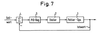
- FIG. 7 of the accompanying drawings shows a typical control device for a Peltier heating / cooling chamber with an input side via a difference generator 4 by the difference between a predeterminable temperature setpoint and a temperature measured on the Peltier elements 1 on the cold side Actual value of the PID controlled system 3.
- the PID controller 3 supplies a control voltage to an actuating device 2, for example a voltage-controllable constant current source, which determines the current value for the Peltier system 1, which generally consists of several electrically connected Peltier elements .
- PID controlled systems of the known type generally work satisfactorily. For many applications, however, the possible temperature range is too small, in particular because the power loss "to be pumped away" via the Peltier elements is insufficient.
- the invention is therefore based on the object of providing a method and a regulating device for Peltier elements to be actively supplied with a direct current within a heating / cooling system, by means of which the possible temperature range can be expanded considerably while at the same time improving the heat pump performance.
- the invention is characterized according to the invention in a method for temperature control according to the type mentioned at the outset in that the hot side temperature of the Peltier element (s) is measured and the temperature difference value between the hot side temperature and the (cold side) actual temperature value is determined and the difference value is compared against a maximum permissible temperature difference between the hot and cold side of the Peltier element (s) and that a temperature target value specified for a desired operating temperature is used as the temperature setpoint, as long as the maximum permissible temperature difference is minus of a fixed small temperature hysteresis value is greater than the temperature difference value, while the temperature setpoint is equated with the actual temperature value as soon as the temperature difference value becomes equal to or greater than the maximum permissible temperature difference plus the temperature hysteresis value.
- the maximum permissible temperature difference value is generally dependent on the warm side temperature of the Peltier elements and is advantageously taken from a storage table for feeding into the control loop.
- a control device for temperature control in a heating and / or cooling device equipped with at least one Peltier element and having an internal control loop, which essentially corresponds to the control loop according to FIG. 7, is characterized according to the invention by the hot side temperature of the Peltier element (the Peltier Elements) detecting temperature sensor, a comparator that calculates the difference between the hot side temperature value and the cold side temperature actual value and compares it to a maximum permissible temperature difference value, and by a setpoint switch controlled by the comparator, which then switches a predetermined temperature target value to the difference generator when the maximum permissible temperature difference value, minus a fixed, small temperature hysteresis value, is greater than the difference value and the difference generator is acted upon by the cold side temperature actual value as soon as the comparator has determined that the diff value is greater than the maximum permissible temperature difference value plus the temperature hysteresis value.
- the invention makes use of the knowledge that for each Peltier element there is a maximum temperature difference ⁇ T max between the temperature on the heat-emitting side and the heat-absorbing side (cold side) of the Peltier element, which is dependent on the operating current and the absolute hot side temperature.
- the maximum temperature difference value .DELTA.T max is given in each case for different warm side temperatures in the characteristic curve fields issued by manufacturers of Peltier elements, of which FIG. 3 gives an example.
- variable ⁇ T max is regulated.
- the warm side temperature T 2 is used as an additional measured variable.
- the Peltier element system 1 supplied via the PID controller 3 and the voltage-controllable constant current source 2 is present, the input of the PID controller 3 being acted upon by a difference generator 4 is the difference value between a predefined temperature setpoint and the measured on the cold side of the Peltier element temperature is determined.
- a comparator 6, a setpoint switch 5 and a temperature sensor 7 for detecting the warm side temperature T 2 of the Peltier elements have been added as additional elements.
- the actual temperature PID controller remains as an internal control loop.
- One setpoint T target is specified by the user either via an actuator or preferably via a control program in accordance with the values stored in a register.
- the target value switch 5 has the task of, in accordance with the specification by the decision signal from the comparator 6, either a target value T target, or the cold side temperature value T is to be determined as a target value for the inner loop.
- the target value switch 5 is on the circuit on the cold side temperature value T does not immediately switch back to the default value T target, it is necessary to add a small Hysteresetemperaturwert reduce in particular in a heat sink on the cold side accumulated heat.
- the size of this hysteresis value depends on the heat capacity of the selected heat sink. In principle, the higher the thermal capacity, the higher the hysteresis temperature should be selected.
- the hysteresis temperature value T h is ⁇ 1.0 ° C, for example ⁇ 0.2 to ⁇ 0.3 ° C.
- the maximum possible temperature difference ⁇ T between the hot and the cold side of the Peltier elements increases with the increase in the hot side temperature T 2 . It follows from that with the invention applied knowledge that the specification for the maximum temperature difference ⁇ T max is to be influenced as a function of T 2 .
- the ⁇ T max preset values depending on the hot side temperature values T 2 for a possible temperature range, can be pre-stored in a so-called “look-up table” and the comparator 6 can be specified as a function of the respective hot side temperature T 2 .
- This first possibility is particularly suitable for a software solution of the control algorithm using a microprocessor, of which the arrangement of FIG. 2 explained below provides an example.
- the values for ⁇ T max can be specified precisely with a sufficiently fine gradation, since non-linearities can also be taken into account. In practice, however, it has been shown that the derivation of ⁇ T max from the linear relationship given provides sufficiently precise default values for ⁇ T max .
- FIG. 2 shows the basic block diagram of a complete system of a temperature chamber with a Peltier element system 1 (Peltier pump), a heat exchanger 17 connected in intimate heat-conducting contact with the Peltier elements with an associated circulating cooler 14, a temperature sensor 18 for the cold sides Actual temperature T 1 and the temperature sensor 7 for the warm side temperature T 2 .
- Peltier element system 1 Peltier pump
- a heat exchanger 17 connected in intimate heat-conducting contact with the Peltier elements with an associated circulating cooler 14
- a temperature sensor 18 for the cold sides Actual temperature T 1 and the temperature sensor 7 for the warm side temperature T 2 .
- the temperature control circuit expanded according to the invention is constructed in the form of a control algorithm controlled by a microprocessor 9.
- the microprocessor 9 are after analog / digital conversion in one A / D converter 8, in addition to the actual cold side temperature T 1, also the temperature values T 2 of the heat sink at the heat exchanger 17.
- the microprocessor 9 supplies the controller output signal provided by the digital-to-analog converter via a D / A converter 15 to the voltage-controllable constant current source 2.
- the current supplied by the constant current source 2 acts on the elements of the Peltier system 1 via a preferably inductive smoothing device 16.
- the supply current supply for the constant current source 2 and the circulating cooler 14, which is usually supplied with mains current, supplies a transformer and conversion unit 13.
- the microprocessor 9 supplies control signal data to a peripheral computer unit 10. Communication with the microprocessor 9 takes place via a keypad 11. Various control values can be found within the overall arrangement represent a display panel 12.
- the controller software works according to a subroutine which is illustrated by the flow chart in FIG. 4 and no further explanation is required for the person skilled in the art.
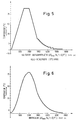
- 5 and 6 show the typical measured temperature curve using a controller system according to the invention.
- step-like "recovery breaks" of the system can be seen, which, however, have no effect on the interior temperature of the temperature chamber due to thermal inertia.
- the measured curves show, when using the control according to the invention, a minimum temperature of approximately -15 ° C. is reached for the selected default values. Without the ⁇ T max control according to the invention, only minimum temperatures of approximately +5 ° C. can be achieved. If, in deviation from the software-programmed solution with a microprocessor according to FIG. 2, the control loop according to FIG. 1 expanded according to the invention is constructed “in terms of hardware”, then a commercially available temperature controller can be assumed.
- the switching threshold is to be determined and programmed empirically with regard to the required hysteresis.
- a setpoint ramp generator is required, for example in connection with the limit comparator with control input for START / STOP of the ramp. The signal of the setpoint ramp generator, which specifies a temperature ramp, is stopped when a hot side limit temperature is exceeded and released again when the temperature falls below the limit.
Landscapes
- Physics & Mathematics (AREA)
- General Physics & Mathematics (AREA)
- Engineering & Computer Science (AREA)
- Automation & Control Theory (AREA)
- Control Of Temperature (AREA)
Claims (7)
- Procédé de régulation de température dans une installation de chauffage et/ou de réfrigération équipée d'au moins un élément Peltier, dans lequel la différence entre une valeur de consigne de la température et une valeur effective mesurée (Tist) de la température détermine sur le côté froid de l'élément Peltier, par l'intermédiaire d'un système de régulation PID, le courant pour l'élément Peltier, caractérisé en ce que- l'on mesure la température du côté chaud (T2) de l'élément Peltier et détermine la différence de température entre la température du côté chaud (T2) et la valeur effective de la température (du côté froid) (Tist),- la différence de température (ΔT = T2 - Tist) est comparée avec la différence de température maximale admissible (ΔTmax) entre le côté chaud et le côté froid de l'élément Peltier, et que- l'on utilise comme valeur de consigne de la température une valeur de température cible (Tziel) prédéterminée pour une température de fonctionnement désirée, aussi longtemps que la différence de température maximale admissible (ΔTmax) moins une faible valeur d'hystérésis fixe de la température (Th) est supérieure à la différence de température (ΔT), alors que la valeur de consigne de la température (Tsoll) est égalée à la valeur effective de la température (Tist) dès que la différence de température est égale ou supérieure à la différence de température maximale admissible (ΔTmax) plus la valeur d'hystérésis de la température (Th).
- Procédé selon la revendication 1, caractérisé en ce que la différence de température maximale admissible (ΔTmax) est prédéterminée en fonction de la température du côté chaud (T2).
- Procédé selon la revendication 1, caractérisé en ce que la différence de température maximale admissible (ΔTmax) est déterminée, en fonction de la température du côté chaud (T2), dans une table de mémoire.
- Procédé selon l'une des revendications précédentes, caractérisé en ce que le courant pour l'élément Peltier est limité à une valeur de courant optimale (Iopt) qui est nécessaire pour maintenir la température la plus basse possible au maximum pour l'élément Peltier.
- Dispositif de réglage pour la régulation de température dans une installation de chauffage et/ou de réfrigération équipée d'au moins un élément Peltier, comprenant- un régulateur PID (3) à l'entrée duquel est transmise, à partir de la sortie d'un différenciateur (4), la différence entre une valeur de consigne prédéterminable de la température et une valeur effective mesurée (Tist) de la température du côté froid de l'élément Peltier, et- une source de courant constant (2) commandée par le régulateur PID (3), dont la tension peut être commandée et qui détermine le courant d'alimentation pour l'élément Peltier,caractérisé en ce qu'il comprend- un détecteur de température (7) qui enregistre la température du côté chaud (T2) de l'élément Peltier (1),- un comparateur (6) qui calcule la différence de température (ΔT) entre la valeur de température du côté chaud (T2) et la valeur effective (Tist) de la température du côté froid et la compare avec une différence de température maximale admissible (ΔTmax), et- un commutateur de valeur de consigne (5) commandé par le comparateur (6), qui envoie une valeur de température cible (Tziel) au différenciateur (4) si la différence de température maximale admissible (ΔTmax) moins une faible valeur d'hystérésis fixe de la température (Th) est supérieure à la différence de température (ΔT), et qui envoie au différenciateur (4) la valeur effective (Tist) de la température du coté froid dès que le comparateur (6) a établi que la différence de température est supérieure ou égale à la différence de température maximale admissible (ΔTmax) plus la valeur d'hystérésis de la température (Th).
- Dispositif de réglage selon la revendication 5, caractérisé en ce que la différence de température maximale admissible (ΔTmax) prédéterminée sur le comparateur (6) est déterminée à partir de la relation

- Dispositif de réglage selon la revendication 6, caractérisé en ce que les opérations de réglage sont implémentées dans un microprocesseur (9), et que la différence de température maximale admissible (ΔTmax) peut être appelée dans une table de mémoire préprogrammée.
Applications Claiming Priority (2)
| Application Number | Priority Date | Filing Date | Title |
|---|---|---|---|
| DE4242841A DE4242841C2 (de) | 1992-12-17 | 1992-12-17 | Verfahren und Regeleinrichtung zur Temperaturregelung für ein peltierbetriebenes Temperiergerät |
| DE4242841 | 1992-12-17 |
Publications (2)
| Publication Number | Publication Date |
|---|---|
| EP0602645A1 EP0602645A1 (fr) | 1994-06-22 |
| EP0602645B1 true EP0602645B1 (fr) | 1997-11-26 |
Family
ID=6475679
Family Applications (1)
| Application Number | Title | Priority Date | Filing Date |
|---|---|---|---|
| EP93120327A Expired - Lifetime EP0602645B1 (fr) | 1992-12-17 | 1993-12-16 | Procédé et appareil de régulation de température dans une installation de chauffage et réfrigération à effet Peltier |
Country Status (2)
| Country | Link |
|---|---|
| EP (1) | EP0602645B1 (fr) |
| DE (2) | DE4242841C2 (fr) |
Families Citing this family (16)
| Publication number | Priority date | Publication date | Assignee | Title |
|---|---|---|---|---|
| RU2098725C1 (ru) * | 1995-12-15 | 1997-12-10 | Товарищество с ограниченной ответственностью "Либрация" | Способ охлаждения объекта каскадной термоэлектрической батареей и устройство для его осуществления |
| DE19629845A1 (de) | 1996-07-24 | 1998-01-29 | Rexroth Mannesmann Gmbh | PID-Regler |
| JP3423172B2 (ja) * | 1996-12-27 | 2003-07-07 | 株式会社エコ・トゥエンティーワン | 電気冷蔵庫 |
| US6881039B2 (en) | 2002-09-23 | 2005-04-19 | Cooligy, Inc. | Micro-fabricated electrokinetic pump |
| US8464781B2 (en) | 2002-11-01 | 2013-06-18 | Cooligy Inc. | Cooling systems incorporating heat exchangers and thermoelectric layers |
| US7836597B2 (en) | 2002-11-01 | 2010-11-23 | Cooligy Inc. | Method of fabricating high surface to volume ratio structures and their integration in microheat exchangers for liquid cooling system |
| AU2003286821A1 (en) | 2002-11-01 | 2004-06-07 | Cooligy, Inc. | Optimal spreader system, device and method for fluid cooled micro-scaled heat exchange |
| US7591302B1 (en) | 2003-07-23 | 2009-09-22 | Cooligy Inc. | Pump and fan control concepts in a cooling system |
| FR2864647B1 (fr) * | 2003-12-29 | 2006-03-17 | Brandt Ind | Procede de generation d'energie thermique et appareil electrique domestique mettant en oeuvre un tel procede |
| TW200805042A (en) | 2006-02-16 | 2008-01-16 | Cooligy Inc | Liquid cooling loops for server applications |
| DE102006020579A1 (de) * | 2006-05-03 | 2007-11-08 | BSH Bosch und Siemens Hausgeräte GmbH | Verfahren und Schaltungsanordnung zum Steuern eines Trock-nungsprozesses eines Hausgeräts zur Pflege von Wäschestücken |
| DE102006023451A1 (de) * | 2006-05-18 | 2007-11-22 | BSH Bosch und Siemens Hausgeräte GmbH | Schaltungsanordnung und Verfahren zum Betreiben eines Peltier-Moduls einer Wärmepumpe eines Hausgeräts |
| DE102006023452A1 (de) * | 2006-05-18 | 2007-11-22 | BSH Bosch und Siemens Hausgeräte GmbH | Schaltungsanordnung und Verfahren zum Betreiben eines Peltier-Moduls einer Wärmepumpe eines Hausgeräts |
| TW200934352A (en) | 2007-08-07 | 2009-08-01 | Cooligy Inc | Internal access mechanism for a server rack |
| US8250877B2 (en) | 2008-03-10 | 2012-08-28 | Cooligy Inc. | Device and methodology for the removal of heat from an equipment rack by means of heat exchangers mounted to a door |
| CN120276526A (zh) * | 2025-04-10 | 2025-07-08 | 宁夏和宁化学有限公司 | 一种尿素合成控制方法 |
Family Cites Families (4)
| Publication number | Priority date | Publication date | Assignee | Title |
|---|---|---|---|---|
| US3421483A (en) * | 1967-06-16 | 1969-01-14 | Borg Warner | Supplemental fuel system |
| HU170629B (fr) * | 1974-01-25 | 1977-07-28 | ||
| US4639883A (en) * | 1984-11-28 | 1987-01-27 | Rca Corporation | Thermoelectric cooling system and method |
| US4812733A (en) * | 1987-10-27 | 1989-03-14 | Richard Tobey | Computer element performance enhancer |
-
1992
- 1992-12-17 DE DE4242841A patent/DE4242841C2/de not_active Expired - Fee Related
-
1993
- 1993-12-16 EP EP93120327A patent/EP0602645B1/fr not_active Expired - Lifetime
- 1993-12-16 DE DE59307741T patent/DE59307741D1/de not_active Expired - Lifetime
Also Published As
| Publication number | Publication date |
|---|---|
| EP0602645A1 (fr) | 1994-06-22 |
| DE59307741D1 (de) | 1998-01-08 |
| DE4242841C2 (de) | 1995-05-11 |
| DE4242841A1 (de) | 1994-06-23 |
Similar Documents
| Publication | Publication Date | Title |
|---|---|---|
| DE4242841C2 (de) | Verfahren und Regeleinrichtung zur Temperaturregelung für ein peltierbetriebenes Temperiergerät | |
| DE2714511C2 (de) | Vorrichtung zur Regelung der Vorlauftemperatur in einer Sammelheizungsanlage | |
| EP0935181B1 (fr) | Procédé et dispositif de régulation par auto-apprentissage pour un système de chauffage | |
| DE3246838A1 (de) | Lufttemperatur-regelvorrichtung | |
| DE3517221A1 (de) | Betriebsverfahren und steueranordnung fuer eine kaelteanlage, insbesondere eine dampfkompressionskaelteanlage | |
| DE69916310T2 (de) | Automatische temperaturregelung | |
| EP3597019B1 (fr) | Procédé de refroidissement d'un convertisseur, en particulier d'un convertisseur de fréquence dans un circuit de pompe à chaleur | |
| DE102007056461A1 (de) | Heißwasserliefervorrichtung | |
| EP0142663B1 (fr) | Procédé et dispositif de commande du dégivrage pour pompes à chaleur | |
| DE3237816A1 (de) | Verfahren und vorrichtung zur regelung der luftdurchsatzmenge in einer klimaanlage | |
| DE4006186C2 (de) | Verfahren zur Regelung der Drehzahl einer von einem drehzahlgeregelten Elektromotor angetriebenen Pumpe | |
| DE3701041A1 (de) | Vorrichtung zur temperierung einer fluessigkeitsgekuehlten spulenanordnung zur erzeugung eines homogenen magnetfeldes | |
| EP3690594B1 (fr) | Procédé de régulation pour un appareil de réfrigération d'armoire de distribution | |
| DE2911068C2 (de) | Schaltungsanordnung zur Regelung der Belastung eines Kompressors | |
| EP0119313A2 (fr) | Procédé et dispositif de régulation de température d'espaces individuels | |
| DE102016220893A1 (de) | Verfahren zum Betrieb eines Stromrichters, Stromrichter und elektrisches Antriebssystem mit einem Stromrichter | |
| DE3034489A1 (de) | Leistungs- und pumpregler | |
| DE102016009831A1 (de) | Verfahren zum Beheizen von Flächen im Innenraum eines Fahrzeugs | |
| DE69106238T2 (de) | Stromversorgungsschaltungen. | |
| DE102007023057B3 (de) | Vorrichtung zur Regelung eines Kühlmittelvolumenstromes | |
| DE1813148A1 (de) | Temperaturregler | |
| EP0196562B1 (fr) | Système de régulation pour un chauffage électrique de sauna | |
| DE10232150A1 (de) | Verfahren und Vorrichtung zur Regelung der Temperatur eines Kühlmittels einer Brennkraftmaschine | |
| DE202016107081U1 (de) | Kälteanlage sowie Anlage mit einer Kälteanlage | |
| DE10018590C1 (de) | Elektrische Motorkühlflüssigkeitzuheizvorrichtung und Regelverfahren dafür |
Legal Events
| Date | Code | Title | Description |
|---|---|---|---|
| PUAI | Public reference made under article 153(3) epc to a published international application that has entered the european phase |
Free format text: ORIGINAL CODE: 0009012 |
|
| 17P | Request for examination filed |
Effective date: 19931216 |
|
| AK | Designated contracting states |
Kind code of ref document: A1 Designated state(s): BE CH DE FR GB IT LI NL SE |
|
| 17Q | First examination report despatched |
Effective date: 19960426 |
|
| GRAG | Despatch of communication of intention to grant |
Free format text: ORIGINAL CODE: EPIDOS AGRA |
|
| GRAH | Despatch of communication of intention to grant a patent |
Free format text: ORIGINAL CODE: EPIDOS IGRA |
|
| GRAH | Despatch of communication of intention to grant a patent |
Free format text: ORIGINAL CODE: EPIDOS IGRA |
|
| GRAA | (expected) grant |
Free format text: ORIGINAL CODE: 0009210 |
|
| AK | Designated contracting states |
Kind code of ref document: B1 Designated state(s): BE CH DE FR GB IT LI NL SE |
|
| REG | Reference to a national code |
Ref country code: CH Ref legal event code: NV Representative=s name: A. BRAUN, BRAUN, HERITIER, ESCHMANN AG PATENTANWAE Ref country code: CH Ref legal event code: EP |
|
| ITF | It: translation for a ep patent filed | ||
| GBT | Gb: translation of ep patent filed (gb section 77(6)(a)/1977) |
Effective date: 19971126 |
|
| PG25 | Lapsed in a contracting state [announced via postgrant information from national office to epo] |
Ref country code: BE Free format text: LAPSE BECAUSE OF NON-PAYMENT OF DUE FEES Effective date: 19971231 |
|
| REF | Corresponds to: |
Ref document number: 59307741 Country of ref document: DE Date of ref document: 19980108 |
|
| ET | Fr: translation filed | ||
| BERE | Be: lapsed |
Owner name: LITEF G.M.B.H. Effective date: 19971231 |
|
| PLBE | No opposition filed within time limit |
Free format text: ORIGINAL CODE: 0009261 |
|
| STAA | Information on the status of an ep patent application or granted ep patent |
Free format text: STATUS: NO OPPOSITION FILED WITHIN TIME LIMIT |
|
| 26N | No opposition filed | ||
| PGFP | Annual fee paid to national office [announced via postgrant information from national office to epo] |
Ref country code: GB Payment date: 20001127 Year of fee payment: 8 |
|
| PGFP | Annual fee paid to national office [announced via postgrant information from national office to epo] |
Ref country code: FR Payment date: 20001215 Year of fee payment: 8 |
|
| PGFP | Annual fee paid to national office [announced via postgrant information from national office to epo] |
Ref country code: CH Payment date: 20001221 Year of fee payment: 8 |
|
| PGFP | Annual fee paid to national office [announced via postgrant information from national office to epo] |
Ref country code: SE Payment date: 20001222 Year of fee payment: 8 Ref country code: NL Payment date: 20001222 Year of fee payment: 8 |
|
| PG25 | Lapsed in a contracting state [announced via postgrant information from national office to epo] |
Ref country code: GB Free format text: LAPSE BECAUSE OF NON-PAYMENT OF DUE FEES Effective date: 20011216 |
|
| PG25 | Lapsed in a contracting state [announced via postgrant information from national office to epo] |
Ref country code: SE Free format text: LAPSE BECAUSE OF NON-PAYMENT OF DUE FEES Effective date: 20011217 |
|
| PG25 | Lapsed in a contracting state [announced via postgrant information from national office to epo] |
Ref country code: LI Free format text: LAPSE BECAUSE OF NON-PAYMENT OF DUE FEES Effective date: 20011231 Ref country code: CH Free format text: LAPSE BECAUSE OF NON-PAYMENT OF DUE FEES Effective date: 20011231 |
|
| REG | Reference to a national code |
Ref country code: GB Ref legal event code: IF02 |
|
| PG25 | Lapsed in a contracting state [announced via postgrant information from national office to epo] |
Ref country code: NL Free format text: LAPSE BECAUSE OF NON-PAYMENT OF DUE FEES Effective date: 20020701 |
|
| EUG | Se: european patent has lapsed |
Ref document number: 93120327.7 |
|
| GBPC | Gb: european patent ceased through non-payment of renewal fee |
Effective date: 20011216 |
|
| REG | Reference to a national code |
Ref country code: CH Ref legal event code: PL |
|
| PG25 | Lapsed in a contracting state [announced via postgrant information from national office to epo] |
Ref country code: FR Free format text: LAPSE BECAUSE OF NON-PAYMENT OF DUE FEES Effective date: 20020830 |
|
| NLV4 | Nl: lapsed or anulled due to non-payment of the annual fee |
Effective date: 20020701 |
|
| REG | Reference to a national code |
Ref country code: FR Ref legal event code: ST |
|
| PG25 | Lapsed in a contracting state [announced via postgrant information from national office to epo] |
Ref country code: IT Free format text: LAPSE BECAUSE OF NON-PAYMENT OF DUE FEES Effective date: 20051216 |
|
| PGFP | Annual fee paid to national office [announced via postgrant information from national office to epo] |
Ref country code: DE Payment date: 20091221 Year of fee payment: 17 |
|
| REG | Reference to a national code |
Ref country code: DE Ref legal event code: R119 Ref document number: 59307741 Country of ref document: DE Effective date: 20110701 |
|
| PG25 | Lapsed in a contracting state [announced via postgrant information from national office to epo] |
Ref country code: DE Free format text: LAPSE BECAUSE OF NON-PAYMENT OF DUE FEES Effective date: 20110701 |